Introduction
-
RA6M5 Thing Plus
SKU: WRL-24243

-
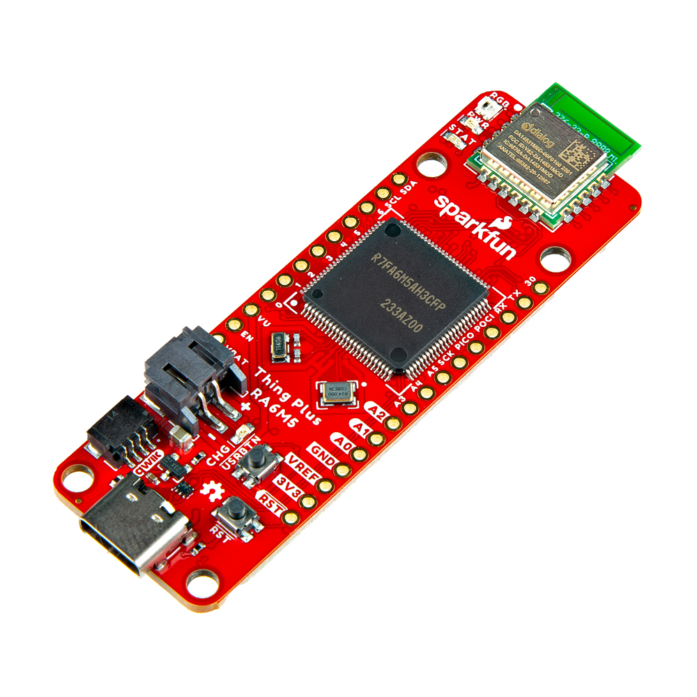
Clocking in at 200MHz, the RA6M5 is a high-performance microcontroller from Renesas that is perfect for real-time applications. The SparkFun Thing Plus - RA6M5, is our latest Thing Plus board featuring the standard Qwiic connector, JST LiPo battery connector, 21 GPIO pins broken out in a Feather footprint, and status indicator LEDs. At the core is the RA6M5 microcontroller, a low-power Arm® Cortex®-M33 processor with an available 512kB of SRAM and 2MB of Flash and an extensive list of peripheral capabilities. Additionally, we have included 16MB of QSPI Flash and an SD card slot on the board, so users won't have to worry about running out of memory space or data storage options.
The SparkFun RA6M5 Thing Plus also features Bluetooth® Low Energy connectivity, thanks to the provided DA14531MOD module (also from Renesas). When actively transmitting, the DA14531MOD sips a mere 4mA and is capable of operating from a small coin-cell battery. The firmware provided on the module features Renesas' SmartBond™ - CodeLess™ AT command set. Therefore, users only need to send AT commands to configure a Bluetooth connection; without the need to reprogram the module.
Note
While the Thing Plus - RA6M5 does include some 5V tolerant pins, it is primarily a 3.3V logic-level board.
While the full capabilities of the RA6M5 support a broad range of features, only a limited set may be implemented, by default, in the Renesas-Arduino core. However, the capabilities of the Thing Plus - RA6M5 should be comparable to the Arduino Portenta C33; with the exclusion of WiFi connectivity.
Required Materials
To get started, users will need a few items. Some users may already have a few of these items, feel free to adjust accordingly.
- Computer with an operating system (OS) that is compatible with all the software installation requirements
- USB 3.1 Cable A to C - 3 Foot - Used to interface with the RA6M5 Thing Plus (1)
- SparkFun RA6M5 Thing Plus
- If your computer doesn't have a USB-A slot, then choose an appropriate cable or adapter.
Data Logging
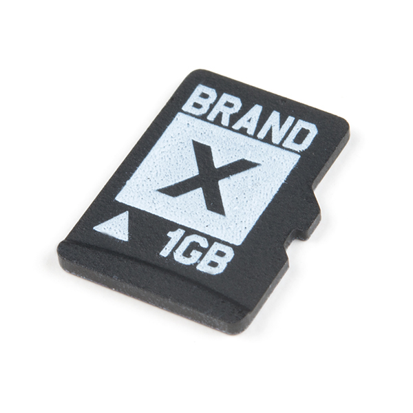
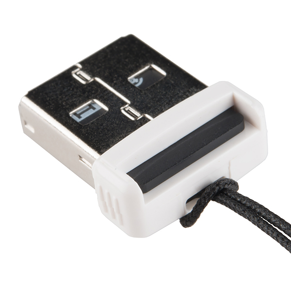
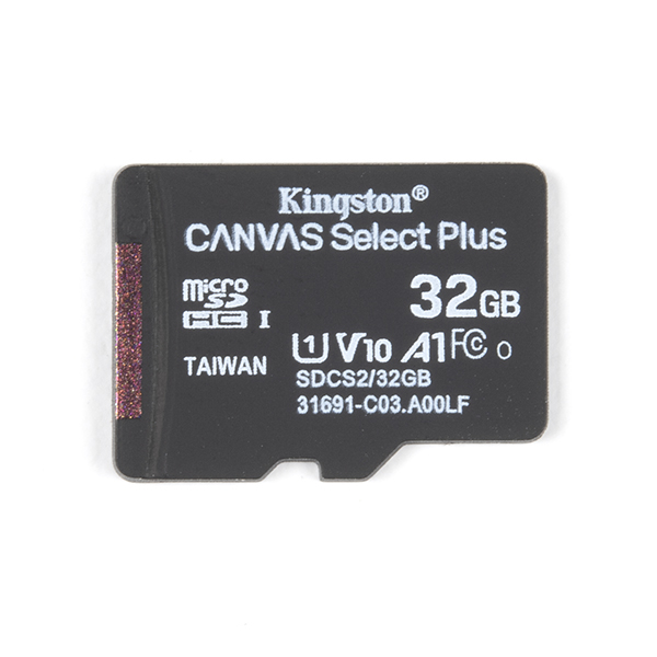
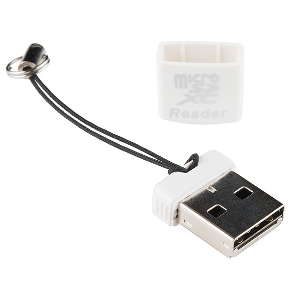
This board is capable of logging data to an µSD card. Please check out the memory cards and accessories in our product catalog.
Headers and Wiring
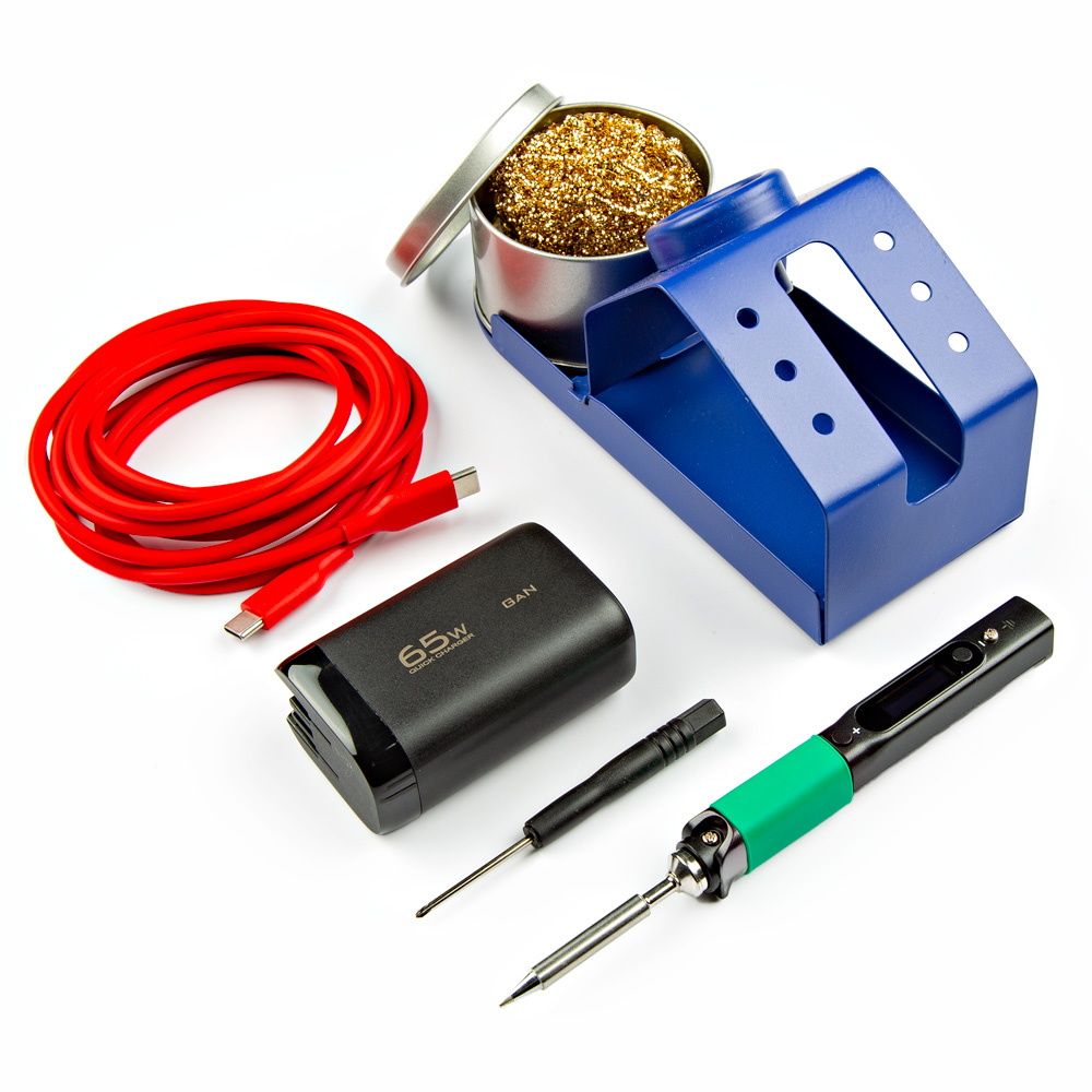
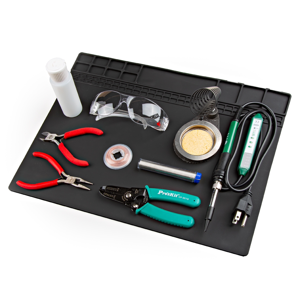
To add headers or hookup wires, users will need soldering equipment and headers/wires.
New to soldering?
Check out our How to Solder: Through-Hole Soldering tutorial for a quick introduction!
Li-Po Battery
For mobile applications, users will want to pick up a single-cell LiPo battery from our catalog.
Qwiic Devices and Cables
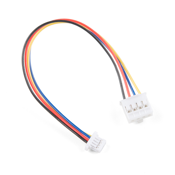
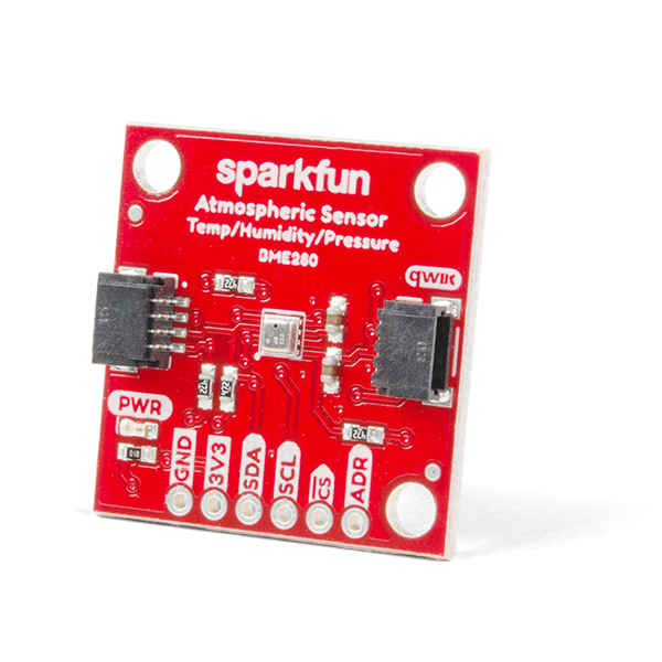
Our Qwiic connect system is a simple solution for daisy chaining I2C devices without the hassle of soldering or checking wire connections. Check out other Qwiic devices from our catalog.
-
SparkFun Qwiic Cable Kit
KIT-15081 -
Qwiic Cable - Grove Adapter (100mm)
PRT-15109 -
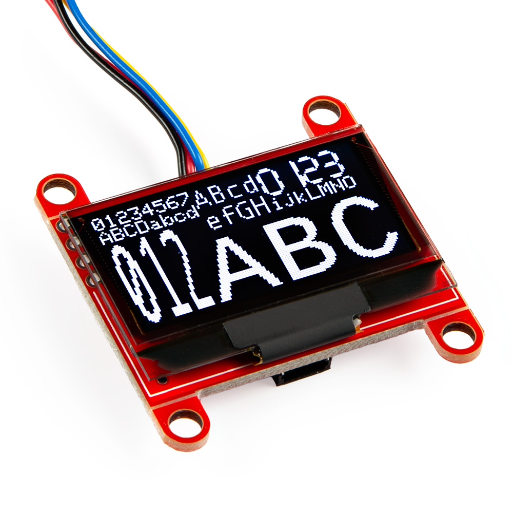
SparkFun Qwiic OLED - (1.3in., 128x64)
LCD-23453 -
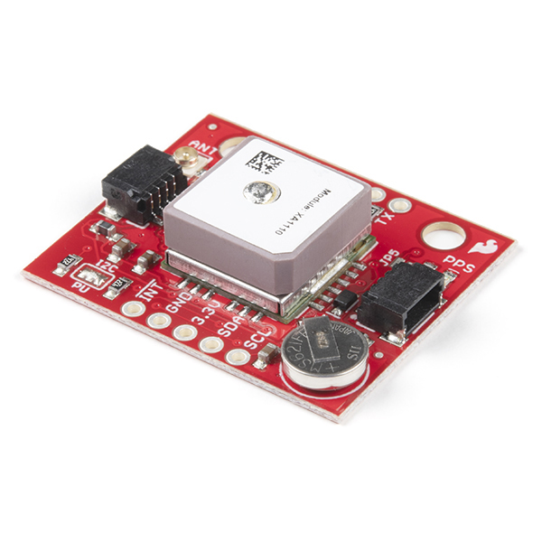
SparkFun GPS Breakout - XA1110 (Qwiic)
GPS-14414 -
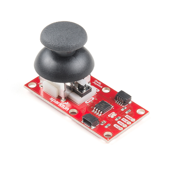
SparkFun Qwiic Joystick
COM-15168 -
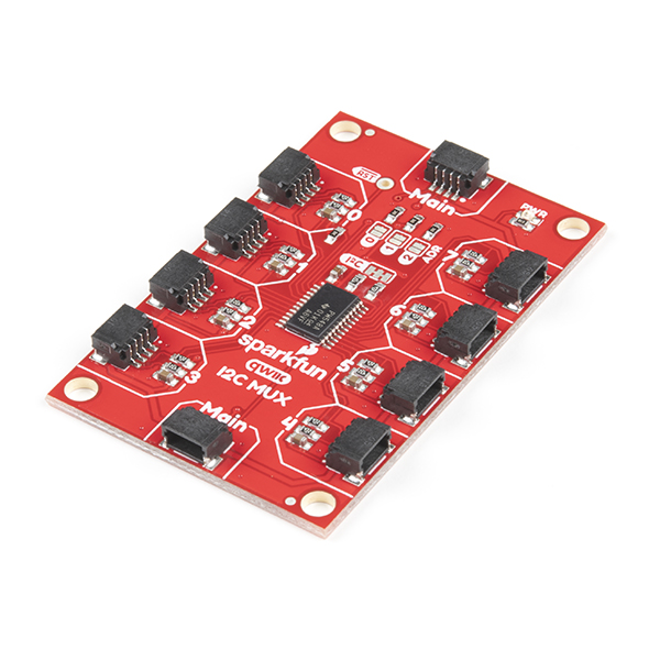
SparkFun Qwiic Mux Breakout - 8 Channel (TCA9548A)
BOB-16784 -
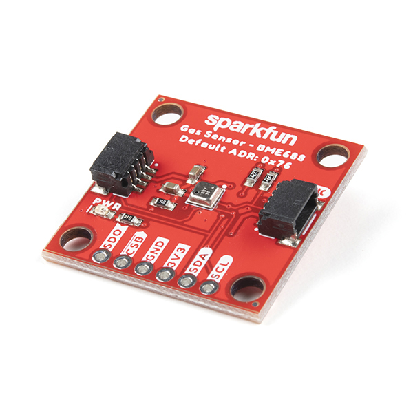
SparkFun Environmental Sensor - BME688 (Qwiic)
SEN-19096 -
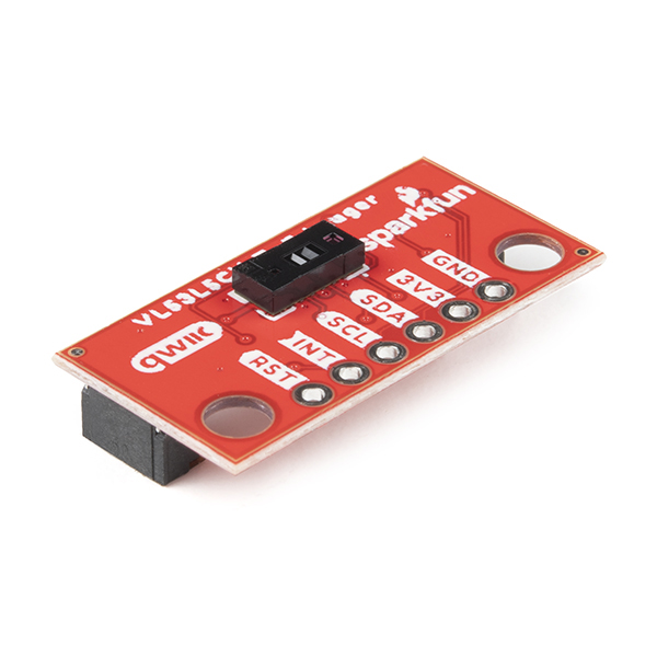
SparkFun Qwiic Mini ToF Imager - VL53L5CX
SEN-19013
What is Qwiic?


The Qwiic connect system is a solderless, polarized connection system that allows users to seamlessly daisy chain I2C boards together. Play the video, to learn more about the Qwiic connect system or click on the banner above to learn more about Qwiic products.

Features of the Qwiic System


Qwiic cables (4-pin JST) plug easily from development boards to sensors, shields, accessory boards and more, making easy work of setting up a new prototype.


There's no need to worry about accidentally swapping the SDA and SCL wires on your breadboard. The Qwiic connector is polarized so you know you’ll have it wired correctly every time.
The part numbers for the PCB connector is SM04B-SRSS (Datasheet) and the mating connector on the cables is SHR04V-S-B; or an equivalent 1mm pitch, 4-pin JST connection.


It’s time to leverage the power of the I2C bus! Most Qwiic boards will have two or more connectors on them, allowing multiple devices to be connected.
Jumper Modification
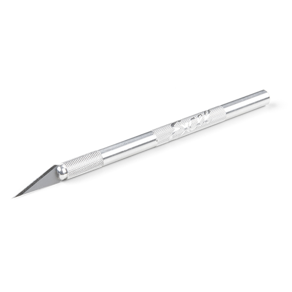
To modify the jumpers, users will need soldering equipment and/or a hobby knife.
New to jumper pads?
Check out our Jumper Pads and PCB Traces Tutorial for a quick introduction!
Suggested Reading
As a more sophisticated product, we will skip over the more fundamental tutorials (i.e. Ohm's Law and What is Electricity?). However, below are a few tutorials that may help users familiarize themselves with various aspects of the board.
-
Installing the Arduino IDE
-
Installing an Arduino Library
-
Installing Board Definitions in the Arduino IDE
-
Logic Levels
-
Analog vs. Digital
-
Analog to Digital Conversion
-
Pulse Width Modulation
-
Serial Communication
-
Serial Terminal Basics
-
Data Types in Arduino
-
I2C
-
SPI
-
Processor Interrupts with Arduino
-
How to Solder: Through-Hole Soldering
-
How to Work with Jumper Pads and PCB Traces
-
Integrated Circuits
Hardware Overview
Dimensions
The circuit board dimensions are illustrated in the drawing below; the measurements are in inches.
Dimensions (PDF) of the RA6M5 Thing Plus, in inches.
Need more measurements?
For more information about the board's dimensions, users can download the Eagle files for the board. These files can be opened in Eagle and additional measurements can be made with the dimensions tool.
Eagle - Free Download!
Eagle is a CAD program for electronics that is free to use for hobbyists and students. However, it does require an account registration to utilize the software.
 Dimensions Tool
This video from Autodesk demonstrates how to utilize the dimensions tool in Eagle, to include additional measurements:

USB Connector
The USB-C connector is used to provide power and program the board. For most users, it will also be the primary programming interface for the RA6M5 Thing Plus.
USB-C connector on the RA6M5 Thing Plus.
Power
The RA6M5 Thing Plus only requires 3.3V to power the board. However, the simplest method to power the board is through the USB-C connector. Alternatively, the 3V3, VBAT, and VUSB pins can also be used to supply power to the board.
flowchart LR
    A[USB-C] === B(("`**VUSB**`")) ===> |VUSB > VBAT| Switch;

    subgraph Battery Charger
        direction LR
        C[MCP73831] -.-> D[LiPo Battery];
    end

    subgraph Switch
        F[LM66200];
    end

    B ==> C;
    D === E(("`**VBAT**`")) == VBAT > VUSB ==> Switch;

    F ===   H[RT9080] ==> I(("`**3V3**`"));
    F === G[RT9080] ==> J(("`**VREF**`"));

    click B "#vusb"
    click C "#charging-circuit"
    click E "#vbat"
    click F "#power-control"
    click J "#vref"
    click I "#3v3"
Below, is a summary of the power circuitry for this board:
- Primary power for the RA6M5 Thing Plus
- Powers the RA6M5 module, DA14531MOD, QSPI flash, µSD card slot, Qwiic connector, WS2812 RGB LED, and power LED
- A regulated 3.3V is provided by an RT9080 LDO from
VUSBorVBAT- The output voltage from the RT9080 is controlled by the
ENpin on the board - The RT9080 can source up to 600mA of current, which is only limited by the power source from the LM66200 switch
- The power source from the LM66200 is automatically switched between
VUSBorVBAT, based on which has the greater voltage
- The power source from the LM66200 is automatically switched between
- The output voltage from the RT9080 is controlled by the
- As an input, it requires a regulated 3.3V to avoid contention with the LDO regulator
The input voltage range for the RT9080 is 1.2-5.5V
- Usually powered through the USB-C connector (5V)
- Input voltage range: 3.75 - 5V
- The maximum voltage is limited by the ideal diode switch at 5.5V (1.6-5.5V)
- The minimum voltage is limited by the charge controller at 3.75V (3.75-6V)
- Primary power source for the RT9080 LDOs when
VUSB>VBAT; via the LM66200 ideal diode switch - Powers the MCP73831 linear charge management controller
- Provides a 213mA (max) rate of charge to a connected battery
- The voltage from the JST battery connector; is meant for single-cell LiPo batteries
- A connected battery will be charged by the MCP73831 charge controller, when sufficient power is provided from
VUSB
- A connected battery will be charged by the MCP73831 charge controller, when sufficient power is provided from
- Primary power source for the RT9080 LDOs when
VBAT>VUSB; via the LM66200 ideal diode switch - A battery's charge can be monitored through the MAX17048 fuel gauge
- The analog reference voltage for the RA6M5 module's ADC and DAC channels
- Provided by a RT9080 LDO regulator, separate from one providing the
3V3power supply
- Provided by a RT9080 LDO regulator, separate from one providing the
The input voltage range for the RT9080 is 1.2-5.5V
- The common ground or the 0V reference for the voltage supplies
- The 4-pin JST connector provides a regulated 3.3V voltage to peripheral Qwiic devices from
3V3
Detailed Diagram
flowchart LR
    D === E(("`**VBAT**`")) == VBAT > VUSB ==> Switch;
    A[USB-C] === B(("`**VUSB**`")) == VUSB > VBAT ==> Switch;
    C --- T[CHG LED];

subgraph Battery Charger
        C[MCP73831] -.-> D[LiPo<br>3.5-4.2V]
    end

    subgraph Switch
        S[LM66200];
        S === I[RT9080] & H[RT9080];
    end

    subgraph Powered_Components
        L[PWR LED];
        M[RA6M5] --- N[DA14531MOD];
        M --- O[QSPI Flash];
        M --- P[SD Card];
        M --- Q[WS2812 LED];
        M --- I2C;
        subgraph I2C
            R[Qwiic Connector];
            F[MAX17048];
        end
    end

    B ==> C;
    B ====> T;
    I --- U(("`**EN**`"));
    I ==> K(("`**3V3**`")) === Powered_Components;
    H ==> J(("`**VREF**`")) --> M;
    H --- W(("`**D37**`")) --- M;
    D ------ F;
    Switch --- V(("`**D38**`")) --- M;
For more details, users can reference the schematic and the datasheets of the individual components in the power circuitry.
Power Status LED
The red, PWR LED will light up once 3.3V is supplied to the board; however, for most users, it will light up when 5V is supplied through the USB connection or when a LiPo battery is connected to the JST connector.
The PWR status LED indicator on the RA6M5 Thing Plus.
Charging Circuit
The charging circuit utilizes the MCP73831 linear charge management controller from Microchip Technologies, which is powered by the USB-C connector or VUSB. The controller provides a 213mA charge rate for a LiPo battery connected to the JST connector. Active charging is indicated by the yellow, CHG LED. If the charge controller is shut down or charging is complete, the CHG LED will turn off. The board also includes a MAX17048 fuel gauge from Analog Devices to monitor the charge left on the battery.
flowchart LR
    A[USB-C] === B(("`**VUSB**`")) ==> C & G;
    D ===> E(("`**VBAT**`"));
    D --- F[MAX17048] === H(("`**3V3**`"));
    G[CHG LED] --- C[MCP73831];

    subgraph Battery Charger
        C -.-> |213mA| D[LiPo<br>3.5-4.2V];
    end
The CHG status LED and JST connector for the battery on the RA6M5 Thing Plus.
For more details, please refer to the MCP73831 and MAX17048 datasheets, schematic, and the Status LEDs and Battery Fuel Gauge sections below.
Power Control
The primary power source for the RT9080 LDO regulators is automatically switched between VUSB and VBAT by the LM66200 ideal diode switch; based on their voltage levels. This will be indicated by the ST pin of the LM66200, which is connected to the P001 GPIO (D38) of the RA6M5. A LOW state will indicate that power is being supplied from VUSB (or the USB-C connector); while a HIGH state will indicate power is being drawn from VBAT (or the battery JST connector).
flowchart LR
    A[USB-C] === B(("`**VUSB**`")) == VUSB > VBAT ==> Switch;
    U(("`**D38**`")) --- Switch;
    D[LiPo] === E(("`**VBAT**`")) == VBAT > VUSB ==> Switch;

    subgraph Switch
        S[LM66200];
    end

    S === H[RT9080] ===> J(("`**3V3**`"));
    H --- T(("`**EN**`"));
    I --- V(("`**D37**`"));
    S === I[RT9080] ===> K(("`**VREF**`"));
The 3.3V regulated output from the primary RT9080 is enabled by default and controlled by the EN pin on the board. Meanwhile, the voltage output from the RT9080 for the analog reference voltage (VREF) of the RA6M5 is controlled by its P500 GPIO (D37). Users can disable the 3.3V power output of either of the RT9080 LDO regulators, by setting the associated control pin LOW.
The power inputs/outputs and EN pin on the RA6M5 Thing Plus.
For more details, please refer to the LM66200 datasheet, RT9080 datasheet, and schematic.
RA6M5 Microcontroller
The brains of the board is the RA6M5 microcontroller from Renesas, a low-power Arm® Cortex®-M33 processor with a clock speed up to 200Mhz, 512kB of SRAM, and 2MB of flash memory. This high-performance microcontroller features an extensive list of peripheral capabilities and is perfect for real-time applications.
- Arm® Cortex®-M33 Core
- Clock Frequency: 200MHz
- Flash Memory: 2MB (code); 8kB (data)
- SRAM: 512kB w/ ECC Support
- Arm Memory Protection Unit (Arm MPU)
- Secure Crypto Engine
- Two Watchdog Timers (WDT)
- Operating Voltage: 3.0V to 3.6V
- Current Consumption:
- Maximum: 143mA
- Normal: 32mA
- Sleep: 11mA
- Deep Sleep: 0.9-131µA
- Current Consumption:
- Operating modes:
- Single-chip or SCI/USB boot
- Operating Temperature: -40 to 85 °C
- 75 GPIO Pins
- RTC with Calendar
- CRC Calculator
- Internal Temperature Sensor
Peripherals
- 12-bit ADC (x6)
- 12-bit DAC (x2)
- 32-bit PWM Channels (x4)
- 16-bit PWM Channels (x6)
- UART (x10)
- I2C Bus (x3)
- SPI Bus (x2)
- QSPI (x1)
- SD/MMC Host Interface
- OSPI (x1)
- CAN Interface
- USB 2.0 (Full/High Speed)
- Ethernet MAC/DMA Controller
- Serial Sound Interface Enhanced
- Consumer Electronics Control
- Capacitive Touch Sensing
Note
Users should be aware that not all of the features, listed above, will be available in the Arduino IDE.
DFU Mode
If users are having issues uploading code to the board, the RA6M5 can be manually forced into DFU mode. This issue, often occurs when the USB connection is busy and a reset can't be triggered on the RA6M5, to initialize the upload process. To force the RA6M5 Thing Plus into DFU mode:
- Double-tap the RST button
- The
STATLED should be fading in/out very slowly
- The
- Users should now, be able to upload a new program
- It shouldn't be necessary to select a COM port in the Arduino IDE; only the board needs to be selected
- Once programming is complete, the MCU should reboot on its own. Otherwise:
- Press the RST button
- Power cycle the board
For more technical specifications for the RA6M5 microcontroller, please refer to the RA6M5 datasheet and RA6M5 user manual.
Debugging Pins
Debug pins are available for the RA6M5, as 0.1" test points on the board. However, the debugging feature is only available through the Renesas FSP (not covered in this tutorial).
| GND | SWCLK | 3.3V | | |
| RST | SWO | SWDIO |
| GND | TCK | 3.3V | | |
| RST | TDO | TMS |
Pin Connections
In case users are interested, these are the pin connections of the debugging test points for the RA6M5. For more details, please reference the schematic and Eagle files.
TMS/SWDIO:P108TCK/SWCLK:P300TDO/SWO:P109TDI:P110(POCI/D17)
Note
In order to debug the RA6M5, users will need a debug probe. We recommend the J-Link debug probes from Segger. However, users should verify the supported devices before purchasing these products; for example, we had a few issues with the J-Link EDU Mini.
For more details, please refer to the schematic and RA6M5 datasheet.
Pin Functions
While there are 75 GPIO pins that are available on the RA6M5, only 44 GPIO pins are utilized with the RA6M5 Thing Plus. Additionally, of those 44 GPIO, only 21 GPIO pins are broken out into the PTH breakout pins. The breakout pins are in a Feather form-factor layout with a 0.1" pitch spacing to make them compatible with standard headers and Feather shields/wings.
Some of the RA6M5's peripheral capabilities may be inaccessible to users with the available 44 GPIO. However, any of the available GPIO pins can operate as digital I/O; with several of these pins featuring additional peripheral support. The pins utilized by the RA6M5 Thing Plus, along with their capabilities, are summarized in our graphical datasheet and detailed in the sections below.

Board Limitations
Users should be aware that some of the features of the RA6M5 may not be available in the Arduino IDE. This is due to either the lack of support in the Renesas-Arduino core and/or pins that are unavailable on the RA6M5 Thing Plus. For the full capabilities of the RA6M5, the Renesas FSP should be utilized.
- Only one I2C bus is defined.
- Only three UART interfaces are defined.
Serial- UART (USB)Serial1-RX/TXGPIO PinsSerial2- DA14531MOD UART
- Only one SPI bus is defined.
Note
- All the GPIO on the RA6M5 Thing Plus are
3.3V pins
- While the datasheet specifies there are fourteen 5V-tolerant I/O pins; most of the exposed pins are not 5V-tolerant! To interface with higher voltage components, a logic-level adapter should be utilized.
Any GPIO pin on the RA6M5 Thing Plus can operate as a digital I/O (input or output). To access this functionality in the Arduino IDE, users must first declare the pin operation in their setup() loop, using the pinMode(pin, mode) function.
- Input
-
If a pin is configured as an
INPUT, the microcontroller can monitor if the pin's state is HIGH or LOW. As Input pins are High Impedance, it takes very little current to move the input pin from one state to another.Arduino
In the Arduino IDE, this is accessed through the
digitalRead(pin)function, which returns aHIGHorLOWvalue. - Output
-
If a pin is configured as an
OUTPUT, the microcontroller can provide a HIGH or LOW voltage output from the pin. As Output pins are Low Impedance, they can provide a certain amount of current for other circuits.Arduino
In the Arduino IDE, this is accessed through the
digitalWrite(pin, value)function and providing aHIGHorLOWvalue.Warning
There are electrical limitations to the amount of current that I/O pins can sink or source. For more details, check out the RA6M5 datasheet.
Tip - Creating a PWM Output
A digital output pin can only either be fully on HIGH or fully off LOW. By turning a digital pin's output, on and off very quickly with precise timings, the average voltage can be controlled and emulate an analog output. This method is called PWM.
Please refer to the PWM Outputs tab for more instructions or check out this great tutorial to learn more about pulse width modulation.
The RA6M5 supports up to four 32-bit and six 16-bit PWM (Pulse Width Modulation) channels on most of its GPIO pins. A PWM output will produce a square waveform with a variable duty cycle, a ratio of time a signal is HIGH for a given wave period. In the Arduino IDE, this feature is accessed using the analogWrite(pin, value) function, where the desired duty cycle is specified as an 8-bit value.
Mean Value ≠ Analog
PWM signals are often mistaken for analog signals; however, a PWM output is not a true analog signal. These signals can emulate an analog output, based on the average voltage output of their square waveform for a specific duration of time.
Arduino
By default, in the Arduino IDE, analogWrite() accepts an 8-bit value. To change the resolution of the PWM signal for the analogWrite() function, use the analogWriteResolution(bits) function.
A PWM output is not a true analog signal. For a true analog output, please refer to the Analog Outputs tab.
Tip
To learn more about pulse width modulation (PWM), check out this great tutorial.
The RA6M5 has six 12-bit ADC channels on its GPIO pins to read analog signals. This functionality is accessed in the Arduino IDE using the analogRead(pin) function. The available ADC pins are highlighted in the image below.
Arduino
In the Arduino IDE, analogRead() returns a 10-bit value by default. To change the resolution of the value returned by the analogRead() function, use the analogReadResolution(bits) function.
Tip
To learn more about analog vs. digital signals, check out this great tutorial.
The RA6M5 has two 12-bit DAC channels on its GPIO pins to output analog signals. This feature is accessed in the Arduino IDE using the AnalogWave library from the Renesas Arduino core. The available DAC pins are highlighted in the image below.
Arduino
When implementing the AnalogWave library, users will need to link the library and create an instance of the analogWave class with a DAC pin declared for the output.
#include "analogWave.h" // Include the library for analog waveform generation

analogWave wave(pin);   // Create an instance of the analogWave class, using a DAC pin
For more information, please refer to the Analog I/O example in this guide.
Tip
To learn more about analog vs. digital signals, check out this great tutorial.
The RA6M5 supports up to ten UART ports. However, only the three UART ports are predefined in the Renesas Arduino core. In the Arduino IDE, the serial communication class is used for the USB connection (Serial), the labeled UART I/O pins on the board (Serial1), and UART connection to the DA14531MOD (Serial2).
Arduino
By default, in the Arduino IDE, the RA6M5 Thing Plus board definition supports:
| Arduino Object | GPIO Pins | Connection |
|---|---|---|
Serial |
USB | |
Serial1 |
RX - P408 (D21)TX - P409 (D20) |
PTH Pins |
Serial2 |
RX - P601 (D32)TX - P602 (D31)RTS - P301 (D33)CTS - P303 (D34) |
DA14531MOD Bluetooth Module |
To utilize serial communication on other pins, users will need to create a custom serial port object and declare which pins to access.
Shared UART Port
Users should be aware that the UART port for pins D17/D18, UART9, is also utilized for communication with the DA14531MOD Bluetooth module. Therefore, if UART9 is already being utilized for the DA14531MOD; the UART port will be unavailable on pins D17/D18.
| UART Port | Arduino Object | GPIO Pins | Connection |
|---|---|---|---|
| USB | Serial |
USB | |
| UART3 | Serial1 |
RX - P408 (D21)TX - P409 (D20) |
PTH Pins |
| UART9 | Serial2 |
RX - P601 (D32)TX - P602 (D31)RTS - P301 (D33)CTS - P303 (D34) |
DA14531MOD Bluetooth Module |
| UART9 | RX - P110 (D17)TX - P109 (D18) |
PTH Pins | |
| UART7 | RX - P402 (D05)TX - P401 (D15)RTS - P403 (D04)CTS - P404 (D03) |
PTH Pins |
The RA6M5 supports up to two SPI buses. However, only a single SPI port is defined in the Renesas Arduino core. In the Arduino IDE, the SPI communication class is configured to utilize pins SCK - P111/D19, POCI - P110/D17, PICO - P109/D18, and P112/D0 for its chip select.
New Nomenclature
To comply with the latest OSHW design practices, we have adopted the new SPI signal nomenclature (SDO/SDI and PICO/POCI). The terms Master and Slave are now referred to as Controller and Peripheral. The MOSI signal on a controller has been replaced with SDO or PICO. Please refer to this announcement on the decision to deprecate the MOSI/MISO terminology and transition to the SDO/SDI naming convention.
Arduino
By default, in the Arduino IDE, the RA6M5 Thing Plus board definition supports:
| SPI Pin | GPIO |
|---|---|
| POCI | P110 (D17) |
| PICO | P109 (D18) |
| SCK | P111 (D19) |
| CS | P112 (D0) |
To utilize SPI communication on other pins, users will need to create a custom SPI object and declare which pins to access.
Tip
To learn more about the serial peripheral interface (SPI) protocol, check out this great tutorial.
The RA6M5 supports up to three I2C buses. However, only a single I2C bus is defined in the Renesas Arduino core. In the Arduino IDE, the Wire class is configured to utilize the SDA - P401/D15 and SCL -P400/D16 pins. These pins also share the same I2C bus as the Qwiic connector and MAX17048 fuel gauge.
Arduino
By default, in the Arduino IDE, the RA6M5 Thing Plus board definition supports:
| I2C Pin | GPIO |
|---|---|
| SCL | P400 (D16) |
| SDA | P401 (D15) |
To utilize the I2C ports on other pins, users will need to create a custom Wire object and declare which pins to access.
Tip
To learn more about the inter-integrated circuit (I2C) protocol, check out this great tutorial.
What is Qwiic?


The Qwiic connect system is a solderless, polarized connection system that allows users to seamlessly daisy chain I2C boards together. Play the video, to learn more about the Qwiic connect system or click on the banner above to learn more about Qwiic products.

Features of the Qwiic System


Qwiic cables (4-pin JST) plug easily from development boards to sensors, shields, accessory boards and more, making easy work of setting up a new prototype.


There's no need to worry about accidentally swapping the SDA and SCL wires on your breadboard. The Qwiic connector is polarized so you know you’ll have it wired correctly every time.
The part numbers for the PCB connector is SM04B-SRSS (Datasheet) and the mating connector on the cables is SHR04V-S-B; or an equivalent 1mm pitch, 4-pin JST connection.


It’s time to leverage the power of the I2C bus! Most Qwiic boards will have two or more connectors on them, allowing multiple devices to be connected.
The RA6M5 provides IRQ support on several of its pins. In the Arduino IDE, interrupt requests are configured using the attachInterrupt(digitalPinToInterrupt(pin), ISR, mode) function. The available IRQ pins are highlighted in the image below.
Arduino
In the Arduino IDE, interrupt requests are configured using the attachInterrupt(digitalPinToInterrupt(pin), ISR, mode) function, where:
pin- The GPIO pinISR- The interrupt service routine to call/execute when the interrupt occursmode- Defines how the interrupt should be triggered:LOW- When the pin is LOWCHANGE- Whenever the pin changes valueRISING- When the pin changes from LOW to HIGHFALLING- When the pin changes from HIGH to LOW
Tip
To learn more about interrupts, check out this great tutorial.
For more technical specifications on the I/O pins, please refer to the schematic, RA6M5 datasheet, and RA6M5 user manual.
DA14531MOD BLE Module
The DA14531MOD, from Renesas, provides the RA6M5 Thing Plus with Bluetooth connectivity. When actively transmitting, the DA14531MOD sips a mere 4mA; low enough to operate on a small coin-cell battery. The module is programmed with a precompiled binary of the CodeLess SDK, featuring Renesas' SmartBond™ - CodeLess™ AT command set. With the implementation of an AT command platform to configure the DA1431MOD's Bluetooth connectivity, source code is no longer required to be written for the module, to operate as a peripheral device.
- Bluetooth 5.1 system-on-chip (SoC)
- Supports up to three connections
- 32-bit Arm® Cortex® M0+
- Clock frequency: 16 MHz
- Memory:
- Flash: 128 Kb
- RAM: 48 Kb
- ROM: 144 Kb
- OTP: 32 Kb
- Operating range (1.8 V - 3.6 V)
- Receive: 2mA
- Transmit: 4mA
- Sleep: 1.8 µA
- Radio
- Transmit Power: -19 to +2.2 dBm
- Receiver Sensitivity: -93 dBm
Debug Pins
The SWD pins for the DA14531MOD are available as 0.1" test points on the board. However, users are unlikely to utilize these pins unless they wish to modify the pre-existing firmware on the DA14531MOD.
| GND | SWCLK | 3.3V | | |
| RST | SWDIO |
Info
In case users are interested, these are the pin connections of the SWD test points to the DA14531MOD. For more details, please reference the schematic.
SWDIO:P0_10SWCLK:P0_2
Note
In order to debug the DA14531MOD, users will need a debug probe. We recommend the J-Link debug probes from Segger. However, users should verify the supported devices before purchasing these products; for example, we had a few issues with the J-Link EDU Mini.
CodeLess Firmware
The CodeLess™ AT command allows users to easily configure the RA6M5 Thing Plus as a central or peripheral Bluetooth device. In addition, users can also potentially implement OTA updates with the CodeLess™ AT commands.
The precompiled binary from the CodeLess SDK utilized as the firmware image, on the DA14531MOD of the RA6M5 Thing Plus, is the codeless_531_datapump.hex (CodeLess for DA1453x datapump).
Serial Port Setting
The default settings of the serial port on the DA14531MOD, for AT commands:
- BaudRate : 57600
- DataBits : 8
- StopBits : 1
- Parity : None
- Flow Control : None
- Transmit Text: Append CR
For more details, please refer to the DA14531 datasheet, and CodeLess user manual.
External Memory
QSPI Flash
The RA6M5 Thing Plus features 16MB of QSPI Flash memory, with the MX25L12833F from Macronix. The MX25L12833F QSPI Flash memory provides users with high-speed non-volatile memory to develop and execute data-driven applications. This feature is perfect for data logging, data processing, or executing memory-intensive algorithms. The QSPI Flash memory can also be used to store a firmware backup or enable software updates.
The Flash memory is connected to the following GPIO:
- CLK: GPIO
P100(D40) - D0: GPIO
P102(D42) - D1: GPIO
P101(D43) - D2: GPIO
P104(D44) - D3: GPIO
P103(D45) - SS: GPIO
P501(D41)
For more details, please refer to the MX25L12833F datasheet, the schematic, RA6M5 datasheet, and RA6M5 user manual.
µSD Card Socket
The µSD card socket is connected to the SD host interface for fast data logging. This feature is useful for data collection over extended periods and for simplifying data retrieval.
The µSD card slot is connected to the following GPIO:
- CLK: GPIO
P214(D22) - D0: GPIO
P208(D24) - D1: GPIO
P410(D25) - D2: GPIO
P206(D26) - D3: GPIO
P205(D27)
Data Corruption
To avoid corrupting an SD card, users should disable all activity with the SD card before removing it from the RA6M5 Thing Plus.
The FATFileSystem library built into the Renesas-Arduino core, supports µSD cards with a FAT32 file system (i.e. SD cards up to 32GB in size).
- While users may be able to use cards with a higher storage capacity, we highly advise against it. As users may experience data loss due to a corrupt file system (i.e. SD cards with a storage capacity greater than 32GB are not meant to be formatted with a FAT32 file system).
Note
The RA6M5 Thing Plus, offers users additional control of the SD card slot with the following pin connections:
| Pin Name | Connection to RA6M5 | Operation | Function |
|---|---|---|---|
| SDEN | GPIO P708 (D35) |
Active LOW | Controls power to the SD card slot. - A LOW signal will disable power to the SD card slot |
| CD | GPIO P210 (D28) |
Active LOW | Read the pin latch, to determine if an SD card is inserted - A LOW signal will indicate an SD card is present |
| WP | GPIO P414 (D29) |
Active LOW | Read if the write protection is engaged on the SD card - A LOW signal will indicate write protection is enabled on the SD card |
For more details, please refer to the schematic, RA6M5 datasheet, and RA6M5 user manual.
I2C Bus
Qwiic Connector
A Qwiic connector is provided for users to seamlessly integrate with SparkFun's Qwiic Ecosystem. Otherwise, users can also access the I2C bus through the PTH pins broken out on the board.
Qwiic connector and I2C pins on the RA6M5 Thing Plus.
What is Qwiic?


The Qwiic connect system is a solderless, polarized connection system that allows users to seamlessly daisy chain I2C boards together. Play the video, to learn more about the Qwiic connect system or click on the banner above to learn more about Qwiic products.

Features of the Qwiic System


Qwiic cables (4-pin JST) plug easily from development boards to sensors, shields, accessory boards and more, making easy work of setting up a new prototype.


There's no need to worry about accidentally swapping the SDA and SCL wires on your breadboard. The Qwiic connector is polarized so you know you’ll have it wired correctly every time.
The part numbers for the PCB connector is SM04B-SRSS (Datasheet) and the mating connector on the cables is SHR04V-S-B; or an equivalent 1mm pitch, 4-pin JST connection.


It’s time to leverage the power of the I2C bus! Most Qwiic boards will have two or more connectors on them, allowing multiple devices to be connected.
Battery Fuel Gauge
The MAX17048 fuel gauge, from Analog Devices, measures the approximate charge/discharge rate, state of charge (SOC) (based on ModelGauge algorithm), and voltage of a connected battery. The sensor is also powered directly from a connected LiPo battery (VBAT).
| I2C Address | 0x36 (7-bit) 0x6C (write)/0x6D (read) |
|---|---|
| Voltage Measurement | Range: 2.5 - 5 V Precision: ±7.5 mV/Cell Resolution 1.25 mV/Cell |
| Current Consumption | Sleep: .5 - 2 µA Hibernate: 3 - 5 µA Active: 23 - 40 µA |
Alert Pin
The fuel gauge features an Alert pin, which can be configured to trigger an interrupt (active LOW) on GPIO P000 (D39) of the RA6M5 for:
- Low Charge
- 1% Charge (Remaining)
- IC Reset
- Overvoltage
- Undervoltage
For more information, please refer to the MAX17048 datasheet and the schematic.
Status LEDs
There are four status LEDs on the RA6M5 Thing Plus:
PWR- Power (Red)- Illuminates once power is applied to
3V3
- Illuminates once power is applied to
RGB- WS2812 (RGB)- An addressable WS2812 LED
- Connected to GPIO
P105(D13orRGB_LED) of the RA6M5
STAT- Status (Blue)- Connected to the RA6M5
P106(D14/LED_BUILTIN) GPIO
- Connected to the RA6M5
CHG- Battery Charge (Yellow)- ON - Actively charging a battery
- OFF - The charge controller is shut down or battery charging is complete
Buttons
There are two buttons on the RA6M5 Thing Plus: RST and USRBTN
Buttons on the RA6M5 Thing Plus.
- USRBTN - The user button is provided as an available input for the RA6M5; it is connected to GPIO
P415(D31) - RST - The reset button allows users to reset the firmware running on the RA6M5 without interrupting the power
DFU Mode
If users are having issues uploading code to the board, the RA6M5 can be manually forced into DFU mode. This issue, often occurs when the USB connection is busy and a reset can't be triggered on the RA6M5, to initialize the upload process. To force the RA6M5 Thing Plus into DFU mode:
- Double-tap the RST button
- The
STATLED should be fading in/out very slowly
- The
- Users should now, be able to upload a new program
- It shouldn't be necessary to select a COM port in the Arduino IDE; only the board needs to be selected
- Once programming is complete, the MCU should reboot on its own. Otherwise:
- Press the RST button
- Power cycle the board
For more details, please refer to the schematic.
Jumpers
Never modified a jumper before?
Check out our Jumper Pads and PCB Traces tutorial for a quick introduction!
The five jumpers on the back of the board can be used to easily modify the hardware connections on the board.
PWR- Cut this jumper to disable the red,PWRLEDRST- Cut this jumper to disconnect the reset pin of the DA14531MOD from the RA6M5P115/D37GPIOSHLD- Cut this jumper to isolate the USB-C connector shield from GNDI2C- Open this dual-jumper to disconnect the pull-up resistors from theSDAandSCLCHG- Cut this jumper to disable the yellow,CHGLED
For more details, please refer to the schematic.
Hardware Assembly
USB Connector
The USB connection is utilized for programming and serial communication. Users only need to plug their RA6M5 Thing Plus into a computer using a USB-C cable.
The RA6M5 Thing Plus with USB-C cable attached.
LiPo Battery
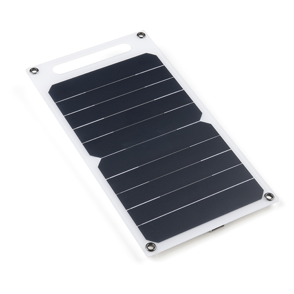
For remote IoT applications, a LiPo battery can be connected. Additionally, users may be interested in utilizing a solar panel and USB-C cable to recharge their battery.
Warning
Users should avoid pulling on the wires of a battery to disconnect it from the board. Instead, it is recommended that a pair of dikes (i.e. diagonal wire cutters), pliers, or tweezers be used to pull on the JST connector housing, to avoid damaging the battery wiring.
Breakout Pins
The PTH pins on the RA6M5 Thing Plus are broken out into 0.1"-spaced pins on the edges of the board.
New to soldering?
If you have never soldered before or need a quick refresher, check out our How to Solder: Through-Hole Soldering guide.
Headers
Headers are versatile in their compatibility with shields, breadboards, or jumper wires.
Soldering headers to the RA6M5 Thing Plus.
Stackable Headers
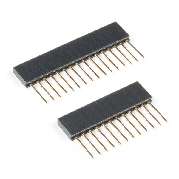
Our Feather Stackable Header Kit is a great option for stacking on shields (w/ Feather footprint) or on a breadboard; while leaving its pins still accessible.
SD Card Slot
The RA6M5 Thing Plus includes a µSD card slot on the back of the board. The cardholder functions through a push/pull operation. (The card slot doesn't include a spring retention mechanism; cards are held in place through friction.)
Users can slide-in or pull-out a µSD card from the cardholder.
SD Card Compatibility
The R6M5 Thing Plus supports µSD cards with a FAT32 file system (i.e. only cards up to 32GB in size).
Qwiic Devices
The Qwiic system allows users to effortlessly prototype with a Qwiic compatible I2C device without soldering. Users can attach any Qwiic compatible sensor or board, with just a Qwiic cable. (*The example below, is for demonstration purposes and is not pertinent to the board functionality or this tutorial.)
The BME688 environmental and VL53L1X distance Qwiic sensor boards connected to the RA6M5 Thing Plus.
Software Overview - Arduino IDE
Tip
For first-time users, who have never programmed before and are looking to use the Arduino IDE, we recommend beginning with the SparkFun Inventor's Kit (SIK), which is designed to help users get started programming with the Arduino IDE.
Most users should already be familiar with the Arduino IDE and its use. However, for those of you who have never heard the name Arduino before, feel free to check out the Arduino website. To get started with using the Arduino IDE, check out our tutorials below:
Arduino Core
Installation
Installing the Ported Renesas-Arduino Core
In order to program the RA6M5 Thing Plus in the Arduino IDE, users will need to install the Arduino Renesas Portenta board definitions from the Renesas-Arduino core. However, until the RA6M5 Thing Plus is officially adopted into the Renesas-Arduino core, users need to utilize our port of the Renesas-Arduino core.
- Before users can install our ported version of the Renesas-Arduino core, they should first install the Arduino Renesas Portenta board definitions of the official Renesas-Arduino core in the Arduino IDE.
- This will ensure that any required compilation and upload tools are installed for the Arduino core.
- In the Board Manager of the Arduino IDE, select and install the Arduino Renesas Portenta board definitions from the Renesas-Arduino core.

Installing the Renesas-Arduino core in the Arduino IDE.
-
Once installed, users will need to locate the
packagesdirectory for the Arduino cores in the Arduino IDE:-
Windows
On Windows, the directory location may vary based on whether the Arduino IDE was installed for an individual user or all users:
-
The user's
AppDatadirectory (hidden folder - primary):C:\Users\<insert username>\AppData\Local\Arduino15\packages -
The user's
ArduinoDatadirectory (local):C:\Users\<insert username>\Documents\Arduino\hardware -
The
Program FilesorProgram Files(x86)directories:C:\Program Files(x86)\Arduino IDE
-
-
MacOS
With Mac OS, users should check the
ApplicationsandLibrarydirectories:-
Librarydirectory (primary):~/Library/Arduino15/packages/ -
Applicationsdirectory (local):/Applications/Arduino.app/hardware
-
-
Linux
For Linux, this may be located in the following directories:
-
Primary:
/home/$USER/.arduino15/packages -
Local:
/home/$USER/Arduino/hardware
Tip
As mentioned in Arduino's guide for installing the Arduino IDE on Linux, users may need to run the following commands in the terminal:
In order to utilize the serial terminal or recognize the board in DFU mode, users may also need to run the following commands in the terminal:
$USERNAMEis the login username- After, a restart or logout is required
-
-
-
After the
packagesdirectory has been located, users will need to navigate to the Renesas Arduino core. It is usually located in the./arduino/hardware/renesas_portenta/<version number>/directory of thepackagesfolder. - The Arduino core is followed by a directory, named after the Arduino core's release
<version number>. From there, users will need to create a new directory/folder in therenesas_portentadirectory with theversion numberbumped up.- For example, if the current version is
1.1.0, users can name the new directory1.2.0.
- For example, if the current version is
- Next, users will need to download and extract the files from our ported version of the Renesas-Arduino core:
Download our Renesas-Arduino Core (Ported) - Once extracted, users will need to copy over the files from our ported version of the Renesas-Arduino coreinto the new directory that was created earlier:

The files extracted from our ported version of the Renesas-Arduino core. - Once the extracted files have been copied into the new directory, users will need to install the USB drivers for the board by executing the
post-install.*script:- Windows:
post-install.bat - Mac/Linux:
post-install.sh
- Windows:
Info
This information is accurate as of April 2024; however, it may become irrelevant in the future (once the RA6M5 Thing Plus is included in the Renesas-Arduino core). At which point, users may disregard this note and/or request for this information to be updated by filing an issue.
Do Not Use - Hardware Not Officially Supported (yet)
Warning
The instructions below are invalid; theRA6M5 Thing Plus has not been officially added into the Renesas-Arduino core. In the meantime, users will need to utilize our port of the Renesas-Arduino core (see instructions above).
In order to program the RA6M5 Thing Plus in the Arduino IDE, users will need to install the Renesas-Arduino core. The Arduino core can be found by searching for Arduino Renesas Portenta Boards in the Board Manager of the Arduino IDE. Once installed, the RA6M5 Thing Plus will become available in the Board Manager.
Arduino Renesas Portenta Boards
For users who are unfamiliar with this process, please check out our tutorial on installing an Arduino core.

Programming a Board
In order to upload a sketch from the Arduino IDE onto the RA6M5 Thing Plus, users will need to select the SparkFun Thing Plus RA6M5 from the Tools > Board > Arduino Renesas Portenta Boards > SparkFun Thing Plus RA6M5 drop-down menu. Users will also need to select the serial port from the Tools > Port drop-down menu; the port should be automatically labeled, based upon the PID/VID of board in the USB driver.
Alternatively, in the Arduino IDE (v2.x.x), users can also search for the board and serial port in the Select Other Board and Port menu. Once the appropriate board and serial port have been selected in the Arduino IDE, users can click the → (upload) button to begin the compilation and upload process.
DFU Mode
If users are having issues uploading code to the board, the RA6M5 can be manually forced into DFU mode. This issue, often occurs when the USB connection is busy and a reset can't be triggered on the RA6M5, to initialize the upload process. To force the RA6M5 Thing Plus into DFU mode:
- Double-tap the RST button
- The
STATLED should be fading in/out very slowly
- The
- Users should now, be able to upload a new program
- It shouldn't be necessary to select a COM port in the Arduino IDE; only the board needs to be selected
- Once programming is complete, the MCU should reboot on its own. Otherwise:
- Press the RST button
- Power cycle the board
Arduino Libraries
In order to utilize some of the peripherals of the RA6M5 Thing Plus with the Arduino IDE, users will need to install Arduino libraries for the peripheral devices/interfaces. For users who are unfamiliar with this process, please check out our tutorial below:
MAX17048 Fuel Gauge
While users are free to choose any Arduino library that provides support for MAX17048 fuel gauge, we recommend the SparkFun MAX1704x Arduino library; as it has been tested and verified to work with the MAX17048 on the RA6M5 Thing Plus. The SparkFun MAX1704x Fuel Gauge Arduino library can be installed from the Library Manager in the Arduino IDE by searching for:
SparkFun MAX1704x Fuel Gauge Arduino Library
Manually Download the Arduino Library
For users who would like to manually download and install the library, the *.zip file can be accessed from the GitHub repository or downloaded by clicking the button below.
WS2812 RGB LED
While users are free to choose any Arduino library that provides support for WS2812 LEDs, we recommend the FastLED Arduino library. It has been tested and verified to work with the RGB LED on the RA6M5 Thing Plus. The FastLED Arduino library can be installed from the Library Manager in the Arduino IDE by searching for:
FastLED Arduino Library
Manually Download the Arduino Library
For users who would like to manually download and install the library, the *.zip file can be accessed from the GitHub repository or downloaded by clicking the button below.
How to Define Parameters
While using the FastLED Arduino library, users need to define the following parameters to the WS2812 RGB LED included on the board. However, if additional LEDs are connected externally to the board, then the appropriate values should be provided for the Arduino library.
#define NUM_LEDS 1- There is only one WS2812 LED on the board
#define DATA_PIN LED_RGB- Declare which pin is connected to the WS2812 LED. On the RA6M5 Thing Plus, it is defined as
D13orRGB_LEDin the Arduino core for GPIOP105. #define LED_TYPE WS2812- Declare the LED type for the library; the RA6M5 Thing Plus only includes
WS2812RGB LED on the board.
DA14531MOD BLE Module
While an Arduino library isn't necessary to utilize the CodeLess™ AT commands for the DA14531MOD Bluetooth module, we have created an unofficial Arduino library to help users get started. As an official library, users will need to manually download and install the library into the Arduino IDE; it will not be available through the Library Manager.
Manually Download the Arduino Library
To manually download and install the library, the files can be accessed from our GitHub repository or the *.zip can be downloaded by clicking the button below.
Tip
In this Arduino library, there are several examples for configuring the Bluetooth connectivity of the DA14531MOD.
However, we also include a SerialPassThrough example. Once programmed on the RA6M5 Thing Plus, it allows users to directly interface with the DA14531MOD's UART port through the board's USB connection using a serial terminal. Therefore, enabling users to experiment with the CodeLess AT commands and develop their own BLE connectivity solution.
Software Overview - CodeLess AT Commands
The firmware provided with the DA14531MOD Bluetooth module on the RA66M5 Thing Plus, utilizes Renesas' SmartBond™ - CodeLess™ AT commands platform. This platform allows users to quickly get started on developing wireless IoT applications through a set of AT Commands (ASCII instructions) without having to write a single line of source code. The basic set of AT commands provides control over the Bluetooth® LE connectivity: BLE connect/disconnect, advertise, stop advertising, change roles (central/peripheral), scan for nearby devices, report BLE address, etc.
Default Configuration
The default serial port configuration of the DA14531MOD for AT commands:
- BaudRate : 57600
- DataBits : 8
- StopBits : 1
- Parity : None
- Flow Control : None
- Transmit Text: Append CR
Firmware
The precompiled binary from the CodeLess SDK utilized as the firmware image, on the DA14531MOD of the RA6M5 Thing Plus, is the codeless_531_datapump.hex (CodeLess for DA1453x datapump).
Arduino Library
While an Arduino library isn't necessary to utilize the CodeLess™ AT commands for the DA14531MOD Bluetooth module, we have created an unofficial Arduino library to help users get started. As an official library, users will need to manually download and install the library into the Arduino IDE; it will not be available through the Library Manager.
Manually Download the Arduino Library
To manually download and install the library, the files can be accessed from our GitHub repository or the *.zip can be downloaded by clicking the button below.
Tip
In this Arduino library, there are several examples for configuring the Bluetooth connectivity of the DA14531MOD.
However, we also include a SerialPassThrough example. Once programmed on the RA6M5 Thing Plus, it allows users to directly interface with the DA14531MOD's UART port through the board's USB connection using a serial terminal. Therefore, enabling users to experiment with the CodeLess AT commands and develop their own BLE connectivity solution.
Example - SerialPassThrough
In our unofficial Arduino library, there are several examples for configuring the Bluetooth connectivity of the DA14531MOD. Also included, is a SerialPassThrough example. Once programmed on the RA6M5 Thing Plus, it allows users to directly interface with the DA14531MOD's UART port through the board's USB connection using a serial terminal. The example, utilizes the default configuration settings for the serial port on the DA14531MOD, as listed above.
Serial Terminal Emulator
In order to configure the DA14531MOD on the RA6M5 Thing Plus, users will need access to a serial terminal emulator on their computer. The Serial Monitor in the Arduino IDE is more than suitable for this application; however, users are also free to utilize their terminal emulator of choice. Below are a few options, outside of the Arduino IDE:
Serial Communication and Serial Terminal
Check out our hookup guides on serial communication and installing a terminal emulator:
Examples - Digital I/O
Digital Output
LEDs are a perfect visual indicator for the operation of a digital output.
LED - Blink
Below, is one of the simplest built-in examples of the Arduino IDE. Users can find this sketch in the File > Examples > 01.Basics > Blink drop-down menu. The example toggles the digital output of the GPIO pin connected to the blue, STAT (status) LED.
Tip
Users do not have to worry about modifying the sketch for the GPIO pin that is connected to the STAT LED. The pin is already defined in the Arduino core with the LED_BUILTIN variable. Therefore, no adjustments are necessary to utilize this example code.
Blink.ino
LED - PWM
LEDs are also great visual indicators for PWM outputs.
On the RA6M5 Thing Plus, the GPIO pin connected to the STAT LED is also capable of generating a PWM output. There are two built-in examples in the Arduino IDE for operating a PWM output on an LED. The sketches operate by oscillating the duty cycle of the PWM signal from the GPIO pin so that the LED appears to be dimming or fading.
Tip
Users will need to modify the sketches below, for the GPIO pin that is connected to the STAT LED. As mentioned in the example above, they can use the predefined LED_BUILTIN variable. Users will need to replace the highlighted line with the modification using the LED_BUILTIN variable to define the GPIO pin connected to the STAT LED.
Fade.ino
    int led = 9;         // the PWM pin the LED is attached to
    int led = LED_BUILTIN; // the PWM pin the LED is attached to
Fading.ino
    int ledPin = 9;  // LED connected to digital pin 9
    int ledPin = LED_BUILTIN;  // LED connected to digital pin 14
Users can find this sketch in the File > Examples > 01.Basics > Fade drop-down menu.
Fade.ino
Users can find this sketch in the File > Examples > 03.Analog > Fading drop-down menu.
PWM ≠ Analog
Although this example is listed under the 03.Analog menu, users should keep in mind that a PWM output is not a true analog signal. PWM signals can only emulate an analog output, based on the average voltage output of their square waveform.
Fading.ino
LED - WS2812
Warning
Support for the new Renesas Arduino boards has not been officially released for the FastLED Arduino library. Users should follow the installation steps documented in the Software Overview.
The WS2812 is an addressable RGB LED that operates with a digital signal that stacks frames of 24-bit data, per LED in a chain. We recommend that the FastLED Arduino library be utilized in the Arduino IDE, to control the RGB LED on the RA6M5 Thing Plus. Once the library is installed in the Arduino IDE, users will find several example sketches listed in the File > Examples > FastLED > drop-down menu. We recommend the following examples for users to get started:
Blink.inoColorTemperature.inoColorPalette.ino
Tip
Below, are a few tips for users to start working with the FastLED Arduino library. However, for more details, users should refer to the documentation for the FastLED Arduino library.
Define Parameters
When utilizing the examples in the FastLED Arduino library, users may need to define and/or modify a few parameters:
// GPIO pins connected to the LED
#define LED_PIN      LED_RGB // (1)!
// #define CLOCK_PIN      13 (2)

// Information about the LED (strip)
#define NUM_LEDS    1        // (3)!
#define CHIPSET     WS2812   // (4)!
#define COLOR_ORDER GRB      // (5)!

// Define the array of leds
CRGB leds[NUM_LEDS];

//
#define BRIGHTNESS  40       // (6)!
- For the RA6M5 Thing Plus, users can either refer to the predefined variable
LED_RGBor define the pin as13(D13) for the RGB LED - A clock pin is not required for the WS2812 LED on the RA6M5 Thing Plus; comment out any mentions of it
- On the RA6M5 Thing Plus, there is only one RGB LED included on the board
- The RGB LED on the RA6M5 Thing Plus is a WS2812 LED
- The format of the color order in the WS2812's data frames is Green, Red, Blue (GRB)
-
Some of the examples may define an LED brightness; this should be an 8-bit value (
0-255). Below, is a table of reference values for users to get started with:Environment Description Value Dark Room Start to see primary colors 5-12Direct Sunlight Start to see primary colors > 60Direct Sunlight Start to see color blending 100-180Direct Sunlight Decent color blending > 230
Instantiate LED Controller
Most of the examples in the FastLED library predefine parameters for the LED (strip), as shown above. Later in the sketches, an instance of the LED controller is created; therefore, if users have already modified all the parameters above, no other modifications should be necessary:
Otherwise, users will need to locate where the instance of the LED controller is created and provide the required values. Users will also need to configure the LED brightness later in the sketch, if that predefined variable isn't provided either:
FastLED.addLeds<WS2812, 13, GRB>(leds, 1);
FastLED.setBrightness(<value>);
The example code should still enumerate the order of the RGB color channels, required for the data frames of the LED chipset. However, users may need to modify the enumerator to GRB:
Users can find this sketch in the File > Examples > FastLED > Blink drop-down menu.
Blink.ino
/// @file    Blink.ino
/// @brief   Blink the first LED of an LED strip
/// @example Blink.ino

#include <FastLED.h>

// How many leds in your strip?
#define NUM_LEDS 1

// For led chips like WS2812, which have a data line, ground, and power, you just
// need to define DATA_PIN.  For led chipsets that are SPI based (four wires - data, clock,
// ground, and power), like the LPD8806 define both DATA_PIN and CLOCK_PIN
// Clock pin only needed for SPI based chipsets when not using hardware SPI
#define DATA_PIN 3
#define CLOCK_PIN 13

// Define the array of leds
CRGB leds[NUM_LEDS];

void setup() {
    // Uncomment/edit one of the following lines for your leds arrangement.
    // ## Clockless types ##
    FastLED.addLeds<NEOPIXEL, DATA_PIN>(leds, NUM_LEDS);  // GRB ordering is assumed
    // FastLED.addLeds<SM16703, DATA_PIN, RGB>(leds, NUM_LEDS);
    // FastLED.addLeds<TM1829, DATA_PIN, RGB>(leds, NUM_LEDS);
    // FastLED.addLeds<TM1812, DATA_PIN, RGB>(leds, NUM_LEDS);
    // FastLED.addLeds<TM1809, DATA_PIN, RGB>(leds, NUM_LEDS);
    // FastLED.addLeds<TM1804, DATA_PIN, RGB>(leds, NUM_LEDS);
    // FastLED.addLeds<TM1803, DATA_PIN, RGB>(leds, NUM_LEDS);
    // FastLED.addLeds<UCS1903, DATA_PIN, RGB>(leds, NUM_LEDS);
    // FastLED.addLeds<UCS1903B, DATA_PIN, RGB>(leds, NUM_LEDS);
    // FastLED.addLeds<UCS1904, DATA_PIN, RGB>(leds, NUM_LEDS);
    // FastLED.addLeds<UCS2903, DATA_PIN, RGB>(leds, NUM_LEDS);
    // FastLED.addLeds<WS2812, DATA_PIN, RGB>(leds, NUM_LEDS);  // GRB ordering is typical
    // FastLED.addLeds<WS2852, DATA_PIN, RGB>(leds, NUM_LEDS);  // GRB ordering is typical
    // FastLED.addLeds<WS2812B, DATA_PIN, RGB>(leds, NUM_LEDS);  // GRB ordering is typical
    // FastLED.addLeds<GS1903, DATA_PIN, RGB>(leds, NUM_LEDS);
    // FastLED.addLeds<SK6812, DATA_PIN, RGB>(leds, NUM_LEDS);  // GRB ordering is typical
    // FastLED.addLeds<SK6822, DATA_PIN, RGB>(leds, NUM_LEDS);
    // FastLED.addLeds<APA106, DATA_PIN, RGB>(leds, NUM_LEDS);
    // FastLED.addLeds<PL9823, DATA_PIN, RGB>(leds, NUM_LEDS);
    // FastLED.addLeds<SK6822, DATA_PIN, RGB>(leds, NUM_LEDS);
    // FastLED.addLeds<WS2811, DATA_PIN, RGB>(leds, NUM_LEDS);
    // FastLED.addLeds<WS2813, DATA_PIN, RGB>(leds, NUM_LEDS);
    // FastLED.addLeds<APA104, DATA_PIN, RGB>(leds, NUM_LEDS);
    // FastLED.addLeds<WS2811_400, DATA_PIN, RGB>(leds, NUM_LEDS);
    // FastLED.addLeds<GE8822, DATA_PIN, RGB>(leds, NUM_LEDS);
    // FastLED.addLeds<GW6205, DATA_PIN, RGB>(leds, NUM_LEDS);
    // FastLED.addLeds<GW6205_400, DATA_PIN, RGB>(leds, NUM_LEDS);
    // FastLED.addLeds<LPD1886, DATA_PIN, RGB>(leds, NUM_LEDS);
    // FastLED.addLeds<LPD1886_8BIT, DATA_PIN, RGB>(leds, NUM_LEDS);
    // ## Clocked (SPI) types ##
    // FastLED.addLeds<LPD6803, DATA_PIN, CLOCK_PIN, RGB>(leds, NUM_LEDS);  // GRB ordering is typical
    // FastLED.addLeds<LPD8806, DATA_PIN, CLOCK_PIN, RGB>(leds, NUM_LEDS);  // GRB ordering is typical
    // FastLED.addLeds<WS2801, DATA_PIN, CLOCK_PIN, RGB>(leds, NUM_LEDS);
    // FastLED.addLeds<WS2803, DATA_PIN, CLOCK_PIN, RGB>(leds, NUM_LEDS);
    // FastLED.addLeds<SM16716, DATA_PIN, CLOCK_PIN, RGB>(leds, NUM_LEDS);
    // FastLED.addLeds<P9813, DATA_PIN, CLOCK_PIN, RGB>(leds, NUM_LEDS);  // BGR ordering is typical
    // FastLED.addLeds<DOTSTAR, DATA_PIN, CLOCK_PIN, RGB>(leds, NUM_LEDS);  // BGR ordering is typical
    // FastLED.addLeds<APA102, DATA_PIN, CLOCK_PIN, RGB>(leds, NUM_LEDS);  // BGR ordering is typical
    // FastLED.addLeds<SK9822, DATA_PIN, CLOCK_PIN, RGB>(leds, NUM_LEDS);  // BGR ordering is typical
}

void loop() {
  // Turn the LED on, then pause
  leds[0] = CRGB::Red;
  FastLED.show();
  delay(500);
  // Now turn the LED off, then pause
  leds[0] = CRGB::Black;
  FastLED.show();
  delay(500);
}
Users can find this sketch in the File > Examples > FastLED > ColorTemperature drop-down menu.
ColorTemperature.ino
/// @file    ColorTemperature.ino
/// @brief   Demonstrates how to use @ref ColorTemperature based color correction
/// @example ColorTemperature.ino

#include <FastLED.h>

#define LED_PIN     3

// Information about the LED strip itself
#define NUM_LEDS    60
#define CHIPSET     WS2811
#define COLOR_ORDER GRB
CRGB leds[NUM_LEDS];

#define BRIGHTNESS  128


// FastLED provides two color-management controls:
//   (1) color correction settings for each LED strip, and
//   (2) master control of the overall output 'color temperature'
//
// THIS EXAMPLE demonstrates the second, "color temperature" control.
// It shows a simple rainbow animation first with one temperature profile,
// and a few seconds later, with a different temperature profile.
//
// The first pixel of the strip will show the color temperature.
//
// HELPFUL HINTS for "seeing" the effect in this demo:
// * Don't look directly at the LED pixels.  Shine the LEDs aganst
//   a white wall, table, or piece of paper, and look at the reflected light.
//
// * If you watch it for a bit, and then walk away, and then come back
//   to it, you'll probably be able to "see" whether it's currently using
//   the 'redder' or the 'bluer' temperature profile, even not counting
//   the lowest 'indicator' pixel.
//
//
// FastLED provides these pre-conigured incandescent color profiles:
//     Candle, Tungsten40W, Tungsten100W, Halogen, CarbonArc,
//     HighNoonSun, DirectSunlight, OvercastSky, ClearBlueSky,
// FastLED provides these pre-configured gaseous-light color profiles:
//     WarmFluorescent, StandardFluorescent, CoolWhiteFluorescent,
//     FullSpectrumFluorescent, GrowLightFluorescent, BlackLightFluorescent,
//     MercuryVapor, SodiumVapor, MetalHalide, HighPressureSodium,
// FastLED also provides an "Uncorrected temperature" profile
//    UncorrectedTemperature;

#define TEMPERATURE_1 Tungsten100W
#define TEMPERATURE_2 OvercastSky

// How many seconds to show each temperature before switching
#define DISPLAYTIME 20
// How many seconds to show black between switches
#define BLACKTIME   3

void loop()
{
  // draw a generic, no-name rainbow
  static uint8_t starthue = 0;
  fill_rainbow( leds + 5, NUM_LEDS - 5, --starthue, 20);

  // Choose which 'color temperature' profile to enable.
  uint8_t secs = (millis() / 1000) % (DISPLAYTIME * 2);
  if( secs < DISPLAYTIME) {
    FastLED.setTemperature( TEMPERATURE_1 ); // first temperature
    leds[0] = TEMPERATURE_1; // show indicator pixel
  } else {
    FastLED.setTemperature( TEMPERATURE_2 ); // second temperature
    leds[0] = TEMPERATURE_2; // show indicator pixel
  }

  // Black out the LEDs for a few secnds between color changes
  // to let the eyes and brains adjust
  if( (secs % DISPLAYTIME) < BLACKTIME) {
    memset8( leds, 0, NUM_LEDS * sizeof(CRGB));
  }

  FastLED.show();
  FastLED.delay(8);
}

void setup() {
  delay( 3000 ); // power-up safety delay
  // It's important to set the color correction for your LED strip here,
  // so that colors can be more accurately rendered through the 'temperature' profiles
  FastLED.addLeds<CHIPSET, LED_PIN, COLOR_ORDER>(leds, NUM_LEDS).setCorrection( TypicalSMD5050 );
  FastLED.setBrightness( BRIGHTNESS );
}
Users can find this sketch in the File > Examples > FastLED > ColorPalette drop-down menu.
ColorPalette.ino
/// @file    ColorPalette.ino
/// @brief   Demonstrates how to use @ref ColorPalettes
/// @example ColorPalette.ino

#include <FastLED.h>

#define LED_PIN     5
#define NUM_LEDS    50
#define BRIGHTNESS  64
#define LED_TYPE    WS2811
#define COLOR_ORDER GRB
CRGB leds[NUM_LEDS];

#define UPDATES_PER_SECOND 100

// This example shows several ways to set up and use 'palettes' of colors
// with FastLED.
//
// These compact palettes provide an easy way to re-colorize your
// animation on the fly, quickly, easily, and with low overhead.
//
// USING palettes is MUCH simpler in practice than in theory, so first just
// run this sketch, and watch the pretty lights as you then read through
// the code.  Although this sketch has eight (or more) different color schemes,
// the entire sketch compiles down to about 6.5K on AVR.
//
// FastLED provides a few pre-configured color palettes, and makes it
// extremely easy to make up your own color schemes with palettes.
//
// Some notes on the more abstract 'theory and practice' of
// FastLED compact palettes are at the bottom of this file.


CRGBPalette16 currentPalette;
TBlendType    currentBlending;

extern CRGBPalette16 myRedWhiteBluePalette;
extern const TProgmemPalette16 myRedWhiteBluePalette_p PROGMEM;


void setup() {
    delay( 3000 ); // power-up safety delay
    FastLED.addLeds<LED_TYPE, LED_PIN, COLOR_ORDER>(leds, NUM_LEDS).setCorrection( TypicalLEDStrip );
    FastLED.setBrightness(  BRIGHTNESS );

    currentPalette = RainbowColors_p;
    currentBlending = LINEARBLEND;
}


void loop()
{
    ChangePalettePeriodically();

    static uint8_t startIndex = 0;
    startIndex = startIndex + 1; /* motion speed */

    FillLEDsFromPaletteColors( startIndex);

    FastLED.show();
    FastLED.delay(1000 / UPDATES_PER_SECOND);
}

void FillLEDsFromPaletteColors( uint8_t colorIndex)
{
    uint8_t brightness = 255;

    for( int i = 0; i < NUM_LEDS; ++i) {
        leds[i] = ColorFromPalette( currentPalette, colorIndex, brightness, currentBlending);
        colorIndex += 3;
    }
}


// There are several different palettes of colors demonstrated here.
//
// FastLED provides several 'preset' palettes: RainbowColors_p, RainbowStripeColors_p,
// OceanColors_p, CloudColors_p, LavaColors_p, ForestColors_p, and PartyColors_p.
//
// Additionally, you can manually define your own color palettes, or you can write
// code that creates color palettes on the fly.  All are shown here.

void ChangePalettePeriodically()
{
    uint8_t secondHand = (millis() / 1000) % 60;
    static uint8_t lastSecond = 99;

    if( lastSecond != secondHand) {
        lastSecond = secondHand;
        if( secondHand ==  0)  { currentPalette = RainbowColors_p;         currentBlending = LINEARBLEND; }
        if( secondHand == 10)  { currentPalette = RainbowStripeColors_p;   currentBlending = NOBLEND;  }
        if( secondHand == 15)  { currentPalette = RainbowStripeColors_p;   currentBlending = LINEARBLEND; }
        if( secondHand == 20)  { SetupPurpleAndGreenPalette();             currentBlending = LINEARBLEND; }
        if( secondHand == 25)  { SetupTotallyRandomPalette();              currentBlending = LINEARBLEND; }
        if( secondHand == 30)  { SetupBlackAndWhiteStripedPalette();       currentBlending = NOBLEND; }
        if( secondHand == 35)  { SetupBlackAndWhiteStripedPalette();       currentBlending = LINEARBLEND; }
        if( secondHand == 40)  { currentPalette = CloudColors_p;           currentBlending = LINEARBLEND; }
        if( secondHand == 45)  { currentPalette = PartyColors_p;           currentBlending = LINEARBLEND; }
        if( secondHand == 50)  { currentPalette = myRedWhiteBluePalette_p; currentBlending = NOBLEND;  }
        if( secondHand == 55)  { currentPalette = myRedWhiteBluePalette_p; currentBlending = LINEARBLEND; }
    }
}

// This function fills the palette with totally random colors.
void SetupTotallyRandomPalette()
{
    for( int i = 0; i < 16; ++i) {
        currentPalette[i] = CHSV( random8(), 255, random8());
    }
}

// This function sets up a palette of black and white stripes,
// using code.  Since the palette is effectively an array of
// sixteen CRGB colors, the various fill_* functions can be used
// to set them up.
void SetupBlackAndWhiteStripedPalette()
{
    // 'black out' all 16 palette entries...
    fill_solid( currentPalette, 16, CRGB::Black);
    // and set every fourth one to white.
    currentPalette[0] = CRGB::White;
    currentPalette[4] = CRGB::White;
    currentPalette[8] = CRGB::White;
    currentPalette[12] = CRGB::White;

}

// This function sets up a palette of purple and green stripes.
void SetupPurpleAndGreenPalette()
{
    CRGB purple = CHSV( HUE_PURPLE, 255, 255);
    CRGB green  = CHSV( HUE_GREEN, 255, 255);
    CRGB black  = CRGB::Black;

    currentPalette = CRGBPalette16(
                                   green,  green,  black,  black,
                                   purple, purple, black,  black,
                                   green,  green,  black,  black,
                                   purple, purple, black,  black );
}


// This example shows how to set up a static color palette
// which is stored in PROGMEM (flash), which is almost always more
// plentiful than RAM.  A static PROGMEM palette like this
// takes up 64 bytes of flash.
const TProgmemPalette16 myRedWhiteBluePalette_p PROGMEM =
{
    CRGB::Red,
    CRGB::Gray, // 'white' is too bright compared to red and blue
    CRGB::Blue,
    CRGB::Black,

    CRGB::Red,
    CRGB::Gray,
    CRGB::Blue,
    CRGB::Black,

    CRGB::Red,
    CRGB::Red,
    CRGB::Gray,
    CRGB::Gray,
    CRGB::Blue,
    CRGB::Blue,
    CRGB::Black,
    CRGB::Black
};


// Additional notes on FastLED compact palettes:
//
// Normally, in computer graphics, the palette (or "color lookup table")
// has 256 entries, each containing a specific 24-bit RGB color.  You can then
// index into the color palette using a simple 8-bit (one byte) value.
// A 256-entry color palette takes up 768 bytes of RAM, which on Arduino
// is quite possibly "too many" bytes.
//
// FastLED does offer traditional 256-element palettes, for setups that
// can afford the 768-byte cost in RAM.
//
// However, FastLED also offers a compact alternative.  FastLED offers
// palettes that store 16 distinct entries, but can be accessed AS IF
// they actually have 256 entries; this is accomplished by interpolating
// between the 16 explicit entries to create fifteen intermediate palette
// entries between each pair.
//
// So for example, if you set the first two explicit entries of a compact
// palette to Green (0,255,0) and Blue (0,0,255), and then retrieved
// the first sixteen entries from the virtual palette (of 256), you'd get
// Green, followed by a smooth gradient from green-to-blue, and then Blue.
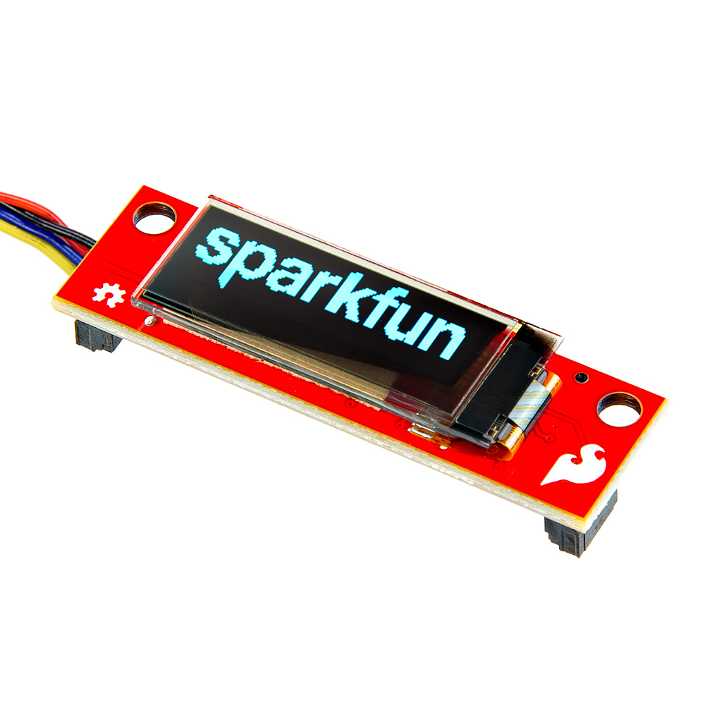
This sketch allows users to test the brightness of the WS2812 RGB LED on the RA6M5 Thing Plus in direct sunlight. The sketch implements an interrupt on the USRBTN button to increase the brightness of the LED in increments. The brightness value is then displayed on the Qwiic OLED Display, which is connected by a Qwiic cable.
Optional Hardware
The example code can be found in the GitHub repository. However, users can simply click the button to download the code or expand the box (below) to copy the code.
RGB_sunlight.ino
/*
  RGB_sunlight.ino

  ColorPalette.ino (Original)

  This example shows several ways to set up and use 'palettes' of colors
  with FastLED.

  These compact palettes provide an easy way to re-colorize your
  animation on the fly, quickly, easily, and with low overhead.

  USING palettes is MUCH simpler in practice than in theory, so first just
  run this sketch, and watch the pretty lights as you then read through
  the code.  Although this sketch has eight (or more) different color schemes,
  the entire sketch compiles down to about 6.5K on AVR.

  FastLED provides a few pre-configured color palettes, and makes it
  extremely easy to make up your own color schemes with palettes.

  Some notes on the more abstract 'theory and practice' of
  FastLED compact palettes are at the bottom of this file.

  Created: June 19, 2014 (Based on GitHub commit)
  Author: kriegsman

  ===========================================================================

  Used to test the WS2812 RGB LED on the RA6M5 Thing Plus in direct sunlight.
  The sketch implements an interrupt on the user button to increment the
  brightness of the LED. The brightness value is displayed on a Qwiic OLED
  Display (https://www.sparkfun.com/products/24606) connected by a Qwiic
  cable.

  Modified: April 11, 2024
  By SparkFun Electronics
  Author: Wes F
*/


#include <FastLED.h>              // http://librarymanager/All#FastLED
#include <SparkFun_Qwiic_OLED.h>  // http://librarymanager/All#SparkFun_Qwiic_OLED

QwiicNarrowOLED myOLED;           //

#define LED_PIN 13
#define NUM_LEDS 1
// #define BRIGHTNESS 60
#define LED_TYPE WS2812
#define COLOR_ORDER GRB
CRGB leds[NUM_LEDS];

#define UPDATES_PER_SECOND 100

CRGBPalette16 currentPalette;
TBlendType currentBlending;

extern CRGBPalette16 myRedWhiteBluePalette;
extern const TProgmemPalette16 myRedWhiteBluePalette_p PROGMEM;

int BRIGHTNESS = 75;

void setup() {
  delay(500);  // power-up safety delay
  FastLED.addLeds<LED_TYPE, LED_PIN, COLOR_ORDER>(leds, NUM_LEDS).setCorrection(TypicalLEDStrip);
  FastLED.setBrightness(BRIGHTNESS);
  pinMode(31, INPUT_PULLUP);
  attachInterrupt(digitalPinToInterrupt(31), ChangeBrightness, HIGH);

  currentPalette = RainbowColors_p;
  currentBlending = LINEARBLEND;
  Wire.begin();

  // Initalize the OLED device and related graphics system
  if (myOLED.begin() == false) {
    while (true)
      ;
  }
}


void loop() {
  FastLED.setBrightness(BRIGHTNESS);

  ChangePalettePeriodically();

  static uint8_t startIndex = 0;
  startIndex = startIndex + 1; /* motion speed */

  FillLEDsFromPaletteColors(startIndex);

  FastLED.show();
  FastLED.delay(1000 / UPDATES_PER_SECOND);

  myOLED.erase();
  myOLED.text(0, 0, "Brightness: " + String(BRIGHTNESS), 1);
  myOLED.display();
}

void ChangeBrightness() {
  BRIGHTNESS = BRIGHTNESS + 20;

  if (BRIGHTNESS > 255) {
    BRIGHTNESS = 75;
  }
}


void FillLEDsFromPaletteColors(uint8_t colorIndex) {
  uint8_t brightness = 255;

  for (int i = 0; i < NUM_LEDS; ++i) {
    leds[i] = ColorFromPalette(currentPalette, colorIndex, brightness, currentBlending);
    colorIndex += 3;
  }
}


// There are several different palettes of colors demonstrated here.
//
// FastLED provides several 'preset' palettes: RainbowColors_p, RainbowStripeColors_p,
// OceanColors_p, CloudColors_p, LavaColors_p, ForestColors_p, and PartyColors_p.
//
// Additionally, you can manually define your own color palettes, or you can write
// code that creates color palettes on the fly.  All are shown here.

void ChangePalettePeriodically() {
  uint8_t secondHand = (millis() / 1000) % 60;
  static uint8_t lastSecond = 99;

  if (lastSecond != secondHand) {
    lastSecond = secondHand;
    if (secondHand == 0) {
      currentPalette = RainbowColors_p;
      currentBlending = LINEARBLEND;
    }
    if (secondHand == 10) {
      currentPalette = RainbowStripeColors_p;
      currentBlending = NOBLEND;
    }
    if (secondHand == 15) {
      currentPalette = RainbowStripeColors_p;
      currentBlending = LINEARBLEND;
    }
    if (secondHand == 20) {
      SetupPurpleAndGreenPalette();
      currentBlending = LINEARBLEND;
    }
    if (secondHand == 25) {
      SetupTotallyRandomPalette();
      currentBlending = LINEARBLEND;
    }
    if (secondHand == 30) {
      SetupBlackAndWhiteStripedPalette();
      currentBlending = NOBLEND;
    }
    if (secondHand == 35) {
      SetupBlackAndWhiteStripedPalette();
      currentBlending = LINEARBLEND;
    }
    if (secondHand == 40) {
      currentPalette = CloudColors_p;
      currentBlending = LINEARBLEND;
    }
    if (secondHand == 45) {
      currentPalette = PartyColors_p;
      currentBlending = LINEARBLEND;
    }
    if (secondHand == 50) {
      currentPalette = myRedWhiteBluePalette_p;
      currentBlending = NOBLEND;
    }
    if (secondHand == 55) {
      currentPalette = myRedWhiteBluePalette_p;
      currentBlending = LINEARBLEND;
    }
  }
}

// This function fills the palette with totally random colors.
void SetupTotallyRandomPalette() {
  for (int i = 0; i < 16; ++i) {
    currentPalette[i] = CHSV(random8(), 255, random8());
  }
}

// This function sets up a palette of black and white stripes,
// using code.  Since the palette is effectively an array of
// sixteen CRGB colors, the various fill_* functions can be used
// to set them up.
void SetupBlackAndWhiteStripedPalette() {
  // 'black out' all 16 palette entries...
  fill_solid(currentPalette, 16, CRGB::Black);
  // and set every fourth one to white.
  currentPalette[0] = CRGB::White;
  currentPalette[4] = CRGB::White;
  currentPalette[8] = CRGB::White;
  currentPalette[12] = CRGB::White;
}

// This function sets up a palette of purple and green stripes.
void SetupPurpleAndGreenPalette() {
  CRGB purple = CHSV(HUE_PURPLE, 255, 255);
  CRGB green = CHSV(HUE_GREEN, 255, 255);
  CRGB black = CRGB::Black;

  currentPalette = CRGBPalette16(
    green, green, black, black,
    purple, purple, black, black,
    green, green, black, black,
    purple, purple, black, black);
}


// This example shows how to set up a static color palette
// which is stored in PROGMEM (flash), which is almost always more
// plentiful than RAM.  A static PROGMEM palette like this
// takes up 64 bytes of flash.
const TProgmemPalette16 myRedWhiteBluePalette_p PROGMEM = {
  CRGB::Red,
  CRGB::Gray,  // 'white' is too bright compared to red and blue
  CRGB::Blue,
  CRGB::Black,

  CRGB::Red,
  CRGB::Gray,
  CRGB::Blue,
  CRGB::Black,

  CRGB::Red,
  CRGB::Red,
  CRGB::Gray,
  CRGB::Gray,
  CRGB::Blue,
  CRGB::Blue,
  CRGB::Black,
  CRGB::Black
};


// Additional notes on FastLED compact palettes:
//
// Normally, in computer graphics, the palette (or "color lookup table")
// has 256 entries, each containing a specific 24-bit RGB color.  You can then
// index into the color palette using a simple 8-bit (one byte) value.
// A 256-entry color palette takes up 768 bytes of RAM, which on Arduino
// is quite possibly "too many" bytes.
//
// FastLED does offer traditional 256-element palettes, for setups that
// can afford the 768-byte cost in RAM.
//
// However, FastLED also offers a compact alternative.  FastLED offers
// palettes that store 16 distinct entries, but can be accessed AS IF
// they actually have 256 entries; this is accomplished by interpolating
// between the 16 explicit entries to create fifteen intermediate palette
// entries between each pair.
//
// So for example, if you set the first two explicit entries of a compact
// palette to Green (0,255,0) and Blue (0,0,255), and then retrieved
// the first sixteen entries from the virtual palette (of 256), you'd get
// Green, followed by a smooth gradient from green-to-blue, and then Blue.
For more information, please refer to the WS2812 datasheet and FastLED Arduino library.
Digital Input
Buttons are great for learning about digital inputs; and are often paired with LEDs, as a visual indicator for their operation.
Button - USRBTN
On the RA6M5 Thing Plus, the USRBTN button is the perfect component for operating a digital input. There are several built-in examples in the Arduino IDE for the basic use of a button as an input device. These examples utilize a digital intput to toggle an LED and/or generate an output text on the USB serial port. Users can find these sketches in the File > Examples > 01.Basics > DigitalReadSerial and File > Examples > 02.Digital drop-down menus.
DigitalReadSerial.inoButton.inoDebounce.inoInputPullupSerial.ino
Tip
Users will need to modify the sketches below, for the GPIO pin that is connected to the STAT LED and USRBTN. As previously, they can use the predefined LED_BUILTIN variable for the GPIO pin that is connected to the STAT LED. For the GPIO pin that is connected to the USRBTN, users till need to modify the pin to D31.
For more details, expand the boxes below to see the modifications that required to replace the highlighted values, in order to define the GPIO pins connected to the STAT LEDand USRBTN
USRBTN
DigitalReadSerial.ino
int pushButton = 2;
int pushButton = 31;
Button.ino and Debounce.ino
const int buttonPin = 2;  // the number of the pushbutton pin
const int buttonPin = 31;  // the number of the pushbutton pin
InputPullupSerial.ino
pinMode(2, INPUT_PULLUP);
pinMode(31, INPUT_PULLUP);

int sensorVal = digitalRead(2);
int sensorVal = digitalRead(31);
STAT LED
Button.ino and Debounce.ino
const int ledPin = 13;    // the number of the LED pin
const int ledPin = LED_BUILTIN;    // the number of the LED pin
InputPullupSerial.ino
pinMode(13, OUTPUT);
digitalWrite(13, value);

pinMode(LED_BUILTIN, OUTPUT);
digitalWrite(LED_BUILTIN, value);
Users can find this sketch in the File > Examples > 01.Basics > DigitalReadSerial drop-down menu.
DigitalReadSerial.ino
Users can find this sketch in the File > Examples > 02.Digital > Button drop-down menu.
Button.ino
Users can find this sketch in the File > Examples > 02.Digital > Debounce drop-down menu.
Debounce.ino
Users can find this sketch in the File > Examples > 02.Digital > InputPullupSerial drop-down menu.
InputPullupSerial.ino
Interrupts
The RA6M5 provides IRQ support on several of its digital input pins. This feature is great for creating an instantaneous response to a digital input, without having to wait for the MCU to complete its current task.
Code
const byte ledPin = LED_BUILTIN;
const byte interruptPin = 31;
volatile byte state = LOW;

void setup() {
  pinMode(ledPin, OUTPUT);
  pinMode(interruptPin, INPUT_PULLUP);
  attachInterrupt(digitalPinToInterrupt(interruptPin), blink, CHANGE);
}

void loop() {
  digitalWrite(ledPin, state);
}

void blink() {
  state = !state;
}
Arduino
In the Arduino IDE, interrupt requests are configured using the attachInterrupt(digitalPinToInterrupt(pin), ISR, mode) function, where:
pin- The GPIO pinISR- The interrupt service routine to call/execute when the interrupt occursmode- Defines how the interrupt should be triggered:LOW- When the pin is LOWCHANGE- Whenever the pin changes valueRISING- When the pin changes from LOW to HIGHFALLING- When the pin changes from HIGH to LOW
Warning
When utilizing an interrupt on a digital GPIO, the attached interrupt service routine should be able to execute within the shortest, possible time frame. Otherwise, the suspended task could trigger various faults or errors.
Examples - Analog I/O
Analog Input
The RA6M5 Thing Plus includes several breakout pins with access to the 12-bit ADC channels of the RA6M5. These feature is primarily used to record analog data from potentiometers and various sensors. For this example, users are free to utilize any hardware they have to connect the ADC from the A0 GPIO pins to an analog signal. We recommend selecting a device with a product manual that provides electrical diagrams and example code; below, are a few examples:
Optional Hardware
Below, are some basic example sketches for capturing analog data from generic devices such as a potentiometer or photocell.
Users can find this sketch in the File > Examples > 01.basics > AnalogReadSerial drop-down menu.
AnalogReadSerial.ino
Users can find this sketch in the File > Examples > 01.basics > ReadAnalogVoltage drop-down menu.
ReadAnalogVoltage.ino
Analog Output
AnalogWave Library
To implement the AnalogWave library from the Renesas Arduino core, users will need to link the library at the beginning of their sketch.
Once linked, users will need to create an instance of the analogWave class and declare a DAC pin for the output.
Tip
In the Renesas-Arduino core, DAC and DAC1 are predefined variables for their corresponding GPIO pins on the RA6M5 Thing Plus.
Below, are a few of the key methods available for the analogWave class:
Methods in analogWave.h
/* begin the output of the waweform the frequency is the one the complete
   set on sample are output (all samples will be output in 1 period */
bool begin(float freq_hz);
/* updated the frequency used */
bool freq(float freq_hz);
/* make the current index in the buffer to "jump" of the specified quantity */
void offset(uint32_t o);
/* start the generation of sample */
void start();
/* stop the genration of sample */
void stop();
/* every sample is multiplied for this factor must be a value between 0 and 1 */
void amplitude(float amplitude);


void sine(float freq_hz);
void square(float freq_hz);
void saw(float freq_hz);
For more information, please refer to the analogWave.cpp file in the AnalogWave library.
When generating an output signal from the DAC of the RA6M5 Thing Plus, users will need to define the waveform's type and frequency:
Oscilloscope
Oscilloscopes are the perfect tool to capture the waveform of a signal output. While useful, not all users will have access to this type of test equipment. For this example, user will need connect the probe from an oscilloscope to the DAC (A0) and GND GPIO pins.
Sine Wave
#include "analogWave.h" // Include the library for analog waveform generation

analogWave wave(DAC);   // Create an instance of the analogWave class, using the DAC pin

int freq = 60;  // in hertz, change accordingly

void setup() {
  wave.sine(freq);       // Generate a sine wave with the initial frequency
}

void loop() {}
Oscilloscope Adjustments
The DAC of the RA6M5, generates a waveform with a positive voltage. Therefore, user may need to adjust the vertical position of the probe's input channel.
Users may also find it helpful, to set the trigger on a discretized voltage step.
Feedback Loop
Another method to record the signal generated by the DAC, is with a jumper (wire) and looping a output signal from the DAC1 GPIO pin back into the A2 GPIO pin. While an oscilloscope is very useful, this is a more practical and cost-effective alternative for users. With this example, users are free to utilize any method or hardware they have to connect the DAC1 and A2 GPIO pins together. However, we recommend some IC hooks for a temporary connection.
Optional Hardware
After users have jumpered the GPIO pins and uploaded the example code, they will need to open the Serial Plotter in the Arduino IDE. Once opened, the tool will begin to plot the values that are received from the serial port. It should be noted that the Serial Plotter tool is unavailable in the legacy Arduino IDE v1.x.x; and some users may need to upgrade to the new Arduino IDE v2.x.x to access this tool. Additionally, the speed and buffer of the Serial Plotter tool are limiting factors in its performance. Therefore, careful consideration should be made when adjusting the waveform frequency and the delay intervals between readings.
Sine Wave
#include "analogWave.h" // Include the library for analog waveform generation

analogWave wave(DAC1);   // Create an instance of the analogWave class, using the DAC pin

int freq = 1;  // in hertz, change accordingly

void setup() {
  Serial.begin(115200);  // Initialize serial communication at a baud rate of 115200
  wave.sine(freq);       // Generate a sine wave with the initial frequency
}

void loop() {
  // Print the updated frequency to the serial monitor
  Serial.println(String(analogRead(A2)));
  delay(20);      // Delay for 20ms before repeating
}
Other Waveforms
Users can modify this example to generate other types of waveforms, as shown in the examples below.
Examples - Serial Port
Feedback Loop
The simplest way to test the UART interface is with just a jumper (wire) and looping transmission data from the TX GPIO pin; back into the RX GPIO pin. For this example, users are free to utilize any method or hardware they have to connect the RX and TX GPIO pins together. However, we recommend some IC hooks for a temporary connection.
Optional Hardware
After users have jumpered the GPIO pins and uploaded the example code, they will need to open the Serial Monitor in the Arduino IDE. Any entries that are sent through the message textbox, should be re-transmitted back into the Serial Monitor by the jumpered GPIO pins.
Users can find this sketch in the File > Examples > 04.Communication > MultiSerial drop-down menu.
MultiSerial.ino
Users can find this sketch in the File > Examples > 04.Communication > SerialPassthrough drop-down menu.
SerialPassthrough.ino
Peripheral Device
GNSS/GPS Module
For GNSS receivers, we recommend that the TinyGPSPlus Arduino library be utilized to parse the NMEA sentences from the module. Once the library is installed in the Arduino IDE, users will find several example sketches listed in the File > Examples > TinyGPSPlus > drop-down menu. We recommend the following examples for getting started with a GNSS receiver:
DeviceExample.inoFullExample.ino
Tip
Below, are a few tips for users to start working with the TinyGPSPlus Arduino library. However, for more details, users should refer to the documentation for the TinyGPSPlus Arduino library.
Define Parameters
When utilizing the examples in the TinyGPSPlus Arduino library, users may need to define and/or modify a few parameters. The baud rate for the GNSS receiver should be configured based upon the information presented in the datasheet.
For the RA6M5 Thing Plus, users have two options for configuring the serial port on the RX and TX GPIO pins:
- In the examples, they can continue to implement the SoftwareSerial library and update the values of
RXandTXGPIO pins in the code - Otherwise, users can remove the SoftwareSerial library implementation; and replace it with
Serial1UART port
-
Baud Rate
Check the datasheet or product manual for the default baud rate of the GPS receiver; if necessary, replace the value in the example:
static const uint32_t GPSBaud = 4800;
static const uint32_t GPSBaud = 115200;
In some cases, the datasheet may be inaccurate or the module's configuration was previously changed. In which case, the most common rates to try are:
4800bps9600bps115200bps
-
Update GPIO Pins
Replace the values for the
RX(D20) andTX(D21) GPIO pins for those on the RA6M5 Thing Plus:static const int RXPin =4, TXPin =3; static const int RXPin = 20, TXPin = 21; -
Utilize
Serial1Port
Remove the implementation of the SoftwareSerial library implementation
#include <SoftwareSerial.h>static const int RXPin = 4, TXPin = 3;SoftwareSerial ss(RXPin, TXPin);Then, replace the SoftwareSerial objects with
Serial1classvoid setup() { Serial.begin(115200);ssSerial1.begin(GPSBaud); void loop() { while (ssSerial1.available() > 0) if (gps.encode(ssSerial1.read())) displayInfo();
Hardware Assembly
Connecting a GNSS receiver to a microcontroller is relatively straight forward. Users must provide power to the module through the PWR/VCC and GND pins on the board. Additionally, the TX pin from the GNSS receiver, should be connected to the RX pin of the microcontroller. This will allow the module to transmit the NMEA sentences to the microcontroller.
| Thing Plus | GPS Module |
|---|---|
3V3 |
VCC or PWR |
GND |
GND |
RX (D21) |
TX |
TX (D20) |
--- |
Satellite Fix
As with all GNSS receivers, the module's antenna must have a clear view of the sky (it can't operate inside a building) to receive signal from the GNSS constellation. In addition, the GNSS receiver must acquire a fix on its position, before it starts transmitting complete NMEA sentences (with all the data).
Optional Hardware
After users have connected their GNSSS module and uploaded the example code, they will need to open the Serial Monitor in the Arduino IDE to view the data. Users should begin to see the data parsed by the TinyGPSPlus Arduino library, from the NMEA sentences transmitted from the GNSS receiver.
Users can find this sketch in the File > Examples > TinyGPSPlus > DeviceExample drop-down menu.
DeviceExample.ino
#include <TinyGPSPlus.h>
#include <SoftwareSerial.h>
/*
   This sample sketch demonstrates the normal use of a TinyGPSPlus (TinyGPSPlus) object.
   It requires the use of SoftwareSerial, and assumes that you have a
   4800-baud serial GPS device hooked up on pins 4(rx) and 3(tx).
*/
static const int RXPin = 4, TXPin = 3;
static const uint32_t GPSBaud = 4800;

// The TinyGPSPlus object
TinyGPSPlus gps;

// The serial connection to the GPS device
SoftwareSerial ss(RXPin, TXPin);

void setup()
{
  Serial.begin(115200);
  ss.begin(GPSBaud);

  Serial.println(F("DeviceExample.ino"));
  Serial.println(F("A simple demonstration of TinyGPSPlus with an attached GPS module"));
  Serial.print(F("Testing TinyGPSPlus library v. ")); Serial.println(TinyGPSPlus::libraryVersion());
  Serial.println(F("by Mikal Hart"));
  Serial.println();
}

void loop()
{
  // This sketch displays information every time a new sentence is correctly encoded.
  while (ss.available() > 0)
    if (gps.encode(ss.read()))
      displayInfo();

  if (millis() > 5000 && gps.charsProcessed() < 10)
  {
    Serial.println(F("No GPS detected: check wiring."));
    while(true);
  }
}

void displayInfo()
{
  Serial.print(F("Location: "));
  if (gps.location.isValid())
  {
    Serial.print(gps.location.lat(), 6);
    Serial.print(F(","));
    Serial.print(gps.location.lng(), 6);
  }
  else
  {
    Serial.print(F("INVALID"));
  }

  Serial.print(F("  Date/Time: "));
  if (gps.date.isValid())
  {
    Serial.print(gps.date.month());
    Serial.print(F("/"));
    Serial.print(gps.date.day());
    Serial.print(F("/"));
    Serial.print(gps.date.year());
  }
  else
  {
    Serial.print(F("INVALID"));
  }

  Serial.print(F(" "));
  if (gps.time.isValid())
  {
    if (gps.time.hour() < 10) Serial.print(F("0"));
    Serial.print(gps.time.hour());
    Serial.print(F(":"));
    if (gps.time.minute() < 10) Serial.print(F("0"));
    Serial.print(gps.time.minute());
    Serial.print(F(":"));
    if (gps.time.second() < 10) Serial.print(F("0"));
    Serial.print(gps.time.second());
    Serial.print(F("."));
    if (gps.time.centisecond() < 10) Serial.print(F("0"));
    Serial.print(gps.time.centisecond());
  }
  else
  {
    Serial.print(F("INVALID"));
  }

  Serial.println();
}
Users can find this sketch in the File > Examples > TinyGPSPlus* > FullExample drop-down menu.
FullExample.ino
#include <TinyGPSPlus.h>
#include <SoftwareSerial.h>
/*
   This sample code demonstrates the normal use of a TinyGPSPlus (TinyGPSPlus) object.
   It requires the use of SoftwareSerial, and assumes that you have a
   4800-baud serial GPS device hooked up on pins 4(rx) and 3(tx).
*/
static const int RXPin = 4, TXPin = 3;
static const uint32_t GPSBaud = 4800;

// The TinyGPSPlus object
TinyGPSPlus gps;

// The serial connection to the GPS device
SoftwareSerial ss(RXPin, TXPin);

void setup()
{
  Serial.begin(115200);
  ss.begin(GPSBaud);

  Serial.println(F("FullExample.ino"));
  Serial.println(F("An extensive example of many interesting TinyGPSPlus features"));
  Serial.print(F("Testing TinyGPSPlus library v. ")); Serial.println(TinyGPSPlus::libraryVersion());
  Serial.println(F("by Mikal Hart"));
  Serial.println();
  Serial.println(F("Sats HDOP  Latitude   Longitude   Fix  Date       Time     Date Alt    Course Speed Card  Distance Course Card  Chars Sentences Checksum"));
  Serial.println(F("           (deg)      (deg)       Age                      Age  (m)    --- from GPS ----  ---- to London  ----  RX    RX        Fail"));
  Serial.println(F("----------------------------------------------------------------------------------------------------------------------------------------"));
}

void loop()
{
  static const double LONDON_LAT = 51.508131, LONDON_LON = -0.128002;

  printInt(gps.satellites.value(), gps.satellites.isValid(), 5);
  printFloat(gps.hdop.hdop(), gps.hdop.isValid(), 6, 1);
  printFloat(gps.location.lat(), gps.location.isValid(), 11, 6);
  printFloat(gps.location.lng(), gps.location.isValid(), 12, 6);
  printInt(gps.location.age(), gps.location.isValid(), 5);
  printDateTime(gps.date, gps.time);
  printFloat(gps.altitude.meters(), gps.altitude.isValid(), 7, 2);
  printFloat(gps.course.deg(), gps.course.isValid(), 7, 2);
  printFloat(gps.speed.kmph(), gps.speed.isValid(), 6, 2);
  printStr(gps.course.isValid() ? TinyGPSPlus::cardinal(gps.course.deg()) : "*** ", 6);

  unsigned long distanceKmToLondon =
    (unsigned long)TinyGPSPlus::distanceBetween(
      gps.location.lat(),
      gps.location.lng(),
      LONDON_LAT,
      LONDON_LON) / 1000;
  printInt(distanceKmToLondon, gps.location.isValid(), 9);

  double courseToLondon =
    TinyGPSPlus::courseTo(
      gps.location.lat(),
      gps.location.lng(),
      LONDON_LAT,
      LONDON_LON);

  printFloat(courseToLondon, gps.location.isValid(), 7, 2);

  const char *cardinalToLondon = TinyGPSPlus::cardinal(courseToLondon);

  printStr(gps.location.isValid() ? cardinalToLondon : "*** ", 6);

  printInt(gps.charsProcessed(), true, 6);
  printInt(gps.sentencesWithFix(), true, 10);
  printInt(gps.failedChecksum(), true, 9);
  Serial.println();

  smartDelay(1000);

  if (millis() > 5000 && gps.charsProcessed() < 10)
    Serial.println(F("No GPS data received: check wiring"));
}

// This custom version of delay() ensures that the gps object
// is being "fed".
static void smartDelay(unsigned long ms)
{
  unsigned long start = millis();
  do
  {
    while (ss.available())
      gps.encode(ss.read());
  } while (millis() - start < ms);
}

static void printFloat(float val, bool valid, int len, int prec)
{
  if (!valid)
  {
    while (len-- > 1)
      Serial.print('*');
    Serial.print(' ');
  }
  else
  {
    Serial.print(val, prec);
    int vi = abs((int)val);
    int flen = prec + (val < 0.0 ? 2 : 1); // . and -
    flen += vi >= 1000 ? 4 : vi >= 100 ? 3 : vi >= 10 ? 2 : 1;
    for (int i=flen; i<len; ++i)
      Serial.print(' ');
  }
  smartDelay(0);
}

static void printInt(unsigned long val, bool valid, int len)
{
  char sz[32] = "*****************";
  if (valid)
    sprintf(sz, "%ld", val);
  sz[len] = 0;
  for (int i=strlen(sz); i<len; ++i)
    sz[i] = ' ';
  if (len > 0)
    sz[len-1] = ' ';
  Serial.print(sz);
  smartDelay(0);
}

static void printDateTime(TinyGPSDate &d, TinyGPSTime &t)
{
  if (!d.isValid())
  {
    Serial.print(F("********** "));
  }
  else
  {
    char sz[32];
    sprintf(sz, "%02d/%02d/%02d ", d.month(), d.day(), d.year());
    Serial.print(sz);
  }

  if (!t.isValid())
  {
    Serial.print(F("******** "));
  }
  else
  {
    char sz[32];
    sprintf(sz, "%02d:%02d:%02d ", t.hour(), t.minute(), t.second());
    Serial.print(sz);
  }

  printInt(d.age(), d.isValid(), 5);
  smartDelay(0);
}

static void printStr(const char *str, int len)
{
  int slen = strlen(str);
  for (int i=0; i<len; ++i)
    Serial.print(i<slen ? str[i] : ' ');
  smartDelay(0);
}
DA14531MOD
For the DA14531MOD, users can interface with the module through the Serial2 UART port of the RA6M5 Thing Plus. The firmware on the module implements the CodeLess AT command platform. This means, users can easily configure the BLE connectivity of the board with a few AT commands. For more details, please refer to the section with the DA14531MOD examples.
Examples - SPI Bus
Feedback Loop
The simplest way to test the SPI interface is with just a jumper (wire) and looping a data transmission from the PICO GPIO pin; back into the POCI GPIO pin. For this example, users are free to utilize any method or hardware they have to connect the PICO and POCI GPIO pins together. However, we recommend some IC hooks for a temporary connection.
Optional Hardware
SPI_Loopback.ino
#include <SPI.h>
#include <cstdint>

void setup()
{
    Serial.begin();
    while(!Serial) {delay(100);};

    Serial.println("SPI loopback test.");

    SPI.begin();
    SPI.beginTransaction(SPISettings(4000000, MSBFIRST, SPI_MODE1));

    testByteTransfer();

    testWordTransfer();

    testArrayTransfer();

    SPI.endTransaction();
    SPI.end();
}

void loop()
{

}

void testByteTransfer(void)
{
    const uint8_t testByte = 0b10100011;

    Serial.print("Sending: 0b");
    Serial.println(testByte, BIN);

    uint8_t recvByte = SPI.transfer(testByte);

    Serial.print("Received: 0b");
    Serial.println(recvByte, BIN);

    if (recvByte == testByte)
    {
        Serial.println("Byte loopback successful.");
    }
    else
    {
        Serial.println("Byte loopback unsuccessful. Please check logs.");
    }
}

void testWordTransfer(void)
{
    const uint8_t testWord = 0b1111000010100101;

    Serial.print("Sending: 0b");
    Serial.println(testWord, BIN);

    uint8_t recvWord = SPI.transfer(testWord);

    Serial.print("Received: 0b");
    Serial.println(recvWord, BIN);

    if (recvWord == testWord)
    {
        Serial.println("Word loopback successful.");
    }
    else
    {
        Serial.println("Word loopback unsuccessful. Please check logs.");
    }
}

void testArrayTransfer(void)
{
    const uint8_t numel = 18;

    uint8_t *data = (uint8_t*)malloc(numel);

    uint8_t *data_ptr = data;

    for(uint8_t i = 0; i < numel; ++i)
    {
        *data_ptr++ = i;
    }

    SPI.transfer(data, numel);

    data_ptr = data;

    /* 0 is inital expected results, 255 is when pin is open
     so initialse result variable to 111 to make it clear the value has changed. */
    uint8_t result = 111;

    Serial.println();
    Serial.println("Multiple byte transfer test");
    Serial.println("element value result");

    for(uint8_t i = 0; i< numel; ++i)
    {
        result = *data_ptr++;
        Serial.print(i);
        Serial.print("\t");
        Serial.print(result);
        Serial.print("\t");

        if(result == i)
        {
            Serial.println("pass");
        }
        else
        {
            Serial.println("fail");
        }
    }
}
Peripheral Device
A more direct method for testing the SPI interface is with an actual SPI device.
BME688 Environmental Sensor
Users are free to utilize any hardware they already have; however, we recommend the BME688 environmental sensor, below. Its SPI pins are broken out on the edge of the board and can be easily connected to the RA6M5 Thing Plus. In addition, a hookup guide and Arduino library for the sensor are available.
Optional Hardware
Install Arduino Library
Users will need to install the Bosch BME68x Arduino library for the sensor. In the Arduino IDE, users can install it by searching for BME68x Sensor Library, in the Library Manager:
BME68x Sensor Library
Users can find this sketch in the File > Examples > BME68x Sensor library > forced_mode drop-down menu. For more details on utilizing the BME68x breakout board, please refer to our hookup guide for the sensor.
forced_mode.ino
/**
 * Copyright (C) 2021 Bosch Sensortec GmbH
 *
 * SPDX-License-Identifier: BSD-3-Clause
 *
 */

#include "Arduino.h"
#include "bme68xLibrary.h"

#ifndef PIN_CS
#define PIN_CS SS
#endif

Bme68x bme;

/**
 * @brief Initializes the sensor and hardware settings
 */
void setup(void)
{
    SPI.begin();
    Serial.begin(115200);

    while (!Serial)
        delay(10);

    /* initializes the sensor based on SPI library */
    bme.begin(PIN_CS, SPI);

    if(bme.checkStatus())
    {
        if (bme.checkStatus() == BME68X_ERROR)
        {
            Serial.println("Sensor error:" + bme.statusString());
            return;
        }
        else if (bme.checkStatus() == BME68X_WARNING)
        {
            Serial.println("Sensor Warning:" + bme.statusString());
        }
    }

    /* Set the default configuration for temperature, pressure and humidity */
    bme.setTPH();

    /* Set the heater configuration to 300 deg C for 100ms for Forced mode */
    bme.setHeaterProf(300, 100);

    Serial.println("TimeStamp(ms), Temperature(deg C), Pressure(Pa), Humidity(%), Gas resistance(ohm), Status");
}

void loop(void)
{
    bme68xData data;

    bme.setOpMode(BME68X_FORCED_MODE);
    delayMicroseconds(bme.getMeasDur());

    if (bme.fetchData())
    {
        bme.getData(data);
        Serial.print(String(millis()) + ", ");
        Serial.print(String(data.temperature) + ", ");
        Serial.print(String(data.pressure) + ", ");
        Serial.print(String(data.humidity) + ", ");
        Serial.print(String(data.gas_resistance) + ", ");
        Serial.println(data.status, HEX);
    }
}
Examples - I2C Bus
Device Scan
This sketch allows users to scan for devices connected to the primary I2C bus of the RAM5 Thing Plus. The example code can be found in the GitHub repository. However, users can also simply click on the button (below), to download the code; or expand the box (below), to copy the code.
i2c_scanner.ino
// --------------------------------------
// i2c_scanner
//
// Modified from https://playground.arduino.cc/Main/I2cScanner/
// --------------------------------------

#include <Wire.h>

// Set I2C bus to use: Wire, Wire1, etc.
#define WIRE Wire

int toggle = 0;

void setup() {
  WIRE.begin();

  pinMode(8, OUTPUT);

  Serial.begin(115200);
  while (!Serial)
    delay(10);
  Serial.println("\nI2C Scanner");
}


void loop() {
  if (toggle == 0) {
    digitalWrite(8, HIGH);
    toggle = 1;
  } else {
    digitalWrite(8, LOW);
    toggle = 0;
  }


  byte error, address;
  int nDevices;

  Serial.println("Scanning...");

  nDevices = 0;
  for (address = 1; address < 127; address++) {
    // The i2c_scanner uses the return value of
    // the Write.endTransmisstion to see if
    // a device did acknowledge to the address.
    WIRE.beginTransmission(address);
    error = WIRE.endTransmission();

    if (error == 0) {
      Serial.print("I2C device found at address 0x");
      if (address < 16)
        Serial.print("0");
      Serial.print(address, HEX);
      Serial.println("  !");

      nDevices++;
    } else if (error == 4) {
      Serial.print("Unknown error at address 0x");
      if (address < 16)
        Serial.print("0");
      Serial.println(address, HEX);
    }
  }
  if (nDevices == 0)
    Serial.println("No I2C devices found\n");
  else
    Serial.println("done\n");

  delay(700);  // wait 5 seconds for next scan
}
Peripheral Devices
The RA6M5 Thing Plus features a Qwiic connector to seamlessly integrate with devices from SparkFun's Qwiic Ecosystem. While users are free to utilize any I2C device, we recommend the Qwiic devices from our catalog.
Optional Hardware
-
SparkFun Qwiic Cable Kit
KIT-15081 -
Qwiic Cable - Grove Adapter (100mm)
PRT-15109 -
SparkFun Qwiic OLED - (1.3in., 128x64)
LCD-23453 -
SparkFun GPS Breakout - XA1110 (Qwiic)
GPS-14414 -
SparkFun Qwiic Joystick
COM-15168 -
SparkFun Qwiic Mux Breakout - 8 Channel (TCA9548A)
BOB-16784 -
SparkFun Environmental Sensor - BME688 (Qwiic)
SEN-19096 -
SparkFun Qwiic Mini ToF Imager - VL53L5CX
SEN-19013
MAX17048 Fuel Gauge
The MAX17048 fuel gauge measures the approximate charge/discharge rate, state of charge, and voltage of a connected LiPo battery. We recommend the SparkFun MAX1704x Arduino library be utilized in the Arduino IDE, to connect to the MAX17048 on the RA6M5 Thing Plus. Once the library is installed in the Arduino IDE, users will find several example sketches listed in the File > Examples > SparkFun MAX1704x Fuel Gauge Arduino Library > drop-down menu. We recommend the following examples for users:
Example1_Simple.inoExample4_MAX17048_KitchenSink.ino
Optional Hardware
Users can find this sketch in the File > Examples > SparkFun MAX1704x Fuel Gauge Arduino Library > Example1_Simple drop-down menu.
Example1_Simple.ino
/******************************************************************************
Example1_Simple
By: Paul Clark
Date: October 23rd 2020

Based extensively on:
MAX17043_Simple_Serial.cpp
SparkFun MAX17043 Example Code
Jim Lindblom @ SparkFun Electronics
Original Creation Date: June 22, 2015

This file demonstrates the simple API of the SparkFun MAX17043 Arduino library.

This example will print the gauge's voltage and state-of-charge (SOC) readings
to Serial (115200 baud)

This code is released under the MIT license.

Distributed as-is; no warranty is given.
******************************************************************************/

#include <Wire.h> // Needed for I2C

#include <SparkFun_MAX1704x_Fuel_Gauge_Arduino_Library.h> // Click here to get the library: http://librarymanager/All#SparkFun_MAX1704x_Fuel_Gauge_Arduino_Library

SFE_MAX1704X lipo; // Defaults to the MAX17043

//SFE_MAX1704X lipo(MAX1704X_MAX17043); // Create a MAX17043
//SFE_MAX1704X lipo(MAX1704X_MAX17044); // Create a MAX17044
//SFE_MAX1704X lipo(MAX1704X_MAX17048); // Create a MAX17048
//SFE_MAX1704X lipo(MAX1704X_MAX17049); // Create a MAX17049

double voltage = 0; // Variable to keep track of LiPo voltage
double soc = 0; // Variable to keep track of LiPo state-of-charge (SOC)
bool alert; // Variable to keep track of whether alert has been triggered

void setup()
{
    Serial.begin(115200); // Start serial, to output debug data
  while (!Serial)
    ; //Wait for user to open terminal
  Serial.println(F("MAX17043 Example"));

  Wire.begin();

  lipo.enableDebugging(); // Uncomment this line to enable helpful debug messages on Serial

  // Set up the MAX17043 LiPo fuel gauge:
  if (lipo.begin() == false) // Connect to the MAX17043 using the default wire port
  {
    Serial.println(F("MAX17043 not detected. Please check wiring. Freezing."));
    while (1)
      ;
  }

    // Quick start restarts the MAX17043 in hopes of getting a more accurate
    // guess for the SOC.
    lipo.quickStart();

    // We can set an interrupt to alert when the battery SoC gets too low.
    // We can alert at anywhere between 1% - 32%:
    lipo.setThreshold(20); // Set alert threshold to 20%.
}

void loop()
{
  // lipo.getVoltage() returns a voltage value (e.g. 3.93)
  voltage = lipo.getVoltage();
  // lipo.getSOC() returns the estimated state of charge (e.g. 79%)
  soc = lipo.getSOC();
  // lipo.getAlert() returns a 0 or 1 (0=alert not triggered)
  alert = lipo.getAlert();

  // Print the variables:
  Serial.print("Voltage: ");
  Serial.print(voltage);  // Print the battery voltage
  Serial.println(" V");

  Serial.print("Percentage: ");
  Serial.print(soc); // Print the battery state of charge
  Serial.println(" %");

  Serial.print("Alert: ");
  Serial.println(alert);
  Serial.println();

  delay(500);
}
Users can find this sketch in the File > Examples > SparkFun MAX1704x Fuel Gauge Arduino Library > Example4_MAX17048_KitchenSink drop-down menu.
Example4_MAX17048_KitchenSink.ino
/******************************************************************************
Example4: test all the things on the MAX17048
By: Paul Clark, SparkFun Electronics
Date: October 23rd 2020

This example is an everything-but-the-kitchen-sink test of the MAX17048.

This code is released under the MIT license.

Distributed as-is; no warranty is given.
******************************************************************************/

#include <Wire.h> // Needed for I2C

#include <SparkFun_MAX1704x_Fuel_Gauge_Arduino_Library.h> // Click here to get the library: http://librarymanager/All#SparkFun_MAX1704x_Fuel_Gauge_Arduino_Library

SFE_MAX1704X lipo(MAX1704X_MAX17048); // Create a MAX17048

void setup()
{
    Serial.begin(115200); // Start serial, to output debug data
  while (!Serial)
    ; //Wait for user to open terminal
  Serial.println(F("MAX17048 Example"));

  Wire.begin();

  lipo.enableDebugging(); // Uncomment this line to enable helpful debug messages on Serial

  // Set up the MAX17048 LiPo fuel gauge:
  if (lipo.begin() == false) // Connect to the MAX17048 using the default wire port
  {
    Serial.println(F("MAX17048 not detected. Please check wiring. Freezing."));
    while (1)
      ;
  }

  // Just because we can, let's reset the MAX17048
  Serial.println(F("Resetting the MAX17048..."));
  delay(1000); // Give it time to get its act back together

  // Read and print the reset indicator
  Serial.print(F("Reset Indicator was: "));
  bool RI = lipo.isReset(true); // Read the RI flag and clear it automatically if it is set
  Serial.println(RI); // Print the RI
  // If RI was set, check it is now clear
  if (RI)
  {
    Serial.print(F("Reset Indicator is now: "));
    RI = lipo.isReset(); // Read the RI flag
    Serial.println(RI); // Print the RI
  }

  // To quick-start or not to quick-start? That is the question!
  // Read the following and then decide if you do want to quick-start the fuel gauge.
  // "Most systems should not use quick-start because the ICs handle most startup problems transparently,
  //  such as intermittent battery-terminal connection during insertion. If battery voltage stabilizes
  //  faster than 17ms then do not use quick-start. The quick-start command restarts fuel-gauge calculations
  //  in the same manner as initial power-up of the IC. If the system power-up sequence is so noisy that the
  //  initial estimate of SOC has unacceptable error, the system microcontroller might be able to reduce the
  //  error by using quick-start."
  // If you still want to try a quick-start then uncomment the next line:
    //lipo.quickStart();

  // Read and print the device ID
  Serial.print(F("Device ID: 0x"));
  uint8_t id = lipo.getID(); // Read the device ID
  if (id < 0x10) Serial.print(F("0")); // Print the leading zero if required
  Serial.println(id, HEX); // Print the ID as hexadecimal

  // Read and print the device version
  Serial.print(F("Device version: 0x"));
  uint8_t ver = lipo.getVersion(); // Read the device version
  if (ver < 0x10) Serial.print(F("0")); // Print the leading zero if required
  Serial.println(ver, HEX); // Print the version as hexadecimal

  // Read and print the battery threshold
  Serial.print(F("Battery empty threshold is currently: "));
  Serial.print(lipo.getThreshold());
  Serial.println(F("%"));

    // We can set an interrupt to alert when the battery SoC gets too low.
    // We can alert at anywhere between 1% and 32%:
    lipo.setThreshold(20); // Set alert threshold to 20%.

  // Read and print the battery empty threshold
  Serial.print(F("Battery empty threshold is now: "));
  Serial.print(lipo.getThreshold());
  Serial.println(F("%"));

  // Read and print the high voltage threshold
  Serial.print(F("High voltage threshold is currently: "));
  float highVoltage = ((float)lipo.getVALRTMax()) * 0.02; // 1 LSb is 20mV. Convert to Volts.
  Serial.print(highVoltage, 2);
  Serial.println(F("V"));

  // Set the high voltage threshold
  lipo.setVALRTMax((float)4.1); // Set high voltage threshold (Volts)

  // Read and print the high voltage threshold
  Serial.print(F("High voltage threshold is now: "));
  highVoltage = ((float)lipo.getVALRTMax()) * 0.02; // 1 LSb is 20mV. Convert to Volts.
  Serial.print(highVoltage, 2);
  Serial.println(F("V"));

  // Read and print the low voltage threshold
  Serial.print(F("Low voltage threshold is currently: "));
  float lowVoltage = ((float)lipo.getVALRTMin()) * 0.02; // 1 LSb is 20mV. Convert to Volts.
  Serial.print(lowVoltage, 2);
  Serial.println(F("V"));

  // Set the low voltage threshold
  lipo.setVALRTMin((float)3.9); // Set low voltage threshold (Volts)

  // Read and print the low voltage threshold
  Serial.print(F("Low voltage threshold is now: "));
  lowVoltage = ((float)lipo.getVALRTMin()) * 0.02; // 1 LSb is 20mV. Convert to Volts.
  Serial.print(lowVoltage, 2);
  Serial.println(F("V"));

  // Enable the State Of Change alert
  Serial.print(F("Enabling the 1% State Of Change alert: "));
  if (lipo.enableSOCAlert())
  {
    Serial.println(F("success."));
  }
  else
  {
    Serial.println(F("FAILED!"));
  }

  // Read and print the HIBRT Active Threshold
  Serial.print(F("Hibernate active threshold is: "));
  float actThr = ((float)lipo.getHIBRTActThr()) * 0.00125; // 1 LSb is 1.25mV. Convert to Volts.
  Serial.print(actThr, 5);
  Serial.println(F("V"));

  // Read and print the HIBRT Hibernate Threshold
  Serial.print(F("Hibernate hibernate threshold is: "));
  float hibThr = ((float)lipo.getHIBRTHibThr()) * 0.208; // 1 LSb is 0.208%/hr. Convert to %/hr.
  Serial.print(hibThr, 3);
  Serial.println(F("%/h"));
}

void loop()
{
  // Print the variables:
  Serial.print("Voltage: ");
  Serial.print(lipo.getVoltage());  // Print the battery voltage
  Serial.print("V");

  Serial.print(" Percentage: ");
  Serial.print(lipo.getSOC(), 2); // Print the battery state of charge with 2 decimal places
  Serial.print("%");

  Serial.print(" Change Rate: ");
  Serial.print(lipo.getChangeRate(), 2); // Print the battery change rate with 2 decimal places
  Serial.print("%/hr");

  Serial.print(" Alert: ");
  Serial.print(lipo.getAlert()); // Print the generic alert flag

  Serial.print(" Voltage High Alert: ");
  Serial.print(lipo.isVoltageHigh()); // Print the alert flag

  Serial.print(" Voltage Low Alert: ");
  Serial.print(lipo.isVoltageLow()); // Print the alert flag

  Serial.print(" Empty Alert: ");
  Serial.print(lipo.isLow()); // Print the alert flag

  Serial.print(" SOC 1% Change Alert: ");
  Serial.print(lipo.isChange()); // Print the alert flag

  Serial.print(" Hibernating: ");
  Serial.print(lipo.isHibernating()); // Print the alert flag

  Serial.println();

  delay(500);
}
BME688 Environmental Sensor
Users are free to utilize any hardware they already have; however, we recommend the BME688 environmental sensor. The board includes a Qwiic connector on the edge of the board and can be easily attached to the RA6M5 Thing Plus with a Qwiic cable. In addition, a hookup guide and Arduino library for the sensor are available.
Optional Hardware
Install Arduino Library
Users will need to install the Bosch BME68x Arduino library for the sensor. In the Arduino IDE, users can install it by searching for BME68x Sensor Library, in the Library Manager:
BME68x Sensor Library
Users can find this sketch in the File > Examples > BME68x Sensor library > forced_mode drop-down menu. For more details on utilizing the BME68x breakout board, please refer to our hookup guide for the sensor.
forced_mode.ino
I2C Modifications
By default, this example utilizes the SPI bus; therefore, some modifications must be made:
-
The chip select pin no longer needs to be defined:
#ifndef PIN_CS #define PIN_CS SS #endif -
The I2C bus must be initialized, instead of the SPI bus:
SPI.begin();Wire.begin(); -
The sensor must be initialized with the Wire class, instead of the SPI class:
/* initializes the sensor based onSPIWire library */bme.begin(PIN_CS, SPI);bme.begin(BME68X_I2C_ADDR_LOW, Wire)
/**
 * Copyright (C) 2021 Bosch Sensortec GmbH
 *
 * SPDX-License-Identifier: BSD-3-Clause
 *
 */

#include "Arduino.h"
#include "bme68xLibrary.h"

#ifndef PIN_CS
#define PIN_CS SS
#endif

Bme68x bme;

/**
 * @brief Initializes the sensor and hardware settings
 */
void setup(void)
{
    SPI.begin();
    Serial.begin(115200);

    while (!Serial)
        delay(10);

    /* initializes the sensor based on SPI library */
    bme.begin(PIN_CS, SPI);

    if(bme.checkStatus())
    {
        if (bme.checkStatus() == BME68X_ERROR)
        {
            Serial.println("Sensor error:" + bme.statusString());
            return;
        }
        else if (bme.checkStatus() == BME68X_WARNING)
        {
            Serial.println("Sensor Warning:" + bme.statusString());
        }
    }

    /* Set the default configuration for temperature, pressure and humidity */
    bme.setTPH();

    /* Set the heater configuration to 300 deg C for 100ms for Forced mode */
    bme.setHeaterProf(300, 100);

    Serial.println("TimeStamp(ms), Temperature(deg C), Pressure(Pa), Humidity(%), Gas resistance(ohm), Status");
}

void loop(void)
{
    bme68xData data;

    bme.setOpMode(BME68X_FORCED_MODE);
    delayMicroseconds(bme.getMeasDur());

    if (bme.fetchData())
    {
        bme.getData(data);
        Serial.print(String(millis()) + ", ");
        Serial.print(String(data.temperature) + ", ");
        Serial.print(String(data.pressure) + ", ");
        Serial.print(String(data.humidity) + ", ");
        Serial.print(String(data.gas_resistance) + ", ");
        Serial.println(data.status, HEX);
    }
}
Examples - Memory/Storage
Data Corruption
To avoid any data loss or corrupting the SD card, users should disable all activity with the SD card before removing it from the RA6M5 Thing Plus.
The FATFileSystem library built into the Renesas-Arduino core, supports µSD cards with a FAT32 file system (i.e. SD cards up to 32GB in size).
- While users may be able to use cards with a higher storage capacity, we highly advise against it. As users may experience data loss due to a corrupt file system (i.e. SD cards with a storage capacity greater than 32GB are not meant to be formatted with a FAT32 file system).
SD Card - Test
The Renesas-Arduino core includes a built-in FATFileSystem library that controls the SD host interface. The library that supports SD cards with a FAT32 file system (i.e. SD cards up to 32GB in size). Users can find an example sketch in the File > Examples > Storage > TestSDCARD drop-down menu.
Optional Hardware
TestSDCARD.ino
/*
  Portenta H33 - TestSDCARD with Fat FS

  The sketch shows how to mount an SDCARD and list its content.

  The circuit:
   - Portenta H33 + Portenta Breakout

  created January 31th, 2023
  by Daniele Aimo

  This example code is in the public domain.
*/

#include <vector>
#include <string>
#include "SDCardBlockDevice.h"
#include "FATFileSystem.h"

#define TEST_FS_NAME "fs"
#define TEST_FOLDER_NAME "TEST_FOLDER"
#define TEST_FILE "test.txt"
#define DELETE_FILE_DIMENSION 150


SDCardBlockDevice block_device(PIN_SDHI_CLK, PIN_SDHI_CMD, PIN_SDHI_D0, PIN_SDHI_D1, PIN_SDHI_D2, PIN_SDHI_D3, PIN_SDHI_CD, PIN_SDHI_WP);
FATFileSystem fs(TEST_FS_NAME);

std::string root_folder       = std::string("/") + std::string(TEST_FS_NAME);
std::string folder_test_name  = root_folder + std::string("/") + std::string(TEST_FOLDER_NAME);
std::string file_test_name    = folder_test_name + std::string("/") + std::string(TEST_FILE);

void setup() {
  /*
   *  SERIAL INITIALIZATION
   */
  Serial.begin(9600);
  while(!Serial) {

  }

  /* list to store all directory in the root */
  std::vector<std::string> dir_list;

  Serial.println();
  Serial.println("##### TEST SD CARD with FAT FS");
  Serial.println();

  /*
   *  MOUNTING SDCARD AS FATFS filesystem
   */
  Serial.println("Mounting SDCARD...");
  int err =  fs.mount(&block_device);
  if (err) {
    // Reformat if we can't mount the filesystem
    // this should only happen on the first boot
    Serial.println("No filesystem found, formatting... ");
    err = fs.reformat(&block_device);
  }
  if (err) {
     Serial.println("Error formatting SDCARD ");
     while(1);
  }

  /*
   *  READING root folder
   */

  DIR *dir;
  struct dirent *ent;
  int dirIndex = 0;

  Serial.println("*** List SD CARD content: ");
  if ((dir = opendir(root_folder.c_str())) != NULL) {
    while ((ent = readdir (dir)) != NULL) {

      if(ent->d_type == DT_REG) {
        Serial.print("- [File]: ");
      }

      else if(ent->d_type == DT_DIR) {
        Serial.print("- [Fold]: ");
        dir_list.push_back(ent->d_name);
      }
      Serial.println(ent->d_name);
      dirIndex++;
    }
    closedir (dir);
  }
  else {
    // Could not open directory
    Serial.println("Error opening SDCARD\n");
    while(1);
  }

  if(dirIndex == 0) {
    Serial.println("Empty SDCARD");
  }

  bool found_test_folder = false;

  /*
   *  LISTING CONTENT of the first level folders (the one immediately present in root folder)
   */

  if(dir_list.size()) {
    Serial.println();
    Serial.println("Listing content of folders in root: ");
  }
  for(unsigned int i = 0; i < dir_list.size(); i++) {
    if(dir_list[i] == TEST_FOLDER_NAME) {
      found_test_folder = true;
    }
    Serial.print("- ");
    Serial.print(dir_list[i].c_str());
    Serial.println(":");

    std::string d = root_folder + std::string("/") + dir_list[i];
    if ((dir = opendir(d.c_str())) != NULL) {
      while ((ent = readdir (dir)) != NULL) {
        if(ent->d_type == DT_REG) {
          Serial.print("   - [File]: ");
        }
        else if(ent->d_type == DT_DIR) {
          Serial.print("   - [Fold]: ");
        }
        Serial.println(ent->d_name);
      }
      closedir (dir);
    }
    else {
      Serial.print("ERROR OPENING SUB-FOLDER ");
      Serial.println(d.c_str());
    }
  }

  /*
   *  CREATING TEST FOLDER (if does not exist already)
   */

  err = 0;
  if(!found_test_folder) {
    Serial.println("TEST FOLDER NOT FOUND... creating folder test");
    err = mkdir(folder_test_name.c_str(), S_IRWXU | S_IRWXG | S_IRWXO);
    if(err != 0) {
      Serial.print("FAILED folder creation with error ");
      Serial.println(err);
    }
  }

  /*
   *  READING TEST FILE CONTENT
   */

  if(err == 0) {
    int file_dimension = 0;
    FILE* fp = fopen(file_test_name.c_str(), "r");
    if(fp != NULL) {
      Serial.print("Opened file: ");
      Serial.print(file_test_name.c_str());
      Serial.println(" for reading");

      fseek(fp, 0L, SEEK_END);
      int numbytes = ftell(fp);
      fseek(fp, 0L, SEEK_SET);

      Serial.print("Bytes in the file: ");
      Serial.println(numbytes);
      file_dimension = numbytes;

      if(numbytes > 0) {
        Serial.println();
        Serial.println("-------------------- START FILE CONTENT --------------------");
      }

      for(int i = 0; i < numbytes; i++) {
        char ch;
        fread(&ch, sizeof(char), 1, fp);
        Serial.print(ch);
      }

      if(numbytes > 0) {
        Serial.println("--------------------- END FILE CONTENT ---------------------");
        Serial.println();
      }
      else {
        Serial.println("File is EMPTY!");
        Serial.println();
      }

      fclose(fp);
    }
    else {
      Serial.print("FAILED open file ");
      Serial.println(file_test_name.c_str());
    }

    /*
     * DELETE FILE IF THE File dimension is greater than 150 bytes
     */

    if(file_dimension > DELETE_FILE_DIMENSION) {
      Serial.println("Test file reached the delete dimension... deleting it!");
      if(remove(file_test_name.c_str()) == 0) {
        Serial.println("TEST FILE HAS BEEN DELETED!");
      }
    }

    /*
     * APPENDING SOMETHING TO FILE
     */

    fp = fopen(file_test_name.c_str(), "a");
    if(fp != NULL) {
      Serial.print("Opened file: ");
      Serial.print(file_test_name.c_str());
      Serial.println(" for writing (append)");
      char text[] = "This line has been appended to file!\n";
      fwrite(text, sizeof(char), strlen(text), fp);
      fclose(fp);
    }
    else {
      Serial.print("FAILED open file for appending ");
      Serial.println(file_test_name.c_str());
    }

    /*
     * READING AGAIN FILE CONTENT
     */

    fp = fopen(file_test_name.c_str(), "r");
    if(fp != NULL) {
      Serial.print("Opened file: ");
      Serial.print(file_test_name.c_str());
      Serial.println(" for reading");

      fseek(fp, 0L, SEEK_END);
      int numbytes = ftell(fp);
      fseek(fp, 0L, SEEK_SET);

      Serial.print("Bytes in the file: ");
      Serial.println(numbytes);

      if(numbytes > 0) {
        Serial.println();
        Serial.println("-------------------- START FILE CONTENT --------------------");
      }

      for(int i = 0; i < numbytes; i++) {
        char ch;
        fread(&ch, sizeof(char), 1, fp);
        Serial.print(ch);
      }

      if(numbytes > 0) {
        Serial.println("--------------------- END FILE CONTENT ---------------------");
        Serial.println();
      }
      else {
        Serial.println("File is EMPTY!");
        Serial.println();
      }

      fclose(fp);

    }
    else {
      Serial.print("FAILED open file for appending ");
      Serial.println(file_test_name.c_str());
    }
  }

}

void loop() {
  // Empty
}
MX25L12833F
The Renesas-Arduino core includes a built-in FATFileSystem library to control the QSPI flash memory. This example code demonstrates how to initialize the flash memory, a file is written, and data is read from the file. Users can also find other example sketches in the File > Examples > Storage drop-down menu.
QSPI_Flash_FileSystem_Test.ino
ESLOV Connector
The Portenta C33 board features an onboard ESLOV connector to extend the I2C communication bus. This connector simplifies connecting various sensors, actuators, and other modules to the Portenta C33 without soldering or wiring; Nicla family boards can also be connected to the Portenta C33 through this connector.

The ESLOV connector is a small 5-pin connector with a 1.00 mm pitch. The mechanical details of the connector can be found in the connector's datasheet.
The pin layout of the ESLOV connector is the following:
- VCC
- INT
- SCL
- SDA
- GND
VCC pin works as a 5 V output if the board is connected to a USB-C® cable. The manufacturer part number of the ESLOV connector is SM05B-SRSS, and its matching receptacle manufacturer part number is SHR-05V-S-B.
External Memory
The Portenta C33 board features an onboard 16 MB QSPI Flash memory, the MX25L12833F from Macronix®. Having an onboard QSPI Flash memory enhances the capabilities of the Portenta C33, enabling you to develop and run more complex and data-intensive applications.

Some key advantages of having an onboard QSPI Flash memory are the following:
- Storage capacity: The MX25L12833F QSPI Flash memory adds significant non-volatile storage to the board.
- Extended functionality: The additional memory space allows more complex applications to be developed and run on your Portenta C33. This application includes data logging, image processing, audio processing, and executing complex algorithms.
- Firmware updates: The MX25L12833F QSPI Flash memory can also store firmware or software updates for your Arduino board. This means you can update the firmware without requiring a complete reprogramming of the board.
The Arduino Renesas Core has built-in libraries and drivers that immediately let you use the onboard QSPI Flash memory. Let's walk through an example code demonstrating some of the onboard Flash memory capabilities; the main tasks performed in the sketch are initializing the Flash memory, writing to a file, and reading from a file.
```arduino /** QSPI Flash File System test Name: QSPI_Flash_FileSystem_Test.ino Purpose: This sketch test the onboard QSPI Flash memory file system by writing and reading a file.
@author Arduino Team @version 1.0 20/06/23 */
// Include necessary libraries and drivers
include "QSPIFlashBlockDevice.h"
include "FATFileSystem.h"
// Define constants for file system and test file name
define QSPI_FS_NAME "qspi"
define TEST_FILE "test.txt"
// Instantiate flash block device and file system QSPIFlashBlockDevice block_device(PIN_QSPI_CLK, PIN_QSPI_SS, PIN_QSPI_D0, PIN_QSPI_D1, PIN_QSPI_D2, PIN_QSPI_D3); FATFileSystem fs(QSPI_FS_NAME);
// Define full path to the test file std::string file_test_name = std::string("/") + std::string(QSPI_FS_NAME) + std::string("/") + std::string(TEST_FILE);
void setup() { // Initialize serial communication and wait a connection Serial.begin(9600); while(!Serial);
// Print test start message Serial.println(); Serial.println("- SIMPLE QSPI FLASH TEST"); Serial.println();
// Try to mount the QSPI Flash file system // If mounting fails, try to format the file system int err = fs.mount(&block_device); if (err) { Serial.println("- No filesystem found, formatting... "); err = fs.reformat(&block_device); } if (err) { // If formatting fails, print error and halt Serial.println("- Error formatting QSPI Flash "); while(1); }
// Try to open a test file for writing // If file opened successfully, write some text to the file FILE* fp = fopen(file_test_name.c_str(), "w"); if(fp != NULL) {
// Always close the file after writing to save changes
??? code
    ```cpp
      Name: QSPI_Flash_FileSystem_Test.ino
      Purpose: This sketch test the onboard QSPI Flash memory
      file system by writing and reading a file.

      @author Arduino Team
      @version 1.0 20/06/23
    */

    // Include necessary libraries and drivers
    #include "QSPIFlashBlockDevice.h"
    #include "FATFileSystem.h"

    ```
fclose(fp);
??? code
    ```cpp
    #define QSPI_FS_NAME "qspi"
    #define TEST_FILE "test.txt"

    // Instantiate flash block device and file system
    QSPIFlashBlockDevice block_device(PIN_QSPI_CLK, PIN_QSPI_SS, PIN_QSPI_D0, PIN_QSPI_D1, PIN_QSPI_D2, PIN_QSPI_D3);
    FATFileSystem fs(QSPI_FS_NAME);

    // Define full path to the test file
    std::string file_test_name = std::string("/") + std::string(QSPI_FS_NAME) + std::string("/") + std::string(TEST_FILE);

    void setup() {
      // Initialize serial communication and wait a connection
      Serial.begin(9600);
      while(!Serial);

    ```
}
??? code
    ```cpp
    Serial.println();
    Serial.println("- SIMPLE QSPI FLASH TEST");
    Serial.println();

    // Try to mount the QSPI Flash file system
    // If mounting fails, try to format the file system
    int err =  fs.mount(&block_device);
    if (err) {
      Serial.println("- No filesystem found, formatting... ");
      err = fs.reformat(&block_device);
    }
    if (err) {
      // If formatting fails, print error and halt
      Serial.println("- Error formatting QSPI Flash ");
      while(1);
    }

    ```
Examples - CodeLess
AT Commands
To help users get started with the CodeLess™ AT commands for the DA14531MOD Bluetooth module, we have provided an SerialPassthrough example in our unofficial Arduino library. Once programmed on the RA6M5 Thing Plus, the example allows users to directly interface with the DA14531MOD's UART port through the board's USB connection using a serial terminal. Thereby, enabling users to experiment with the CodeLess AT commands and develop their own BLE connectivity solution. Users can find this sketch in the File > Examples > SparkFun Renesas Codeless BLE > SerialPassthrough drop-down menu.
SerialPassthrough.ino
/*
  SerialPassthrough sketch

  Some boards have a USB serial port that operates independently from the
  hardware serial port(s) attached their Digital pins. This means that the
  "serial passthrough" which is possible with the Arduino UNO (commonly used
  to interact with devices/shields that require configuration via serial AT
  commands) will not operate in a similar manner.

  This sketch allows users to emulate the serial passthrough behaviour. (i.e.
  Any text typed in the IDE Serial monitor will be written to the serial port
  oof the Digital pins, and vice-versa.)

  created 23 May 2016
  by Erik Nyquist

  https://www.arduino.cc/en/Tutorial/BuiltInExamples/SerialPassthrough


  This sketch has been modified for the SparkFun Ting Plus - RA6M5. "Serial"
  refers to the USB Serial port attached to the Serial Monitor, and "Serial2"
  refers to the hardware serial port attached to pins D31 and D32; for the
  DA14531MOD Bluetooth module. This sketch will emulate Serial passthrough
  for those two Serial ports on the bSparkFun Ting Plus - RA6M5. The default
  communication settings for the DA14531MOD are:

  BaudRate : 57600
  DataBits : 8
  StopBits : 1
  Parity : None
  Flow Control : None
  Transmit Text: Append CR

  Modified 18 March 2024
  by SparkFun Electronics
  author: Wes F

*/

void setup() {
  Serial.begin(57600);
  Serial2.begin(57600);
}

void loop() {
  if (Serial.available()) {        // If anything comes in Serial (USB),
    Serial2.write(Serial.read());  // read it and send it out Serial1 (pins 0 & 1)
  }

  if (Serial2.available()) {       // If anything comes in Serial1 (pins 0 & 1)
    Serial.write(Serial2.read());  // read it and send it out Serial (USB)
  }
}
Serial Monitor
Users should configure the serial port with a baud rate at 57600 bps and enable the carriage return on the transmissions.
Demo - BLE Solution
While an Arduino library isn't necessary to utilize the CodeLess™ AT commands for the DA14531MOD Bluetooth module, we have created an unofficial Arduino library to help users get started. Once the library is installed in the Arduino IDE, users will find several example sketches listed in the File > Examples > SparkFun Renesas Codeless BLE drop-down menu. We recommend users check out the following examples that demonstrate a basic BLE connectivity solution:
codelessBLE_peripheral.inocodelessBLE_central.ino
In order to operate the codelessBLE_peripheral.ino and codelessBLE_central.ino examples, users will need two RA6M5 Thing Plus boards, Qwiic OLED Display, Qwiic BME280 sensor, and some Qwiic cables.
Required Hardware
This sketch requires a Qwiic BME280 sensor, connected by a Qwiic cable, to be connected the RA6M5 Thing Plus. The sketch demonstrates a basic BLE solution, by transmitting data from the BME280 to another BLE device. Users can find this sketch in the File > Examples > SparkFun Renesas Codeless BLE > codelessBLE_peripheral drop-down menu.
Install Arduino Library
For this example, the SparkFun BME280 Arduino Library will need to be installed. In the Arduino IDE, users can install it by searching for SparkFun BME280 Arduino Library, in the Library Manager:
SparkFun BME280 Arduino Library
codelessBLE_peripheral.ino
/**
 * @file codelessBLE_peripheral.ino
 * @brief This file contains the code for a BLE peripheral device that
 * communicates with a BME280 sensor.
 *
 * The code sets up a BLE peripheral device using the CodelessBLEPeripheral
 * class and establishes a connection with the onboard BLE coprocessor. It
 * also initializes a BME280 sensor and reads temperature, humidity, and
 * pressure values from it. The sensor data is then sent to the connected BLE
 * central device periodically.
 *
 * The code handles the connection and disconnection events from the BLE device
 * and prints the received data to the Serial monitor.
 *
 * This code is intended to be used with the SparkFun Thing Plus - RA6M5
 * development board.
 */
#include <codelessBLEPeripheral.h>
#include <Wire.h>
#include "SparkFunBME280.h"

CodelessPeripheralDevice myBLEPeripheral;
BME280 myBME280;

bool bleConnected = false;
bool reset_loop = false;
uint32_t loop_start_time = 0;
String printstring = "";

void setup()
{
    pinMode(LED_BUILTIN, OUTPUT);
    digitalWrite(LED_BUILTIN, HIGH);

    Serial.begin(57600);
    // while(!Serial){delay(100);}; // Uncomment during testing and needing a serial connection.
    Serial.println("Begin BLE Peripheral Demo.");

    #if defined(CODELESS_DBG)
    Serial.println("CODELESS_DBG defined.");
    #endif

    Wire.begin();

    if(!myBME280.beginI2C())
    {
        Serial.println("Sensor didn't respond. Check wiring!");
        while(1);
    }

    Serial.println("Connected to BME280.");

    myBLEPeripheral.begin();
    while(!Serial2){delay(100);};
    Serial.println("Connected to BLE coprocessor.");

    Serial.println("Running default setup routine.");
    myBLEPeripheral.setupDefault();

    Serial.print("Peripheral Device Address: ");
    Serial.print(myBLEPeripheral.sendCommand("AT+BDADDR"));

    Serial.println("Setup complete.");
    digitalWrite(LED_BUILTIN, LOW);

    loop_start_time = millis();
}

void loop()
{
    if((loop_start_time - millis()) > 100) // If it's been more than 100ms
    {
        reset_loop = true;
        if(bleConnected)
        {
            digitalWrite(LED_BUILTIN, HIGH);
            printstring = "|"+String(myBME280.readTempC())+","+String(myBME280.readFloatHumidity())+","+String(myBME280.readFloatPressure());
            Serial.print(myBLEPeripheral.sendCommand(printstring));
            digitalWrite(LED_BUILTIN, LOW);
        }

        if (myBLEPeripheral.available()) {       // If anything comes in Serial2 (BLE device)
            String localstring = myBLEPeripheral.readOutput();
            if(!bleConnected)
            {
                if(localstring.endsWith("+CONNECTED\r\n"))
                {
                    #ifdef CODELESS_DBG
                    Serial.println("[DBG] - outloop - Got connected output.");
                    #endif
                    bleConnected = true;
                }
            }

            if(bleConnected)
            {
                if(localstring.endsWith("+DISCONNECTED\r\n"))
                {
                    #ifdef CODELESS_DBG
                    Serial.println("[DBG] - outloop - Got disconnected output.");
                    #endif
                    bleConnected = false;
                }
            }
            Serial.print(localstring);
        }
        if(reset_loop && bleConnected)
        {
            reset_loop = false;
            #ifdef CODELESS_DBG
            Serial.println();
            Serial.println("Resetting loop");
            #endif
            loop_start_time = millis();
        }
    }
}
BME688 Replacement
Users can also modify this example to utilize the Qwiic BME688 sensor that is mentioned in some of the other examples. For more details on utilizing the BME68x breakout board, please refer to our hookup guide for the sensor.
Install Arduino Library
Users will need to install the Bosch BME68x Arduino library for the sensor. In the Arduino IDE, users can install it by searching for BME68x Sensor Library, in the Library Manager:
BME68x Sensor Library
Modifications
-
Link the BME68x Arduino library:
#include "SparkFunBME280.h"#include "bme68xLibrary.h" -
Create an instance of the
Bme68xclass:BME280 myBME280;Bme68x bme; -
Initialize and configure the sensor in the
setup():if(!myBME280.beginI2C()) { Serial.println("Sensor didn't respond. Check wiring!"); while(1); } Serial.println("Connected to BME280.");bme.begin(BME68X_I2C_ADDR_LOW, Wire); if(bme.checkStatus()) { if (bme.checkStatus() == BME68X_ERROR) { Serial.println("Sensor error:" + bme.statusString()); return; } else if (bme.checkStatus() == BME68X_WARNING) { Serial.println("Sensor Warning:" + bme.statusString()); } } /* Set the default configuration for temperature, pressure and humidity */ bme.setTPH(); /* Configure the sensor to forced mode */ bme.setOpMode(BME68X_FORCED_MODE); -
Update the
loop()to retrieve data from the BME688if((loop_start_time - millis()) > 100) // If it's been more than 100ms { reset_loop = true; if(bleConnected) { digitalWrite(LED_BUILTIN, HIGH); printstring = "|"+String(myBME280.readTempC())+","+String(myBME280.readFloatHumidity())+","+String(myBME280.readFloatPressure()); Serial.println(myBLEPeripheral.sendCommand(printstring)); digitalWrite(LED_BUILTIN, LOW); }bme68xData data; if((loop_start_time - millis()) > 100) // If it's been more than 100ms { reset_loop = true; if(bleConnected) { digitalWrite(LED_BUILTIN, HIGH); delayMicroseconds(bme.getMeasDur()); // Wait for measurement data /* Retrieve data from BME688 sensor*/ if (bme.fetchData()) { bme.getData(data); printstring = "|"+String(data.temperature)+","+String(data.humidity)+","+String(data.pressure); } Serial.print(myBLEPeripheral.sendCommand(printstring)); digitalWrite(LED_BUILTIN, LOW); }
This sketch requires a Qwiic OLED Display to be connected the RA6M5 Thing Plus, by a Qwiic cable. The sketch receives data transmitted from a RA6M5 Thing Plus, programmed with the codelessBLE_peripheral.ino sketch, and displays that data on the OLED display. Users can find this sketch in the File > Examples > SparkFun Renesas Codeless BLE > codelessBLE_central drop-down menu.
codelessBLE_central.ino
/**
 * @file codelessBLE_central.ino
 * @brief This file contains the code for a BLE central device that connects to
 * a peripheral device and displays sensor data on an OLED display.
 *
 * The code sets up a BLE central device using the CodelessBLECentral class. It
 * establishes a connection with a specific peripheral device, then receives
 * and displays the data on an OLED display using the SparkFun_Qwiic_OLED
 * library.
 *
 * The RA6M5 processor communicates to the BLE coprocessor over a serial
 * connection. It sends commands to the peripheral device and receives
 * responses, which are then displayed on the serial monitor. The sensor data
 * received from the peripheral device is parsed and displayed on the OLED
 * display.
 *
 * This code is intended to be used with the SparkFun Thing Plus - RA6M5
 * development board.
 */

#include <codelessBLECentral.h>
#include <Wire.h>
#include <SparkFun_Qwiic_OLED.h> // https://librarymanager/All#SparkFun_Qwiic_OLED
#include <res/qw_fnt_5x7.h>

CodelessCentralDevice myBLECentral;
QwiicNarrowOLED myOLED;

String peripheralAddress = "48:23:35:34:74:D3"; // Hardware specific, change to your peripheral's address.
String localstring = "";
String printstring_temp = "";
String printstring_hum = "";
String printstring_press = "";

void setup()
{
    pinMode(LED_BUILTIN, OUTPUT);
    digitalWrite(LED_BUILTIN, HIGH);
    Serial.begin(DEFAULT_CODELESS_BAUD_RATE);
    // while(!Serial){delay(100);}; // Uncomment during testing and needing a serial connection.
    Serial.println("Begin BLE Central Demo.");

    #if defined(CODELESS_DBG)
    Serial.println("CODELESS_DBG defined.");
    #endif

    Wire.begin();
    if(myOLED.begin() == false)
    {
        Serial.println("Unable to communicate with display. Freezing...");
        while(1);
    }

    Serial.println("Connected to display.");
    myOLED.setFont(QW_FONT_5X7);

    myOLED.erase();

    String hello = "Codeless BLE Demo";

    int x0 = (myOLED.getWidth() - myOLED.getStringWidth(hello)) / 2;
    int y0 = (myOLED.getHeight() - myOLED.getStringHeight("a")) / 2;
    myOLED.text(x0, y0, hello);
    myOLED.display();

    myBLECentral.begin();
    while(!Serial2){delay(100);};
    Serial.println("Connected to BLE coprocessor.");

    Serial.println("Running default setup routine.");
    myBLECentral.setupDefault();

    Serial.print("Central device address: ");
    Serial.print(myBLECentral.sendCommand("AT+BDADDR"));

    myBLECentral.connectToPeripheral(peripheralAddress);

    Serial.println("Setup complete.");
    digitalWrite(LED_BUILTIN, LOW);

    hello = "Wait for conn...";
    x0 = (myOLED.getWidth() - myOLED.getStringWidth(hello)) / 2;
    y0 = (myOLED.getHeight() - myOLED.getStringHeight("a")) / 2;
    myOLED.erase();
    myOLED.text(x0, y0, hello);
    myOLED.display();
}

void loop()
{
    if (Serial.available()) {        // If anything comes in Serial (USB),
        Serial.print(myBLECentral.sendCommand(Serial.readString()));  // read, then command BLE, write response back to Serial.
    }

    if (myBLECentral.available()) {       // If anything comes in Serial2 (BLE device)
        localstring = myBLECentral.readOutput();
        localstring.trim(); // remove leading and trailing \r \n whitespace.
        int16_t index = localstring.indexOf("|");

        if(index > -1)
        {
            #ifdef CODELESS_DBG
            Serial.print("[DBG] - loop - readOutput - String contains | at index ");
            Serial.print(index);
            Serial.println(".");
            #endif
            localstring+="\r";
            localstring.remove(index,1);
            String temp = localstring.substring(0,localstring.indexOf(","));
            String hum = localstring.substring(localstring.indexOf(",")+1, localstring.indexOf(",", localstring.indexOf(",")+1));
            String press = localstring.substring(localstring.lastIndexOf(",")+1);
            Serial.print("T: ");
            Serial.print(temp);
            Serial.print(" H: ");
            Serial.print(hum);
            Serial.print(" P: ");
            Serial.println(press);

            printstring_temp = "T: "+temp+" dC";
            int ytemp = (myOLED.getHeight()/3) - myOLED.getStringHeight(printstring_temp);
            printstring_hum = "H: "+hum+" %RH";
            int yhum = (myOLED.getHeight() / 3 * 2) - myOLED.getStringHeight(printstring_hum);
            printstring_press = "P: "+press+" Pa";
            int ypress = myOLED.getHeight() - myOLED.getStringHeight(printstring_press);

            myOLED.erase();
            myOLED.text(3, ytemp, printstring_temp);
            myOLED.display();
            myOLED.text(3, yhum, printstring_hum);
            myOLED.display();
            myOLED.text(3, ypress, printstring_press);
            myOLED.display();
        }
        else
        {
            Serial.println(localstring);
        }
    }
}
Resources
Product Resources
- Product Page
- Design Files:
- Graphical Datasheet
- Renesas Arduino Core
- Arduino Libraries:
- FastLED Arduino library
- SparkFun MAX1704x Fuel Gauge Arduino library
- CodeLess Arduino Library (unofficial -
CodeLess.zip)
- SFE Product Showcase
- Hardware Repo
Additional Resources
-
Component Documentation:
-
RA6M5 Microcontroller
-
DA14531MOD Bluetooth Module
-
Peripherals Devices
-
Power Components
-
- Qwiic Information Page
- SparkFun Technical Assistance
🏭 Manufacturer's Resources
Renesas also provides great resources for the RA6M5 and DA14531MOD:
-
-
- Documentation
- Software and Tools
- Tutorials:

Troubleshooting Tips
Need Help?
If you need technical assistance or more information on a product that is not working as you expected, we recommend heading over to the SparkFun Technical Assistance page for some initial troubleshooting.
If you can't find what you need there, the SparkFun GNSS Forum is a great place to ask questions.
Account Registration Required
If this is your first visit to our forum, you'll need to create a Forum Account to post questions.
Upload Issues
If users have issues during the uploading process, they can try to manually force the board into DFU mode with the reset button. Double-tapping the RST button will force the MCU to into the Device Firmware Update mode. The board will remain in this mode, until it power cycles (which happens automatically, after uploading new firmware) or the reset button is pressed.
- Double-tap the RST button
- The
STATLED should be fading in/out very slowly
- The
- Users should now, be able to upload a new program
- It shouldn't be necessary to select a COM port in the Arduino IDE; only the board needs to be selected
- Once programming is complete, the MCU should reboot on its own. Otherwise:
- Press the RST button
- Power cycle the board
Digital I/O
Utilizing Interrupts
When utilizing an interrupt on a digital GPIO, the attached interrupt service routine should be able to execute within the shortest, possible time frame. Otherwise, the suspended task could trigger various faults or errors.
µSD Card
Compatibility
The FATFileSystem library built into the Renesas-Arduino core, supports µSD cards with a FAT32 file system (i.e. SD cards up to 32GB in size).
- While users may be able to use cards with a higher storage capacity, we highly advise against it. As users may experience data loss due to a corrupt file system (i.e. SD cards with a storage capacity greater than 32GB are not meant to be formatted with a FAT32 file system).
Hot Swapping
To avoid corrupting an SD card, users should disable all activity with the SD card and disconnect power before removing it from the RA6M5 Thing Plus.

