Serial
Feedback Loop
The simplest way to test the UART interface is with just a jumper (wire) and looping transmission data from the TX GPIO pin; back into the RX GPIO pin. For this example, users are free to utilize any method or hardware they have to connect the RX and TX GPIO pins together. However, we recommend some IC hooks for a temporary connection.
Optional Hardware
-
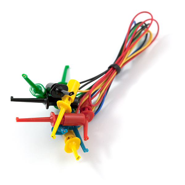
IC Hook Test Leads
CAB-00501 -
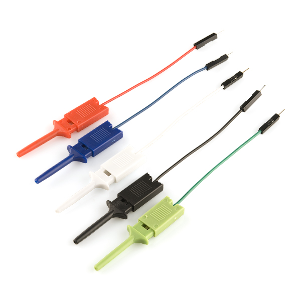
IC Hook with Pigtail
CAB-09741 -
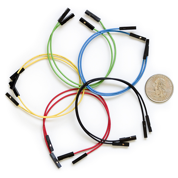
Jumper Wires Premium 6" Mixed Pack of 100
PRT-09194 -
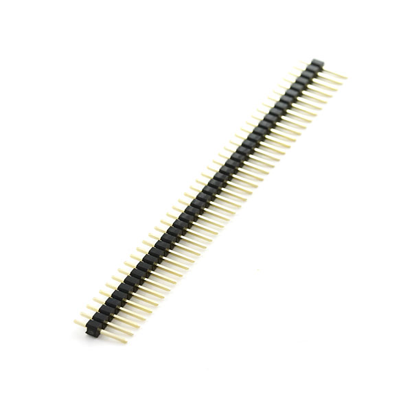
Break Away Headers - Straight
PRT-00116 -
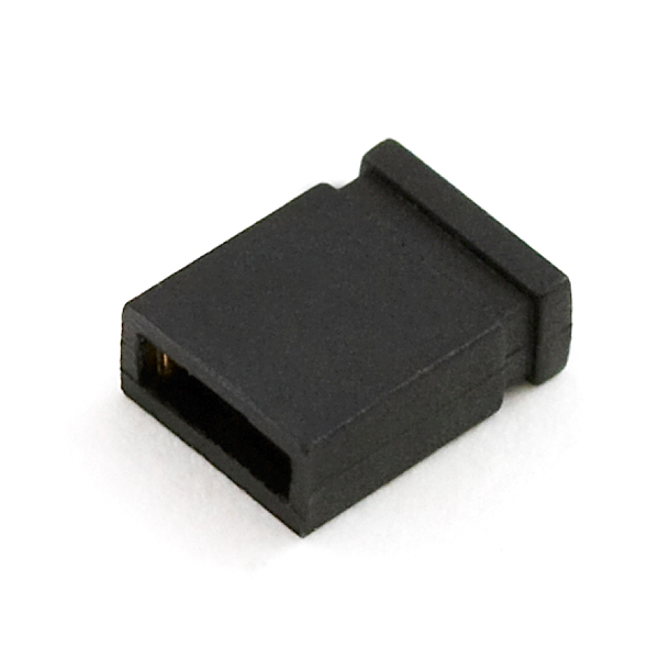
Jumper - 2 Pin
PRT-09044
After users have jumpered the GPIO pins and uploaded the example code, they will need to open the Serial Monitor in the Arduino IDE. Any entries that are sent through the message textbox, should be re-transmitted back into the Serial Monitor by the jumpered GPIO pins.
Users can find this sketch in the File > Examples > 04.Communication > MultiSerial drop-down menu.
MultiSerial.ino
Users can find this sketch in the File > Examples > 04.Communication > SerialPassthrough drop-down menu.
SerialPassthrough.ino
Peripheral Device
GNSS/GPS Module
For GNSS receivers, we recommend that the TinyGPSPlus Arduino library be utilized to parse the NMEA sentences from the module. Once the library is installed in the Arduino IDE, users will find several example sketches listed in the File > Examples > TinyGPSPlus > drop-down menu. We recommend the following examples for getting started with a GNSS receiver:
DeviceExample.inoFullExample.ino
Tip
Below, are a few tips for users to start working with the TinyGPSPlus Arduino library. However, for more details, users should refer to the documentation for the TinyGPSPlus Arduino library.
Define Parameters
When utilizing the examples in the TinyGPSPlus Arduino library, users may need to define and/or modify a few parameters. The baud rate for the GNSS receiver should be configured based upon the information presented in the datasheet.
For the RA6M5 Thing Plus, users have two options for configuring the serial port on the RX and TX GPIO pins:
- In the examples, they can continue to implement the SoftwareSerial library and update the values of
RXandTXGPIO pins in the code - Otherwise, users can remove the SoftwareSerial library implementation; and replace it with
Serial1UART port
-
Baud Rate
Check the datasheet or product manual for the default baud rate of the GPS receiver; if necessary, replace the value in the example:
static const uint32_t GPSBaud = 4800;
static const uint32_t GPSBaud = 115200;
In some cases, the datasheet may be inaccurate or the module's configuration was previously changed. In which case, the most common rates to try are:
4800bps9600bps115200bps
-
Update GPIO Pins
Replace the values for the
RX(D20) andTX(D21) GPIO pins for those on the RA6M5 Thing Plus:static const int RXPin =4, TXPin =3; static const int RXPin = 20, TXPin = 21; -
Utilize
Serial1Port
Remove the implementation of the SoftwareSerial library implementation
#include <SoftwareSerial.h>static const int RXPin = 4, TXPin = 3;SoftwareSerial ss(RXPin, TXPin);Then, replace the SoftwareSerial objects with
Serial1classvoid setup() { Serial.begin(115200);ssSerial1.begin(GPSBaud); void loop() { while (ssSerial1.available() > 0) if (gps.encode(ssSerial1.read())) displayInfo();
Hardware Assembly
Connecting a GNSS receiver to a microcontroller is relatively straight forward. Users must provide power to the module through the PWR/VCC and GND pins on the board. Additionally, the TX pin from the GNSS receiver, should be connected to the RX pin of the microcontroller. This will allow the module to transmit the NMEA sentences to the microcontroller.
| Thing Plus | GPS Module |
|---|---|
3V3 |
VCC or PWR |
GND |
GND |
RX (D21) |
TX |
TX (D20) |
--- |
Satellite Fix
As with all GNSS receivers, the module's antenna must have a clear view of the sky (it can't operate inside a building) to receive signal from the GNSS constellation. In addition, the GNSS receiver must acquire a fix on its position, before it starts transmitting complete NMEA sentences (with all the data).
Optional Hardware
-
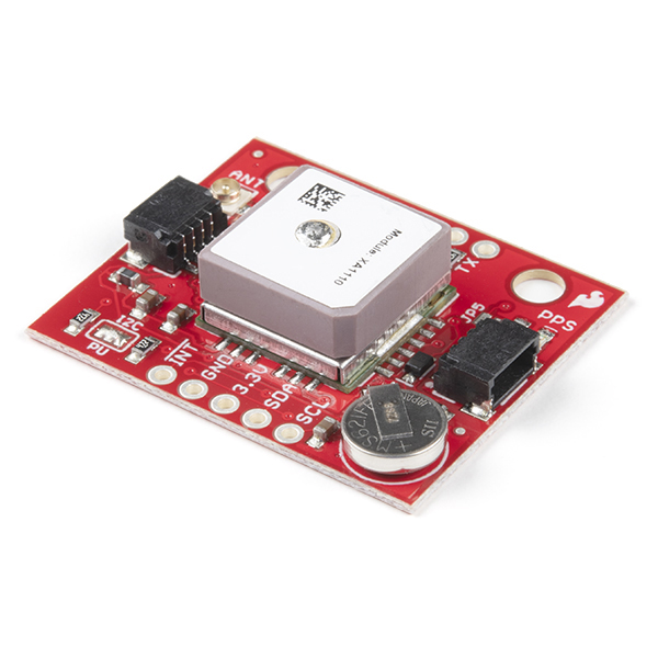
SparkFun GPS Breakout - XA1110 (Qwiic)
GPS-14414 -
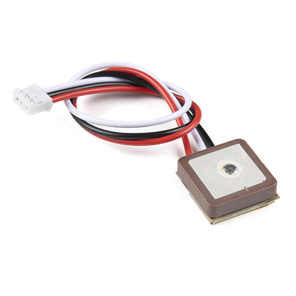
GPS Module - GP1818MK (56 Channel)
GPS-19166 -
IC Hook with Pigtail
CAB-09741 -
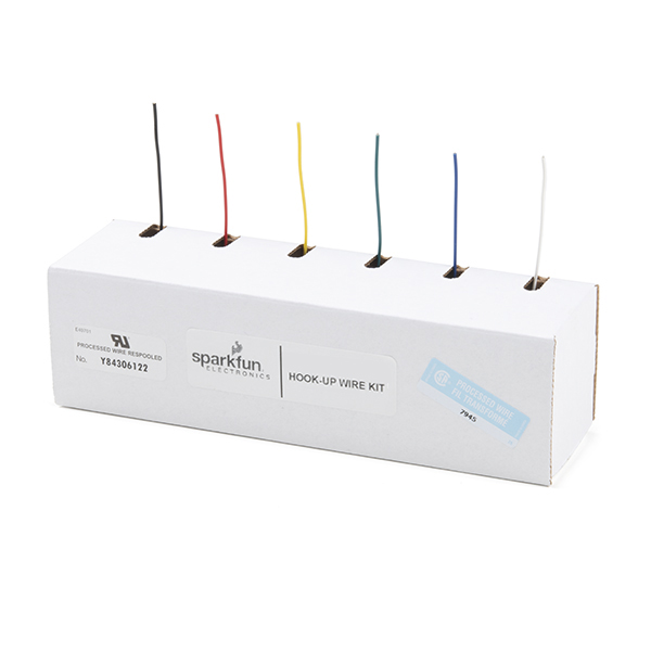
Hook-Up Wire - Assortment (Stranded, 22 AWG)
PRT-11375 -

Solder Lead Free - 100-gram Spool
TOL-09325 -
PINECIL Soldering Iron Kit
KIT-24063
After users have connected their GNSSS module and uploaded the example code, they will need to open the Serial Monitor in the Arduino IDE to view the data. Users should begin to see the data parsed by the TinyGPSPlus Arduino library, from the NMEA sentences transmitted from the GNSS receiver.
Users can find this sketch in the File > Examples > TinyGPSPlus > DeviceExample drop-down menu.
DeviceExample.ino
#include <TinyGPSPlus.h>
#include <SoftwareSerial.h>
/*
   This sample sketch demonstrates the normal use of a TinyGPSPlus (TinyGPSPlus) object.
   It requires the use of SoftwareSerial, and assumes that you have a
   4800-baud serial GPS device hooked up on pins 4(rx) and 3(tx).
*/
static const int RXPin = 4, TXPin = 3;
static const uint32_t GPSBaud = 4800;

// The TinyGPSPlus object
TinyGPSPlus gps;

// The serial connection to the GPS device
SoftwareSerial ss(RXPin, TXPin);

void setup()
{
  Serial.begin(115200);
  ss.begin(GPSBaud);

  Serial.println(F("DeviceExample.ino"));
  Serial.println(F("A simple demonstration of TinyGPSPlus with an attached GPS module"));
  Serial.print(F("Testing TinyGPSPlus library v. ")); Serial.println(TinyGPSPlus::libraryVersion());
  Serial.println(F("by Mikal Hart"));
  Serial.println();
}

void loop()
{
  // This sketch displays information every time a new sentence is correctly encoded.
  while (ss.available() > 0)
    if (gps.encode(ss.read()))
      displayInfo();

  if (millis() > 5000 && gps.charsProcessed() < 10)
  {
    Serial.println(F("No GPS detected: check wiring."));
    while(true);
  }
}

void displayInfo()
{
  Serial.print(F("Location: "));
  if (gps.location.isValid())
  {
    Serial.print(gps.location.lat(), 6);
    Serial.print(F(","));
    Serial.print(gps.location.lng(), 6);
  }
  else
  {
    Serial.print(F("INVALID"));
  }

  Serial.print(F("  Date/Time: "));
  if (gps.date.isValid())
  {
    Serial.print(gps.date.month());
    Serial.print(F("/"));
    Serial.print(gps.date.day());
    Serial.print(F("/"));
    Serial.print(gps.date.year());
  }
  else
  {
    Serial.print(F("INVALID"));
  }

  Serial.print(F(" "));
  if (gps.time.isValid())
  {
    if (gps.time.hour() < 10) Serial.print(F("0"));
    Serial.print(gps.time.hour());
    Serial.print(F(":"));
    if (gps.time.minute() < 10) Serial.print(F("0"));
    Serial.print(gps.time.minute());
    Serial.print(F(":"));
    if (gps.time.second() < 10) Serial.print(F("0"));
    Serial.print(gps.time.second());
    Serial.print(F("."));
    if (gps.time.centisecond() < 10) Serial.print(F("0"));
    Serial.print(gps.time.centisecond());
  }
  else
  {
    Serial.print(F("INVALID"));
  }

  Serial.println();
}
Users can find this sketch in the File > Examples > TinyGPSPlus* > FullExample drop-down menu.
FullExample.ino
#include <TinyGPSPlus.h>
#include <SoftwareSerial.h>
/*
   This sample code demonstrates the normal use of a TinyGPSPlus (TinyGPSPlus) object.
   It requires the use of SoftwareSerial, and assumes that you have a
   4800-baud serial GPS device hooked up on pins 4(rx) and 3(tx).
*/
static const int RXPin = 4, TXPin = 3;
static const uint32_t GPSBaud = 4800;

// The TinyGPSPlus object
TinyGPSPlus gps;

// The serial connection to the GPS device
SoftwareSerial ss(RXPin, TXPin);

void setup()
{
  Serial.begin(115200);
  ss.begin(GPSBaud);

  Serial.println(F("FullExample.ino"));
  Serial.println(F("An extensive example of many interesting TinyGPSPlus features"));
  Serial.print(F("Testing TinyGPSPlus library v. ")); Serial.println(TinyGPSPlus::libraryVersion());
  Serial.println(F("by Mikal Hart"));
  Serial.println();
  Serial.println(F("Sats HDOP  Latitude   Longitude   Fix  Date       Time     Date Alt    Course Speed Card  Distance Course Card  Chars Sentences Checksum"));
  Serial.println(F("           (deg)      (deg)       Age                      Age  (m)    --- from GPS ----  ---- to London  ----  RX    RX        Fail"));
  Serial.println(F("----------------------------------------------------------------------------------------------------------------------------------------"));
}

void loop()
{
  static const double LONDON_LAT = 51.508131, LONDON_LON = -0.128002;

  printInt(gps.satellites.value(), gps.satellites.isValid(), 5);
  printFloat(gps.hdop.hdop(), gps.hdop.isValid(), 6, 1);
  printFloat(gps.location.lat(), gps.location.isValid(), 11, 6);
  printFloat(gps.location.lng(), gps.location.isValid(), 12, 6);
  printInt(gps.location.age(), gps.location.isValid(), 5);
  printDateTime(gps.date, gps.time);
  printFloat(gps.altitude.meters(), gps.altitude.isValid(), 7, 2);
  printFloat(gps.course.deg(), gps.course.isValid(), 7, 2);
  printFloat(gps.speed.kmph(), gps.speed.isValid(), 6, 2);
  printStr(gps.course.isValid() ? TinyGPSPlus::cardinal(gps.course.deg()) : "*** ", 6);

  unsigned long distanceKmToLondon =
    (unsigned long)TinyGPSPlus::distanceBetween(
      gps.location.lat(),
      gps.location.lng(),
      LONDON_LAT,
      LONDON_LON) / 1000;
  printInt(distanceKmToLondon, gps.location.isValid(), 9);

  double courseToLondon =
    TinyGPSPlus::courseTo(
      gps.location.lat(),
      gps.location.lng(),
      LONDON_LAT,
      LONDON_LON);

  printFloat(courseToLondon, gps.location.isValid(), 7, 2);

  const char *cardinalToLondon = TinyGPSPlus::cardinal(courseToLondon);

  printStr(gps.location.isValid() ? cardinalToLondon : "*** ", 6);

  printInt(gps.charsProcessed(), true, 6);
  printInt(gps.sentencesWithFix(), true, 10);
  printInt(gps.failedChecksum(), true, 9);
  Serial.println();

  smartDelay(1000);

  if (millis() > 5000 && gps.charsProcessed() < 10)
    Serial.println(F("No GPS data received: check wiring"));
}

// This custom version of delay() ensures that the gps object
// is being "fed".
static void smartDelay(unsigned long ms)
{
  unsigned long start = millis();
  do
  {
    while (ss.available())
      gps.encode(ss.read());
  } while (millis() - start < ms);
}

static void printFloat(float val, bool valid, int len, int prec)
{
  if (!valid)
  {
    while (len-- > 1)
      Serial.print('*');
    Serial.print(' ');
  }
  else
  {
    Serial.print(val, prec);
    int vi = abs((int)val);
    int flen = prec + (val < 0.0 ? 2 : 1); // . and -
    flen += vi >= 1000 ? 4 : vi >= 100 ? 3 : vi >= 10 ? 2 : 1;
    for (int i=flen; i<len; ++i)
      Serial.print(' ');
  }
  smartDelay(0);
}

static void printInt(unsigned long val, bool valid, int len)
{
  char sz[32] = "*****************";
  if (valid)
    sprintf(sz, "%ld", val);
  sz[len] = 0;
  for (int i=strlen(sz); i<len; ++i)
    sz[i] = ' ';
  if (len > 0)
    sz[len-1] = ' ';
  Serial.print(sz);
  smartDelay(0);
}

static void printDateTime(TinyGPSDate &d, TinyGPSTime &t)
{
  if (!d.isValid())
  {
    Serial.print(F("********** "));
  }
  else
  {
    char sz[32];
    sprintf(sz, "%02d/%02d/%02d ", d.month(), d.day(), d.year());
    Serial.print(sz);
  }

  if (!t.isValid())
  {
    Serial.print(F("******** "));
  }
  else
  {
    char sz[32];
    sprintf(sz, "%02d:%02d:%02d ", t.hour(), t.minute(), t.second());
    Serial.print(sz);
  }

  printInt(d.age(), d.isValid(), 5);
  smartDelay(0);
}

static void printStr(const char *str, int len)
{
  int slen = strlen(str);
  for (int i=0; i<len; ++i)
    Serial.print(i<slen ? str[i] : ' ');
  smartDelay(0);
}
DA14531MOD
For the DA14531MOD, users can interface with the module through the Serial2 UART port of the RA6M5 Thing Plus. The firmware on the module implements the CodeLess AT command platform. This means, users can easily configure the BLE connectivity of the board with a few AT commands. For more details, please refer to the section with the DA14531MOD examples.