Introduction
-
SparkFun Tristimulus Color Sensor - OPT4048DTSR (Qwiic)
SKU: SEN-22638
The SparkFun Tristimulus Color Sensor - OPT4048DTSR (Qwiic) is built around the OPT4048 High Speed High Precision Tristimulus XYZ Color Sensor from Texas Instruments. It is a 1" x 1" Qwiic enabled board that can support up to 4 devices on a shared I2C bus - each capable of measuring four channels with specific engineered spectral responses.
Purchase from SparkFun -
SparkFun Mini Tristimulus Color Sensor - OPT4048DTSR (Qwiic)
SKU: SEN-22639
The Mini version of the SparkFun Tristimulus Color Sensor - OPT4048DTSR (Qwiic) maintains all the functionality of the 1" x 1" breakout board, but in a smaller footprint.
Purchase from SparkFun
Required Materials
To get started, users will need a few items. Now some users may already have a few of these items, feel free to modify your cart accordingly.


Suggested Reading
If you aren’t familiar with the following concepts, we recommend checking out these tutorials before continuing.

Hardware Overview
Color Sensor - OPT4048
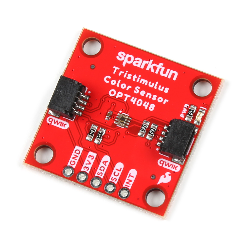
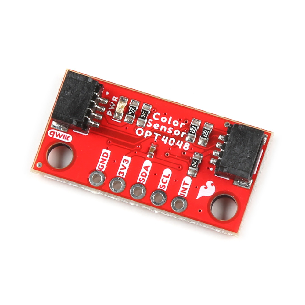
The OPT4048 from Texas Instruments is a single-chip high resolution color sensor, capable of measuring four channels each with specific engineered spectral responses. Three of the four channels closely match the CIE tristimulus spectra with the fourth channel having a wide band spectral response. With measurements from these channels, important characteristics of the lighting environment can be extracted like (i) light intensity (lux), (ii) color in CIE XY, LUV coordinates and (iii) Correlated Color Temperature. For more information, refer to the datasheet.
 The OPT4048 on the Tristimulus Color Sensor. |
 The OPT4048 on the Mini Tristimulus Color Sensor. |


Qwiic Connectors
The boards include two Qwiic connectors on each side of the board.
 The QwiicConnectors on the Tristimulus Color Sensor. |
 The QwiicConnectors on the Mini Tristimulus Color Sensor. |


Power Pins
Ideally, power to these boards will be provided by the Qwiic cables. However, should you wish to provide power separately, the boards have pins broken out to PTH and you can wire up power via these.
Warning
Make sure to pay attention to logic levels - supply voltage range should be between 1.71V - 3.6V.
 The Power Pins on the Tristimulus Color Sensor. |
 The Power Pins on the Mini Tristimulus Color Sensor. |


I2C Pins
If you do not want to use the Qwiic connectors, I2C functionality has been broken out to PTH pins.
 The I2C Pins on the Tristimulus Color Sensor. |
 The I2C Pins on the Mini Tristimulus Color Sensor. |


LEDs
When appropriate power is provided to the board, the power LED lights up on the front of the board.
 The Power LED on the Tristimulus Color Sensor. |
 The Power LED on the Mini Tristimulus Color Sensor. |


Jumpers
Never modified a jumper before?
Check out our Jumper Pads and PCB Traces tutorial for a quick introduction!

Address Selection
The SparkFun Tristimulus Color Sensor - OPT4048DTSR (Qwiic) boards have a default I2C address of 0x44, but by manipulating the address jumpers on the back of the board, you can select 0x45 or 0x46.
 The Address Jumpers on the Tristimulus Color Sensor. |
 The Address Jumpers on the Mini Tristimulus Color Sensor. |


LED Jumpers
If you are concerned about power consumption or you just don't like LEDs, cut the traces here to disconnect the Power LED from, you guessed it, power.
 The LED Jumpers on the Tristimulus Color Sensor. |
 The LED Jumpers on the Mini Tristimulus Color Sensor. |


I2C
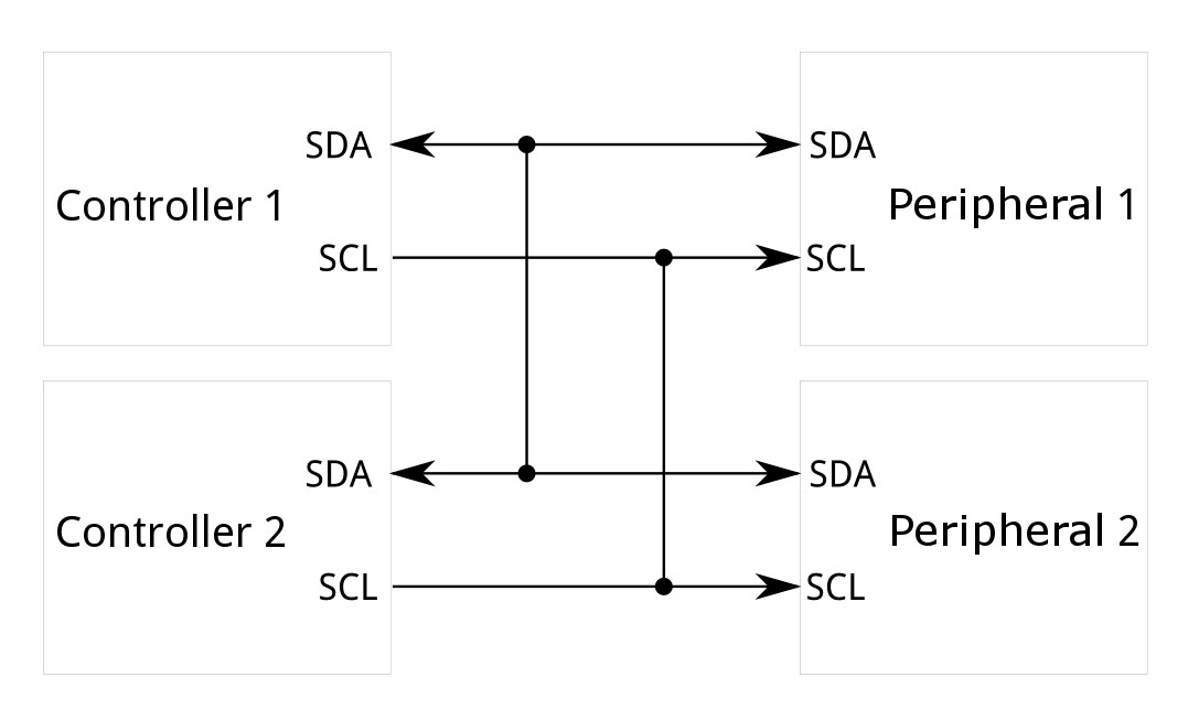
Like our other Qwiic boards, the SparkFun Tristimulus Color Sensor - OPT4048DTSR (Qwiic) boards come equipped with pull-up resistors on the clock and data pins. If you are daisy-chaining multiple Qwiic devices, you will want to cut this jumper; if multiple sensors are connected to the bus with the pull-up resistors enabled, the parallel equivalent resistance will create too strong of a pull-up for the bus to operate correctly. As a general rule of thumb, disable all but one pair of pull-up resistors if multiple devices are connected to the bus. To disable the pull up resistors, use an X-acto knife to cut the joint between the two jumper pads highlighted below.
 The I2C Jumper on the Tristimulus Color Sensor. |
 The I2C Jumper on the Mini Tristimulus Color Sensor. |


Board Dimensions
The SparkFun Tristimulus Color Sensor - OPT4048DTSR (Qwiic) follows the standard 1" x 1" convention of most of our Qwiic breakout boards.

SparkFun Tristimulus Color Sensor - OPT4048DTSR (Qwiic) Board Outline
The SparkFun Mini Tristimulus Color Sensor - OPT4048DTSR (Qwiic) measures 1" x 0.5".

SparkFun Mini Tristimulus Color Sensor - OPT4048DTSR (Qwiic) Board Outline
Need more measurements?
For more information about the board's dimensions, users can download the Eagle files for the 1" x 1" board, or the Eagle files for the Mini board. These files can be opened in Eagle and additional measurements can be made with the dimensions tool.
Eagle - Free Download!
Eagle is a CAD program for electronics that is free to use for hobbyists and students. However, it does require an account registration to utilize the software.
:autodesk-primary:{ .autodesk }
 Dimensions Tool
This video from Autodesk demonstrates how to utilize the dimensions tool in Eagle, to include additional measurements:
Hardware Assembly
Qwiic Assembly
Connecting to the Tristimulus Color breakout is simple. You will just need a microcontroller to process the data when using the OPT4048 and a Qwiic cable. In this case, we used a SparkFun RedBoard Qwiic.

SparkFun Tristimulus Color Sensor Hooked Up to RedBoard Qwiic via a Qwiic Cable

SparkFun Mini Tristimulus Color Sensor Hooked Up to RedBoard Qwiic via a Qwiic Cable
Soldered Assembly
If you prefer to use the plated through holes on the board, you'll need to solder headers to them. Here we've soldered male headers to the breakout board and attached the jumpers as follows:
- Yellow = SCL
- Blue = SDA
- Red = 3.3V
- Black = GND
- Green = Interrupt


 PTH Hookup of Tristimulus Color Sensor |
 PTH Hookup of Mini Tristimulus Color Sensor |
New to Soldering?
If you have never soldered before or need a quick refresher, check out our How to Solder: Through-Hole Soldering guide.

How to Solder: Through-Hole Soldering
Arduino Library
Software Setup
Arduino
Arduino IDE
This example assumes you are using the latest version of the Arduino IDE on your desktop. If this is your first time using Arduino IDE and an library, please review the following tutorials.
USB-to-Serial Drivers
If you've never connected an CH340 device to your computer before, you may need to install drivers for the USB-to-serial converter. Check out our section on "How to Install CH340 Drivers" for help with the installation.
OPT4048
SparkFun has written a library to work with the SparkFun Tristimulus Color Sensors. This library can be used by extension with the SparkFun Tristimulus Color Sensor - OPT4048DTSR (Qwiic). You can obtain this library through the Arduino Library Manager by searching for "OPT4048". Find the one written by SparkFun Electronics and install the latest version. Users who prefer to manually install the library can get it from the GitHub Repository or download the .ZIP by clicking the button below:
Arduino Examples
Example 1: Basic Color Sensing
This first example just does some basic measurements. To find Example 1, go to File > Examples > SparkFun Color Sensor OPT4048 > example1_BasicColorSensing:

Finding Example 1
Alternatively, you can expand the link below and copy and paste the code into a shiny new Arduino sketch:
Example 1: Basic Color Sensing
/*
Example 1 - Basic Color Sensing

This example shows the basic operation of the OPT4048 Color Sensor.
If you're curious about CIE 1931 color space, check out this link:
https://en.wikipedia.org/wiki/CIE_1931_color_space

Written by Elias Santistevan @ SparkFun Electronics, July 2023

Products:
    Qwiic 1x1: https://www.sparkfun.com/products/22638
    Qwiic Mini: https://www.sparkfun.com/products/22639

Repository:
    https://github.com/sparkfun/SparkFun_OPT4048_Arduino_Library

SparkFun code, firmware, and software is released under the MIT
License (http://opensource.org/licenses/MIT).
*/

#include "SparkFun_OPT4048.h"
#include <Wire.h>

SparkFun_OPT4048 myColor;

void setup()
{
    Serial.begin(115200);
    Serial.println("OPT4048 Example 1 Basic Color Sensing.");

    Wire.begin();

    if (!myColor.begin()) {
        Serial.println("OPT4048 not detected- check wiring or that your I2C address is correct!");
        while (1) ;
    }

    myColor.setBasicSetup();

    Serial.println("Ready to go!");
}


void loop()
{
    Serial.print("CIEx: ");
    Serial.print(myColor.getCIEx());
    Serial.print(" CIEy: ");
    Serial.println(myColor.getCIEy());
    // Delay time is set to the conversion time * number of channels
    // You need three channels for color sensing @ 200ms conversion time = 600ms.
    delay(200);
}
Make sure you've selected the correct board and port in the Tools menu and then hit the upload button. Once the code has finished uploading, go ahead and open a Serial Monitor. You should see something similar to the following.

Example 1 Output
The CIEx and CIEy values are going to fall somewhere between 0 and 1. Page 35 of the datasheet gives more detail on this, but generally speaking, you can map the predominant color of the space you're measuring using the following:

CIE XY and CIE UV space plots of color coordinates
For more information on the CIE and CIY values, refer to the CIE 1931 Color Space Wiki Page.
Example 2: Basic Lux Readings
This example measures the lux readings of the surrounding environment. To find Example 2, go to File > Examples > SparkFun Color Sensor OPT4048 > example2_BasicLuxSensing:

Finding Example 2
Alternatively, you can expand the link below and copy and paste the code into a shiny new Arduino sketch:
Example 2: Basic Lux Sensing Arduino Code
/*
Example 2 - Basic Lux Sensing

This example shows the basic operation of the OPT4048 Color Sensor
for sensing light intensity.

Written by Elias Santistevan @ SparkFun Electronics, July 2023

Products:
    Qwiic 1x1: https://www.sparkfun.com/products/22638
    Qwiic Mini: https://www.sparkfun.com/products/22639

Repository:
    https://github.com/sparkfun/SparkFun_OPT4048_Arduino_Library

SparkFun code, firmware, and software is released under the MIT
License (http://opensource.org/licenses/MIT).
*/

#include "SparkFun_OPT4048.h"
#include <Wire.h>

SparkFun_OPT4048 myColor;

void setup()
{
    Serial.begin(115200);
    Serial.println("OPT4048 Example 2 Basic Lux Sensing.");

    Wire.begin();

    if (!myColor.begin()) {
        Serial.println("OPT4048 not detected- check wiring or that your I2C address is correct!");
        while (1) ;
    }

    myColor.setBasicSetup();

    Serial.println("Ready to go!");
}


void loop()
{
    Serial.print("Lux:");
    Serial.print(myColor.getLux());
    // Delay time is set to the conversion time * number of channels
    // You only need one channel for sensing light intensity @ 200ms conversion time = 200ms.
    delay(200);
}
Make sure you've selected the correct board and port in the Tools menu and then hit the upload button. Once the code has finished uploading, go ahead and open a Serial Monitor. You should see something similar to the following.

Example 2 Output
Lux values will be measured anywhere from 2.15 mlux to 144 klux. Measurements here start at my general office lighting, and then I put my finger over the sensor.
Example 3: Basic Color Warmth
This example measures the basic color warmth. To find Example 3, go to File > Examples > SparkFun Color Sensor OPT4048 > example3_BasicColorWarmth:

Finding Example 3
Alternatively, you can expand the link below and copy and paste the code into a shiny new Arduino sketch:
Example 3: Basic Color Warmth Arduino Code
/*
Example 3 - Color Warmth

This example shows how to retrieve the Corelated Color Temperature (CCT) from the OPT4048.
If you need more information on CCT, check out this Wikipedia article:
https://en.wikipedia.org/wiki/Correlated_color_temperature

Written by Elias Santistevan @ SparkFun Electronics, July 2023

Products:
    Qwiic 1x1: https://www.sparkfun.com/products/22638
    Qwiic Mini: https://www.sparkfun.com/products/22639

Repository:
    https://github.com/sparkfun/SparkFun_OPT4048_Arduino_Library

SparkFun code, firmware, and software is released under the MIT
License (http://opensource.org/licenses/MIT).
*/

#include "SparkFun_OPT4048.h"
#include <Wire.h>

SparkFun_OPT4048 myColor;

void setup()
{
    Serial.begin(115200);
    Serial.println("OPT4048 Example 3 Basic Color Warmth.");

    Wire.begin();

    if (!myColor.begin()) {
        Serial.println("OPT4048 not detected- check wiring or that your I2C address is correct!");
        while (1) ;
    }

    myColor.setBasicSetup();

    Serial.println("Ready to go!");
}


void loop()
{
    Serial.print("Color Warmth: ");
    Serial.print(myColor.getCCT());
    Serial.println("K");
    // Delay time is set to the conversion time * number of channels
    // You need three channels for color sensing @ 200ms conversion time = 600ms.
    delay(600);
}
Make sure you've selected the correct board and port in the Tools menu and then hit the upload button. Once the code has finished uploading, go ahead and open a Serial Monitor. You should see something similar to the following.

Example 3 Output
Color warmth addresses the perceived "feel" of the color. Color temperatures over 5000 K are called "cool colors" (bluish), while lower color temperatures (2700–3000 K) are called "warm colors" (yellowish).

For more information on color temperature values, refer to the Color temperature Wiki Page.
Example 4: Color Settings
The color settings example lists the conversion times for each channel. In a nutshell, the longer the conversion time, the more accurate the read values. To find Example 4, go to File > Examples > SparkFun Color Sensor OPT4048 > example4_ColorSettings:

Finding Example 4
Alternatively, you can expand the link below and copy and paste the code into a shiny new Arduino sketch:
Example 4: Basic Color Senttings
/*
Example 4 - This example shows some of the examples.

This example shows the various settings for the OPT4048 and how to set and read them.

Written by Elias Santistevan @ SparkFun Electronics, July 2023

Products:
    Qwiic 1x1: https://www.sparkfun.com/products/22638
    Qwiic Mini: https://www.sparkfun.com/products/22639

Repository:
    https://github.com/sparkfun/SparkFun_OPT4048_Arduino_Library

SparkFun code, firmware, and software is released under the MIT
License (http://opensource.org/licenses/MIT).
*/

#include "SparkFun_OPT4048.h"
#include <Wire.h>

SparkFun_OPT4048 myColor;

void setup()
{
    Serial.begin(115200);
    Serial.println("OPT4048 Example 4 OPT4048 Advanced Settings");

    Wire.begin();

    if (!myColor.begin()) {
        Serial.println("OPT4048 not detected- check wiring or that your I2C address is correct!");
        while (1) ;
    }


    /////////////////////////////////////////////General Settings
    /*
     RANGE_2KLUX2,
     RANGE_4KLUX5,
     RANGE_9LUX,
     RANGE_18LUX,
     RANGE_36LUX,
     RANGE_72LUX,
     RANGE_144LUX,
     RANGE_AUTO
     A higher color range will result in a lower resolution.
     The RANGE_AUTO option will automatically select the best
     range for the current light conditions.
    */
    myColor.setRange(RANGE_2KLUX2);
    Serial.print("Range set to: ");
    Serial.println(myColor.getRange());
    //

    /*
     CONVERSION_TIME_600US,
     CONVERSION_TIME_1MS,
     CONVERSION_TIME_1MS8,
     CONVERSION_TIME_3MS4,
     CONVERSION_TIME_6MS5,
     CONVERSION_TIME_12MS7,
     CONVERSION_TIME_25MS,
     CONVERSION_TIME_50MS,
     CONVERSION_TIME_100MS,
     CONVERSION_TIME_200MS,
     CONVERSION_TIME_400MS,
     CONVERSION_TIME_800MS
     A higher conversion time will result in more precise readings.
     For color sensing, having the highest converstion time is suggested.
    */
    myColor.setConversionTime(CONVERSION_TIME_800MS);
    Serial.print("Conversion time set to:");
    Serial.println(myColor.getConversionTime());

    /*
     OPERATION_MODE_POWER_DOWN,
     OPERATION_MODE_AUTO_ONE_SHOT,
     OPERATION_MODE_ONE_SHOT,
     OPERATION_MODE_CONTINUOUS
    */
    myColor.setOperationMode(OPERATION_MODE_CONTINUOUS);
    Serial.print("Conversion time set to:");
    Serial.println(myColor.getOperationMode());


   // The Quick wake setting changes the behavior of the chip while in power down mode:
   // Not all of the circuitry will be powered down.
   // myColor.setQwake();
    Serial.println("Ready to go!");
}


void loop()
{
    Serial.print("CIEx: ");
    Serial.println(myColor.getCIEx());
    Serial.print("CIEy: ");
    Serial.println(myColor.getCIEy());
    Serial.print("CCT: ");
    Serial.println(myColor.getCCT());
    // Delay time is set to the conversion time * number of channels
    // You need three channels for color sensing @ 800ms conversion time = 3200ms.
    delay(3200);
}
Make sure you've selected the correct board and port in the Tools menu and then hit the upload button. Once the code has finished uploading, go ahead and open a Serial Monitor. You should see something similar to the following.

Example 4 Output
Example 5: Interrupt
The OPT4048 Color Sensor can be triggered by an interrupt if desired. Example 5 shows a simple setup case. To find Example 5, go to File > Examples > SparkFun Color Sensor OPT4048 > example5_Interrupt:

Finding Example 5
Alternatively, you can expand the link below and copy and paste the code into a shiny new Arduino sketch:
Example 5: Interrupt
/*
Example 5 - Interrupts

This example shows the various interrupt settings and their uses.

Written by Elias Santistevan @ SparkFun Electronics, July 2023

Products:
    Qwiic 1x1: https://www.sparkfun.com/products/22638
    Qwiic Mini: https://www.sparkfun.com/products/22639

Repository:
    https://github.com/sparkfun/SparkFun_OPT4048_Arduino_Library

SparkFun code, firmware, and software is released under the MIT
License (http://opensource.org/licenses/MIT).
*/

#include "SparkFun_OPT4048.h"
#include <Wire.h>

SparkFun_OPT4048 myColor;

int interruptPin = 3;

void setup()
{
    Serial.begin(115200);
    Serial.println("OPT4048 Example 5 - Interrupts.");

    pinMode(interruptPin, INPUT);

    Wire.begin();

    if (!myColor.begin()) {
        Serial.println("OPT4048 not detected- check wiring or that your I2C address is correct!");
        while (1) ;
    }

    // See Color Settings Example for functions for setting
    // converstion time, range, and mode.
    myColor.setBasicSetup();

    // Basic usage: if interrupt is set to latched mode
    //myColor.setIntLatch();
    myColor.setIntMechanism(INT_DR_ALL_CHANNELS);

    // Select the channel that will fire the interrupt
    // Lux values are generated in Channel One.
    //myColor.setThresholdChannel(THRESH_CHANNEL_CH1);

    // Change the interrupt direction to active HIGH.
    //myColor.setIntActiveHigh();

    // Change the interrupt to an INPUT to trigger measurements
    // set operation mode to one shot mode in this case.
    // myColor.setIntInput();

    Serial.println("Ready to go!");
}


void loop()
{
    if(digitalRead(interruptPin) == LOW)
    {
        Serial.print("CIEx: ");
        Serial.println(myColor.getCIEx());
        Serial.print("CIEy: ");
        Serial.println(myColor.getCIEy());
    }
    // Delay time is set to the conversion time * number of channels
    // You need three channels for color sensing @ 200ms conversion time = 600ms.
    delay(200);
}
The hardware setup should look something like this:

Example 5 Setup
The example code sets the interrupt pin as Pin 3, but if you change the code, you'll need to change the hardware setup.
Make sure you've selected the correct board and port in the Tools menu and then hit the upload button. Once the code has finished uploading, go ahead and open a Serial Monitor.

Example 5 Output
The output here sits at "Ready to go" until pin 3 is pulled low, then the output starts to roll by.
Troubleshooting Tips
Resources:
Resources
For more resources related to the SparkFun Tristimulus Color Sensor - OPT4048DTSR (Qwiic) boards, check out the links listed here:
SparkFun Tristimulus Color Sensor - OPT4048DTSR (Qwiic):
- Product Page
- Schematic (PDF)
- Eagle Files (ZIP)
- Board Dimensions (PDF)
SparkFun Mini Tristimulus Color Sensor - OPT4048DTSR (Qwiic):
- Product Page
- Schematic (PDF)
- Eagle Files (ZIP)
- Board Dimensions (PDF)
General: