Introduction
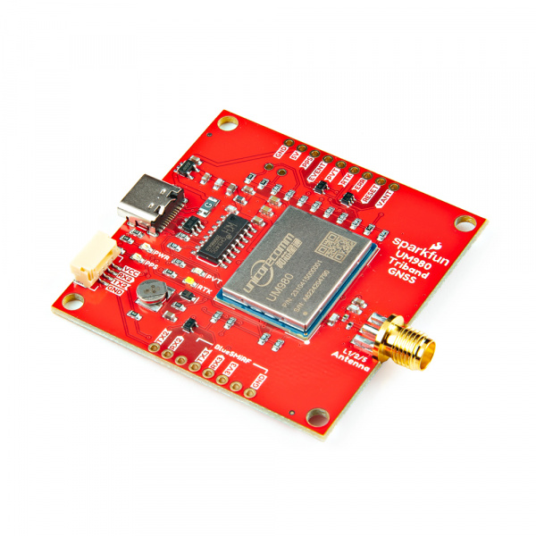
The SparkFun Triband GNSS RTK Breakout features the UM980 GNSS high precision RTK position module from Unicore Communications. The UM980 is a 1408-Channel GNSS Receiver based on the Nebulas IV™ that is able to simultaneously track GPS L1/L2/L5, GLONASS L1/L2, Galileo E1/E5a/E5b/E6, Beidou B1I/B2I/B3I/B1C/B2a/B2b, QZSS L1/L2/L5, and SBAS. With this board, you will be able to know where your (or any object's) X, Y, and Z location is within roughly the width of your fingernail. When an RTK solution is reached, the module can achieve a horizontal accuracy of about 8mm (~0.3 inches) and vertical accuracy of 15mm (~0.59 inches). The UM980 is capable of both rover and base station operations.
In this tutorial, we'll go over the hardware and how to hookup the breakout board. We will also go over the Arduino examples to get started.
Required Materials
To follow along with this tutorial, you will need the following materials. You may not need everything though depending on what you have. Add it to your cart, read through the guide, and adjust the cart as necessary.
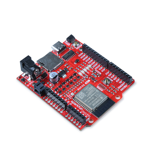
- 1x SparkFun IoT RedBoard - ESP32 Development Board [WRL-19177]
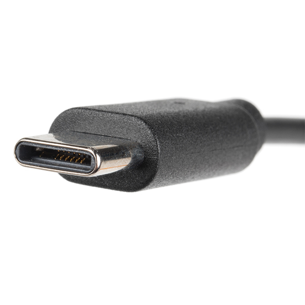
- 1x Reversible USB A to C Cable - 0.8m [CAB-15425]
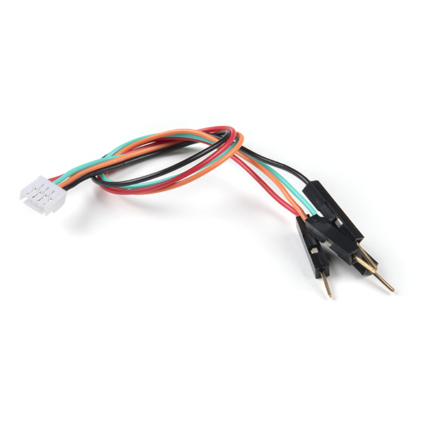
- 1x Breadboard to JST-GHR-04V Cable - 4-Pin x 1.25mm Pitch [CAB-17240]
- 1x SparkFun Triband GNSS RTK Breakout - UM980 [GPS-23286]
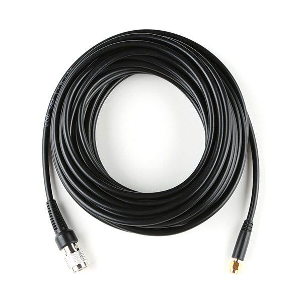
- 1x Reinforced Interface Cable - SMA Male to TNC Male (10m) [CAB-21740]
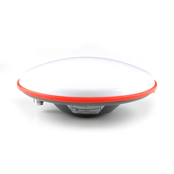
- 1x GNSS Multi-Band L1/L2/L5 Surveying Antenna - TNC (SPK6618H) [GPS-21801]
GNSS Accessories (Optional)
Depending on your setup, you may need the following mounting hardware. Note that the antenna ground plate is needed for tri-band antennas that do not have a ground plane.
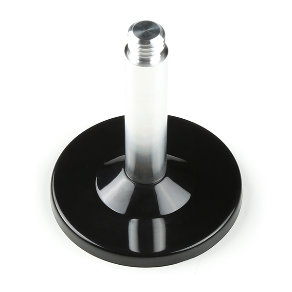
- GNSS Magnetic Mount [PRT-21257]
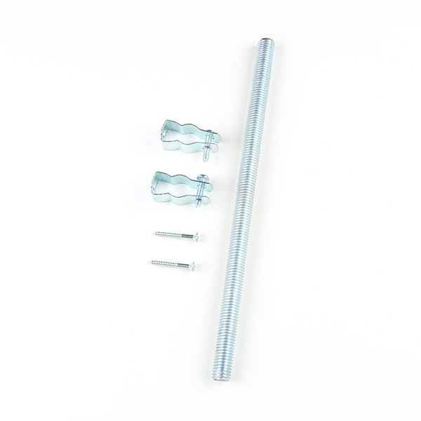
- GNSS Antenna Mounting Hardware Kit [KIT-22197]
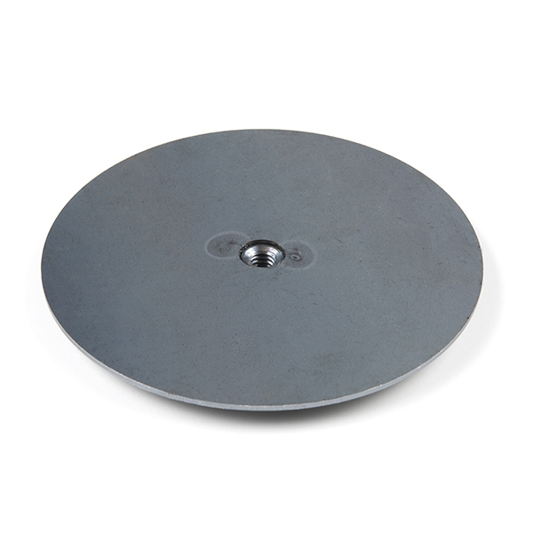
- GPS Antenna Ground Plate [GPS-17519]
Radios (Optional)
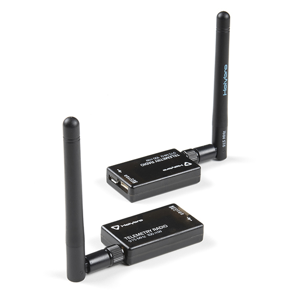
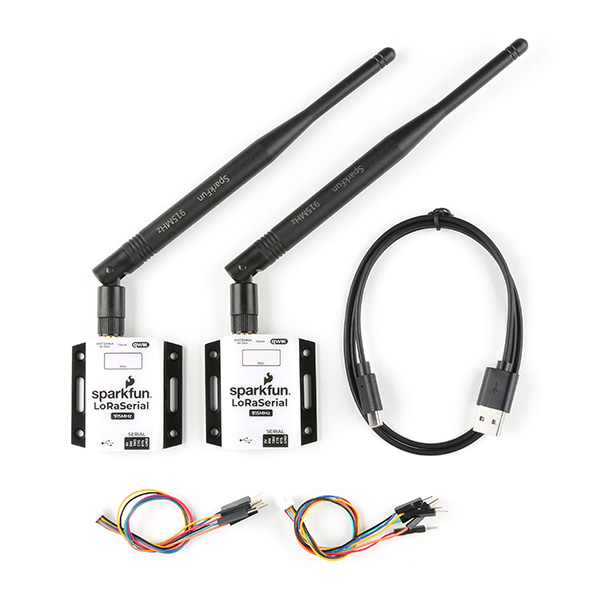
For users that require radios to transmit RTK correction data, you could use the following radios.
- SiK Telemetry Radio V3 - 915MHz, 100mW [WRL-19032]
- SparkFun LoRaSerial Kit - 915MHz (Enclosed) [WRL-20029]
Tools (Optional)
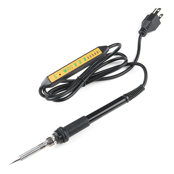
You will need a soldering iron, solder, and general soldering accessories for a secure connection when using the plated through holes.
- Soldering Iron [TOL-14456]
- Solder Lead Free - 15-gram Tube [TOL-9163]
- Flush Cutters - Xcelite [TOL-14782]
- Hook-Up Wire - Assortment (Stranded, 22 AWG) [PRT-11375]
- Wire Stripper - 20-30 AWG Solid (22-32 AWG Stranded) [TOL-22263]

Prototyping Accessories (Optional)
As listed earlier, we recommend using the 4-pin JST-GHR-04V cable to connect directly to the IoT RedBoard - ESP32's female header pins. However, you could also use IC hooks for a temporary connection depending on your setup and what you have available. For those that prefer to the 0.1" spaced PTH, you will want to solder header pins for a secure connection.
- Breadboard - Self-Adhesive (White) [PRT-12002]
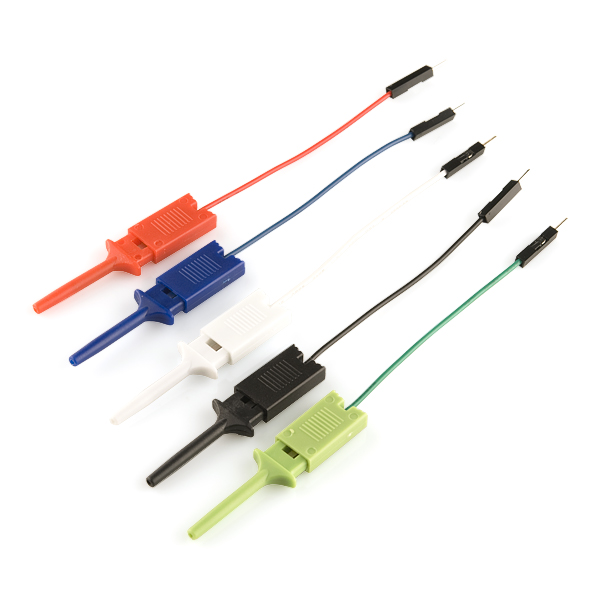
- IC Hook with Pigtail [CAB-09741]
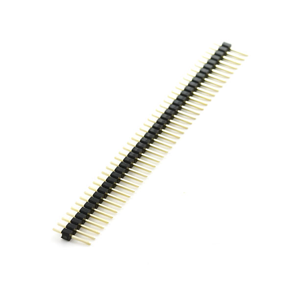
- Break Away Headers - Straight [PRT-00116]
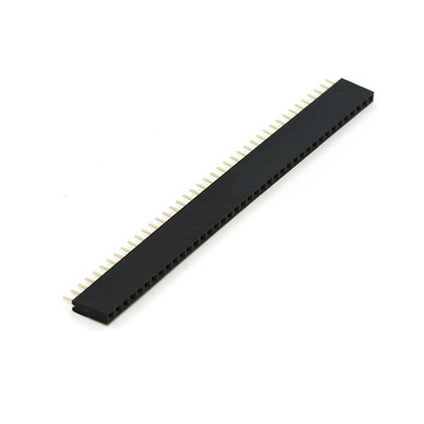
- Female Headers [PRT-00115]
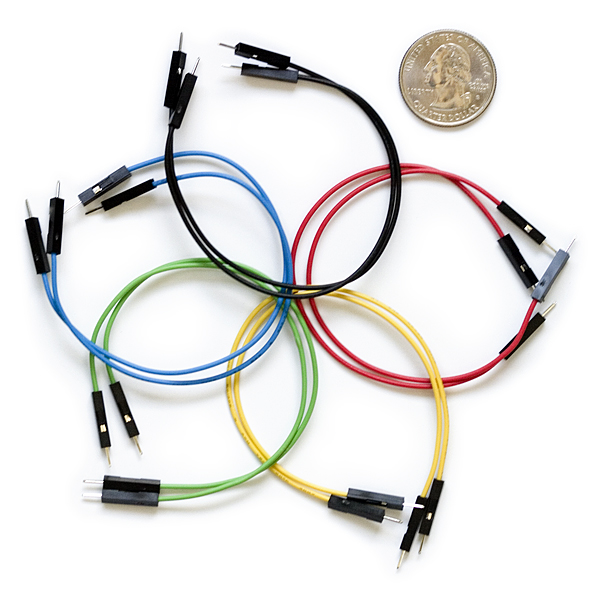
- Jumper Wires Premium 6" M/M Pack of 10 [PRT-08431]
Suggested Reading
If you aren’t familiar with the following concepts, we also recommend checking out a few of these tutorials before continuing.


You may also be interested in the following blog posts on GNSS technologies.
-

GPS vs GNSS
-

What is Correction Data?
-

Real-Time Kinematics Explained
Hardware Overview
In this section, we will highlight the hardware and pins that are broken out on the SparkFun Triband GNSS RTK Breakout - UM980. For more information, check out our Resources and Going Further for the UM980.
 |
 |
| Top View | Bottom View |
UM980 Module
The board breaks out the UM980 which is an all-constellation, all-frequency, high precision RTK positioning module. This module has a low power consumption of about ~480mW.
 |
The UM980 is a 1408-Channel GNSS Receiver based on the Nebulas IV™ that is able to simultaneously track multiple constellation for L1, L2, and L5 bands.
- Concurrent reception of GPS, GLONASS, Galileo, BeiDou, QZSS
- GPS: L1C/A, L1C*, L2P(Y), L2C, L5
- GLONASS: L1, L2
- Galileo: E1, E5a, E5b, E6*
- Beidou: B1I, B2I, B3I, B1C, B2a, B2b*
- QZSS: L1/L2/L5
- SBAS
*: Items marked with * are only supported by specific firmware.
 |
| Image Courtesy of everythingRF |
When a RTK solution is reached, the module can achieve a horizontal accuracy of about 8mm (~0.3 inches) and vertical accuracy of 15mm (~0.59 inches). The UM980 is capable of both rover and base station operations. Below are a few specs taken from the datasheet. For more information, check out the related documents for the UM980 in the Resources.
- Horizontal Accuracy
- Autonomous: 1.5m
- DGPS: 0.4m
- RTK: 0.8cm + 1ppm
- Vertical Accuracy
- Autonomous: 2.5m
- DGPS: 0.8m
- RTK: 1.5cm + 1ppm
- 50Hz Data Update Rate*
- Time-To-First-Fix:
- Cold: 30s
- Warm: 20s
- Hot: 5s
- CoCom Limits
- Max Altitude: 18000m
- Max G: <5G
- Max Velocity: 515m/s
- Velocity Accuracy (RMS): 0.03m/s
- Time Accuracy (RMS): 20ns
*: Items marked with * are only supported by specific firmware.
Power
There are a variety of power and power-related nets broken out to connectors and through hole pads. Power is regulated down to 3.3V with the AP2122K 3.3V/600mA voltage regulator. The logic levels for the UM980 is 3.3V for the I/O pins.
- 5V — Power from the USB C connector's VBUS provides power to the 5V bus. A resettable fuse is connected between the two nets The 5V net is also connected to the edge PTH pin labelled as 5V and the input of the 3.3V voltage regulator. Care must be taken when connecting to this pin to avoid conflicting voltages between the breakout board and anything connect to the 5V pin. Note that if users cut the default trace on VSEL and add solder between the center pad and pad labeled as 5V, the JST locking connector will provide 5V to any device connected on that port as well.
- VCC — The VCC pin on the JST locking connector provides 3.3V by default to any device that is connected to this port. Users can adjust this voltage by cutting the default trace on the VSEL jumper, and adding a solder blob between the center pad and pad labeled as 5V.
- 3V3 — The 3V3 pin under the BlueSMiRF provides 3.3V to the any serial device that is connected. If a serial device that is connecting to this port has its own power supply, make sure to cut the trace on the BT-VCC jumper on the back to avoid conflicting voltages.
- VANT — The voltage antenna (VANT) pin connects to the VANT jumper's EXT pad. This will provide power to an active antenna on the SMA connector if users cut the default trace on the VANT jumper, and add a solder blob between the center pad and pad labeled as EXT.
- GND — Of course, is the common, ground voltage (0V reference) for the system.
 |
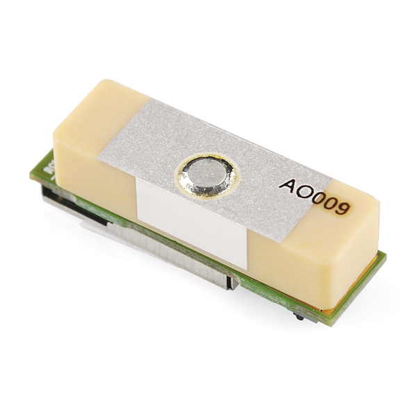
Backup Battery
The small metal disk is a small 3V/1mAh lithium battery. This battery does not provide power to the IC like the 3.3V system does, but to relevant systems inside the IC that allow for a quick reconnection to satellites. The first time to fix (TTFF) is about ~30 seconds. With the backup battery, the warm start is less than 20 seconds and the hot start is less than 5 seconds.
 |
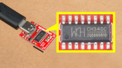
CH340 USB-to-Serial Converter
The top side of the board includes a CH340 USB-to-serial converter connected to the serial UART1 port. The chip can be used to send serial data between the device and computer. You can view the output or configure the device through a serial terminal. When using the UM980 with Unicore's UPrecise Software, you can also initiate firmware updates.
 |
The CH340 driver should automatically install on most operating systems. However, there is a wide range of operating systems out there. You may need to install drivers the first time you connect the chip to your computer's USB port or when there are operating system updates. For more information, check out our How to Install CH340 Drivers Tutorial.
Serial UARTs
Note
Current serial UART is only supported on the UM980 module. I2C, SPI, and CAN have been reserved on the module but are not currently supported.
There are three serial UART ports available on the breakout board. Serial UART1 is connected to the CH340 USB-to-serial converter as stated earlier. Serial UART2 is connected to the 4-pin locking JST connector. Tx and Rx are also broken out as PTHs. We recommend using a compatible cable to connect to the locking JST connector to save time connecting to a microcontroller. Serial UART3 is connected to the PTH pins labeled as BlueSMiRF on the edge of the board.
 |
 |
 |
| UART1 | UART2 | UART3 |
What is a BlueSMiRF?
The BlueSMiRF was a Bluetooth device that was included in SparkFun's catalog. The footprint consists of a 1x6 header for the serial UART and power pins. Note that the arrangement of the header pins is different from USB-to-serial converters (i.e. FTDI Serial Breakout Boards and CH340 Serial Basics Boards).
SMA Connector
The board is populated with one SMA connector for a secure connection. You will need a multiband GNSS antenna capable of receiving L1, L2, and L5 bands to get the most out of the UM980. Note that this is intended for active antennas. We recommend using the GNSS Multi-Band L1/L2/L5 Surveying Antenna - TNC (SPK6618H) as it includes a built-in ground plane and SMA Male to TNC Male interface cable.
 |
Breakout Pins
Besides the power and serial UART pins, the following pins are also broken out on the edge of the breakout board.
- PPS — The PPS output pin provides a pulse per second when there is a satellite lock. When the UM980 losses a satellite lock, the PPS will continue to blink for about 1 minute. Note that output pulse width and polarity can vary depending on the UM980's configuration. Make sure to check the Unicore Reference Commands Manual for more information.
- EVENT — The EVENT input pin and has an adjustable frequency and polarity.
- PVT — The PVT pin is a status pin and active high. This outputs high when positioning and low when not positioning. This is connected to an LED as well and will light up whenever the pin is high.
- RTK — The RTK pin is a status pin and active high. This outputs high for an RTK fixed solution, and low with other positioning status or no positioning. This is connected to an LED as well and will light up whenever the pin is high.
- ERR — The ERROR pin is active high when there is an error or failing self-detection. The pin is low when passing.
- RESET — The RESET pin is active low and resets the UM980. The recommended active time should be no less than 5ms.
- BIF29 — The BIF29 stands for the built-in function that was broken out from the UM980's pin 29. This is connected to a 10kΩ pull-up resistor that was recommended as part of the design as a testing point. Note that this pin cannot connect to ground, power, or a peripheral I/O.
- BIF28 — The BIF28 stands for the built-in function that was broken out from the UM980's pin 28. This is connected to a 10kΩ pull-up resistor that was recommended as part of the design as a testing point. Note that this pin cannot connect to ground, power, or a peripheral I/O.
 |
 |
| Top View of Breakout Pins | Bottom View of Breakout Pins |
LEDs
The board includes the following status LEDs as indicated in the image below.
- PWR — The power LED is connected to 3.3V and lights up with there is power on the board. Users can disable this LED by cutting the trace connecting the PWR jumper.
- PVT — The PVT LED is connected to the PVT pin. This lights up when positioning. Users can disable this LED by cutting the trace connecting the PVT jumper.
- PPS — By default, the PPS LED will blink when there is a satellite lock. When the UM980 losses a satellite lock, the PPS will continue to blink for about 1 minute. Note that output can vary depending on the UM980's configuration. Make sure to check the Unicore Reference Commands Manual for more information. Users can disable this LED by cutting the trace connecting the PPS jumper.
- RTK — The RTK LED lights up when there is an RTK fixed solution. Users can disable this LED by cutting the trace connecting the RTK jumper.
 |
Jumpers
Note
If this is your first time working with jumpers, check out the How to Work with Jumper Pads and PCB Traces tutorial for more information.
There are a few jumper pads available on the bottom of the board.
- SHLD — This jumper connects the USB Type C connector's shield pin to GND. Cut this to isolate the USB Type C connector's shield pin. This is for advanced users that want to ground their board to their enclosure instead of the ground plane.
- VSEL — This three way jumper sets voltage to the locking JST connector. By default, this is set to 3.3V. Cutting a trace and adding a solder blob between the center pad and the pad labeled as 5V will set the voltage on the locking JST connector to 5V.
- PWR — By default, this jumper is closed. Cut this trace to disable the power LED that is connected to 3.3V.
- PVT — By default, this jumper is closed. Cut this trace to disable the PVT LED connected to PVT.
- PPS — By default, this jumper is closed. Cut this trace to disable the PPS LED connected to PPS.
- RTK — By default, this jumper is closed. Cut this trace to disable the RTK LED connected to RTK.
- BT-VCC — By default, this jumper is closed and connected to 3.3V. If a serial device that is connecting to this port has its own power supply, cut this trace to avoid conflicting voltages.
- VANT — This three way jumper sets the voltage source for the active antenna. By default, this is connected to the INT and uses voltage provided from the board (specifically the UM980's VCC_RF pin). Cut this trace and add a solder blob between the center pad and the pad labeled as EXT to provide external power to your active antenna. Make sure to also provide power on the VANT PTH and connect GND from the external power supply the rest of the GND plane.
 |
3D Model
A 3D model of the board and components were exported to a STEP file using KiCad.
Board Dimensions
The board is 2.0" x 2.0" (50.8mm x 50.8mm). There are 4x mounting holes by each corner of the board.
 |
Hardware Hookup
In this section, we'll go over how to connect the Triband GNSS Antenna, GNSS RTK Breakout - UM980, and IoT RedBoard - ESP32 for embedded systems. Of course, you can also connect the UM980 directly to your computer without the need for a microcontroller if you decide to use the UPrecise Software as well.
L1/L2/L5 Multiband GNSS Antenna
Connect a compatible multi-band antenna that is capable of receiving L1, L2, and L5 bands. In this case, we used the "GNSS Multi-Band L1/L2/L5 Surveying Antenna - TNC (SPK6618H)." This also has a ground plane embedded in the antenna. Insert the TNC side of the interface cable into the antenna's TNC connector. Secure the connection by tightening the screw until it is finger-tight. Then insert the SMA side of the interface cable into the Triband GNSS RTK Breakout's SMA connector. Secure the connection by using the SMA's hex nut until it is finger-tight.
 |
Note
For users that are using a different multiband antenna, you may need to include a antenna ground plate to get the most of the multi-band antenna.
Note
Not all multiband antennas are made the same! Make sure that you are connecting a multi-band antenna that is capable of receiving L1/L2/L5 signals when using the Triband GNSS RTK Breakout - UM980.
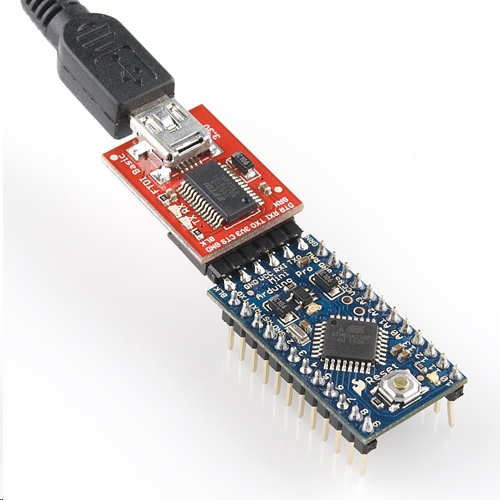
Microcontroller
Note
The Arduino Library was written and tested with the ESP32 processor. We recommend using the IoT RedBoard - ESP32 for the scope of this tutorial.
For users using the breakout board in embedded applications, you will need to plug in the JST-GHR-04V Cable to the Triband GNSS RTK Breakout - UM980. You will then need to connect the other end to a microcontroller to process the data. In this case, we used the IoT RedBoard - ESP32.
| IoT RedBoard - ESP32 | Triband GNSS RTK Breakout - UM980 |
|---|---|
| 3V3 | 3.3V |
| UART1_TX (D4) | RX2 |
| UART1_RX (D13) | TX2 |
| GND | GND |
 |
USB to Microcontroller
To power and program the IoT RedBoard - ESP32, users will just need to insert the Type C side of the cable to the development board. The other end will connect to a computer's USB port.
 |
USB to Triband GNSS RTK Breakout - UM980
For users that simply want to connect to the board via USB, you will insert a USB C cable into the USB connector. Then connect the other end to your computer USB port.
 |
Connecting via PTH
For temporary connections to the PTHs, you could use IC hooks to test out the pins. However, you'll need to solder headers or wires of your choice to the board for a secure connection. You can choose between a combination of header pins and jumper wires, or stripping wire and soldering the wire directly to the board.

Installing the Arduino Library
Arduino
This example assumes you are using the latest version of the Arduino IDE on your desktop. If this is your first time using the Arduino IDE, library, or board add-on, please review the following tutorials.
SparkFun has written a library to work with the Unicore UM980 module. You can obtain this library through the Arduino Library Manager by searching for "SparkFun Unicore GNSS". Find the one written by SparkFun Electronics and install the latest version. Users who prefer to manually install the library can get it from the GitHub Repository or download the .ZIP by clicking the button below:
Arduino Examples
Now that we have our library and board add-on installed, we can get started experimenting with the breakout board. For the scope of this tutorial, we will go over the examples from the Arduino Library. From there, we will be able to build our own custom code to integrate the development board into a project.
Example 1: Position, Velocity, and Time
In this example, we will query a UM980's UART2 port for its position, velocity, and time data.
From the menu, select the following: File > Examples > SparkFun UM980 Triband RTK GNSS Arduino Library > Example1_PositionVelocityTime . If you have not already, select your Board (in this case the SparkFun ESP32 IoT RedBoard), and associated COM port. Then hit the upload button. After uploading the code, open the Serial Monitor or terminal emulator of your choice with a baud rate set to 115200.
Give it a moment to check the satellites in view. You will be able to see your position, velocity, date, time, and the number of satellites in view.
 |
Example 2: Direct Connect
In this example, characters coming from the UM980's UART2 port are echoed and send characters to the UM980. This allows a user to directly enter command strings into the UM980 while still connected to the Arduino. This is good for viewing the raw output from a given command.
From the menu, select the following: File > Examples > SparkFun UM980 Triband RTK GNSS Arduino Library > Example2_DirectConnect . If you have not already, select your Board (in this case the SparkFun ESP32 IoT RedBoard), and associated COM port. Then hit the upload button. After uploading the code, open the Serial Monitor or terminal emulator of your choice with a baud rate set to 115200. For this example, make sure to have both NL & *CR turned on.
Type CONFIG and send the command through the serial terminal. You should receive a response with the current UM980 configuration. Make sure to check out the UM980's Reference Commands Manual linked in the Resources for more commands.
 |
Example 3: ECEF and Stats
This example will query the UM980's UART2 port for the signal quality and fix type.
From the menu, select the following: File > Examples > SparkFun UM980 Triband RTK GNSS Arduino Library > Example3_ECEFandStats . If you have not already, select your Board (in this case the SparkFun ESP32 IoT RedBoard), and associated COM port. Then hit the upload button. After uploading the code, open the Serial Monitor or terminal emulator of your choice with a baud rate set to 115200.
The output will be similar to example 1 with additional information.
 |
Example 4: Enable NMEA at 5Hz
This example shows how to enable various NMEA sentences at different rates on different ports at 5Hz.
From the menu, select the following: File > Examples > SparkFun UM980 Triband RTK GNSS Arduino Library > Example4_EnableNMEA_5Hz . If you have not already, select your Board (in this case the SparkFun ESP32 IoT RedBoard), and associated COM port. Then hit the upload button. After uploading the code, open the Serial Monitor or terminal emulator of your choice with a baud rate set to 115200.
The output will begin outputting NEMA sentences.
 |
Example 5: Enable RTCM
This example shows how to configure the UM980 into base mode using specified coordinates.
From the menu, select the following: File > Examples > SparkFun UM980 Triband RTK GNSS Arduino Library > Example5_EnableRTCM . If you have not already, select your Board (in this case the SparkFun ESP32 IoT RedBoard), and associated COM port. Then hit the upload button. After uploading the code, open the Serial Monitor or terminal emulator of your choice with a baud rate set to 115200.
Once open, the example will begin outputting the RTCM data. The Serial Terminal will output random characters due to the RTCM being in binary. This data will be interpreted by other high precision RTK GNSS modules.
 |
Example 6: Average Base
This example shows how to put the UM980 into a Base mode configuration using the average of positional fixes obtained over a 60 second period. We also turn on RTCM messages.
From the menu, select the following: File > Examples > SparkFun UM980 Triband RTK GNSS Arduino Library > Example6_AverageBase . If you have not already, select your Board (in this case the SparkFun ESP32 IoT RedBoard), and associated COM port. Then hit the upload button. After uploading the code, open the Serial Monitor or terminal emulator of your choice with a baud rate set to 115200.
Once open, the example will begin outputting certain NMEA sentences and RTCM messages.
 |
Example 7: Fixed Base
This example shows how to put the UM980 into a Base mode configuration using specified coordinates.
From the menu, select the following: File > Examples > SparkFun UM980 Triband RTK GNSS Arduino Library > Example7_FixedBase . If you have not already, select your Board (in this case the SparkFun ESP32 IoT RedBoard), and associated COM port. Then hit the upload button. After uploading the code, open the Serial Monitor or terminal emulator of your choice with a baud rate set to 115200.
Once open, the example will begin outputting certain NMEA sentences and RTCM messages.
 |
Example 8: Set Constellations
This example enables/disables various constellations to be included in position calculations for GPS, GLO, BDS, GAL, and QZSS.
From the menu, select the following: File > Examples > SparkFun UM980 Triband RTK GNSS Arduino Library > Example8_SetConstellations . If you have not already, select your Board (in this case the SparkFun ESP32 IoT RedBoard), and associated COM port. Then hit the upload button. After uploading the code, open the Serial Monitor or terminal emulator of your choice with a baud rate set to 115200.
Once open, the output will respond with a message indicating if the GPS was enabled and the configuration is complete.
 |
Example 9: Signal Elevation
This example shows how set the Elevation Angle and minimum CN0 value required from a satellite to be included in the position calculation.
From the menu, select the following: File > Examples > SparkFun UM980 Triband RTK GNSS Arduino Library > Example9_SignalEleveation . If you have not already, select your Board (in this case the SparkFun ESP32 IoT RedBoard), and associated COM port. Then hit the upload button. After uploading the code, open the Serial Monitor or terminal emulator of your choice with a baud rate set to 115200.
Once open, the output will notify you when the UM980 is configured.
 |
Example 10: Set Rover Mode
This example shows how set the station mode to Survey, UAV, or Automotive.
From the menu, select the following: File > Examples > SparkFun UM980 Triband RTK GNSS Arduino Library > Example10_SetRoverMode. If you have not already, select your Board (in this case the SparkFun ESP32 IoT RedBoard), and associated COM port. Then hit the upload button. After uploading the code, open the Serial Monitor or terminal emulator of your choice with a baud rate set to 115200.
Once open, the output will notify you when the UM980 is configured. If you need to configure the device for a different mode, you will just need to use a single line comment (//) to adjust the code.
|
Example 11: USB NMEA
This sketch turns on all the major NMEA sentences at 2Hz and prints the incoming serial out to the Serial port. This is useful for viewing the GNSS data in a program like u-center (u-blox's software) or UPrecise (Unicore's software).
From the menu, select the following: File > Examples > SparkFun UM980 Triband RTK GNSS Arduino Library > Example11_UsbNMEA . If you have not already, select your Board (in this case the SparkFun ESP32 IoT RedBoard), and associated COM port. Then hit the upload button. After uploading the code, open the Serial Monitor or terminal emulator of your choice with a baud rate set to 115200.
Once open, the output will notify you when the UM980 is configured.
 |
Disconnect the UM980 from the IoT RedBoard - ESP32. Then disconnect the USB cable from the IoT RedBoard - ESP32. Connect the USB cable between the UM980 and your computer. Open a terminal emulator set at 115200 baud. Once connected, you should begin seeing NMEA sentences through the USB port.
 |
Of course, you can also view the data through a GUI such as the u-center (u-blox's software) or UPrecise (Unicore's software) as well.
Example 12: Factory Reset
This example shows how set the UM980 back to factory defaults.
From the menu, select the following: File > Examples > SparkFun UM980 Triband RTK GNSS Arduino Library > Example12_FactoryReset . If you have not already, select your Board (in this case the SparkFun ESP32 IoT RedBoard), and associated COM port. Then hit the upload button. After uploading the code, open the Serial Monitor or terminal emulator of your choice with a baud rate set to 115200.
Once open, the output will notify you when the UM980 is ready to be configured. Send a character through the Serial Monitor to factory reset the UM980. The code will then begin outputting the position, velocity, date, time, and satellites as shown in example 1. Give it a moment to check the satellites in view before getting valid data.
 |
Example 13: Send Command
While the SparkFun UM980 Arduino library covers most of the features in the UM980, there may be a special command that is needed but not supported. This sketch shows how to send commands directly to the UM980.
From the menu, select the following: File > Examples > SparkFun UM980 Triband RTK GNSS Arduino Library > Example13_SendCommand* . If you have not already, select your Board (in this case the **SparkFun ESP32 IoT RedBoard), and associated COM port. Then hit the upload button. After uploading the code, open the Serial Monitor or terminal emulator of your choice with a baud rate set to 115200.
Once open, there's not too much in the output. Try adjusting the ASCII command within the myGNSS.sendCommand() to send a different special command. For more information, try looking at the Reference Commands Manual in the Resources.
 |
Example 14: Set PPS
The example shows how to configure the PPS signal's width, frequency, and polarity.
From the menu, select the following: File > Examples > SparkFun UM980 Triband RTK GNSS Arduino Library > Example14_SetPPS . If you have not already, select your Board (in this case the SparkFun ESP32 IoT RedBoard), and associated COM port. Then hit the upload button. After uploading the code, open the Serial Monitor or terminal emulator of your choice with a baud rate set to 115200.
Once open, the output just tells you the rate that the PPS is blinking at. If you look at the PPS LED on the UM980, the LED will blink at the rate that was set.
 |
Example 15: Query Device
This example shows how to send the 'CONFIG' command to get a clear text response that the user can parse to see which settings are set. In this case, we will get the current configuration, version, mode, and mask from the UM980.
From the menu, select the following: File > Examples > SparkFun UM980 Triband RTK GNSS Arduino Library > Example15_QueryDevice . If you have not already, select your Board (in this case the SparkFun ESP32 IoT RedBoard), and associated COM port. Then hit the upload button. After uploading the code, open the Serial Monitor or terminal emulator of your choice with a baud rate set to 115200.
 |
Example 16: Poll for Valid RTCM Messages
The documentation for the UM980 does not explicitly state which RTCM messages are supported but by sending the enable command to the module we can insinuate which are supported. This sketch sends the 'RTCMxxxx' command and looks for an OK.
From the menu, select the following: File > Examples > SparkFun UM980 Triband RTK GNSS Arduino Library > Example15_PollForValidRTCMMessages . If you have not already, select your Board (in this case the SparkFun ESP32 IoT RedBoard), and associated COM port. Then hit the upload button. After uploading the code, open the Serial Monitor or terminal emulator of your choice with a baud rate set to 115200.
Once open, the output will notify you of the RTCM messages that are supported. As of the writing of this tutorial, there are 55 RTCM messages that are supported!
 |
Installing UPrecise
For users interested in a GUI to visualize the data or update firmware, there is the UPrecise Software. You can head over to Unicore's UPrecise Download Page. Or clicking on the button below to download UPrecise.
Note
For the latest software version, you may want to check the Unicore's UPrecise Download Page.
Once downloaded, select the executable and follow the prompts to install the software to your computer. Note that the software is currently only supported on Windows 7/8/10, 64-bit OS.
Selecting a Language
After downloading and installing UPrecise, open the software up! There are two languages that are supported with the software. For the scope of this tutorial, we'll be using the software in English. Click on "CH" button to change the default language from Chinese to English.
 |
For users with UPrecise V2.0, you will be prompted with a new window indicating that you will need reboot the software for the changes to take effect. Select the button on the left to reboot the software.
 |
The language will switch to English similar to the image below.
 |
Connecting the UM980 Breakout Board to a Computer
We will assume that you have a triband multiband antenna connected to the UM980's breakout board and USB cable connected to your computer. Select the COM port that the CH340 enumerated to. There is no need to make a selection in the other two drop down menus by the COM port since the software automatically determines the receiver and baud rate. In this case, it was COM17. You may need to open your device manager to determine which COM port the CH340 enumerated to.
 |
Once connected, try exploring the features available on the software as the UM980 sends data to your COM port. You can also check out the UPrecise user manual for more information on the software:
Firmware Update
Note
The following instructions were taken from the UPrecise User Manual: 2.2.11 Receiver Upgrade. For more information about how to use UPrecise software, make sure to check out the user manual.
Note
At the time of writing, UPrecise Version 2.0 was used. Note that the GUI appearance and features may change upon future releases.
You can update your firmware (they call this a firmware upgrade in the manual) using Unicore's UPrecise software. Make sure to check Unicore's UM980 product page, download center, or contact Unicore Communications for any firmware releases.
We'll assume that you have the firmware downloaded at this point and connected to the UM980. With UPrecise open, click on the menu with the triple bar (≡) near the upper left of the window to expand the menu.
|
The menu should expand with text next to each icon.
 |
Click on the Receiver Upgrade button. The following window should open up.
 |
Click the Select upgrade file button. Head to the folder where you downloaded the firmware and select the file. The extension should be a *pkg file. In this case, there was a copy of the firmware in the GitHub SparkFun UM980 Triband GNSS RTK Breakout Repo named "UM980_R4.10Build11833.pkg". Older firmware versions were moved to the Old Firmware folder.
 |
Select the GNSS receiver that will be receiving the firmware update. In this case it was Receiver1. While we are at it, select either the "Soft reset" or "Hard reset". While updating, the module will need to be reset and this selection will determine the reset method. Let's select the "Soft Reset" and have UPrecise reset the module.
 |
When ready, hit the "Start" button!
 |
Warning
Make sure to pay attention to the progress bar! You'll want to avoid any interruptions while the firmware is updating as this will cause the upgrade to fail.
Note
If you have issues updating the software with the reset method chosen, try exiting the Receiver Upgrade menu by hitting the "x" button. Then disconnect and reconnect the module by selecting the "Connect" button. You will then need to open the Receiver Upgrade window again before hitting the "Start" button.
Once the firmware has been updated, you will notice that the progress bar is at 100% and a message indicating that the firmware upgrade succeeded and finished. You can exit out of the window by clicking on the "x" button.
 |
Verification
Now that we have successfully flashed the firmware, let's verify the version number. In the serial terminal, send the command VERSIONA. The UM980 will respond by providing the firmware version and authorization date. Look for the part of the message after the model number (i.e. "UM980"). This should match the build number from *pkg file name.
 |
Note
Sending the command VERSIONA is one method of verifying the version number on the UM980. You can use the Arduino example code to verify the version number on the UM980 breakout board.
 |
Try viewing the UM980 output through the UPrecise software. Not seeing any satellites in the GUI or output in the serial terminal? Try adjusting the configuration to output every second. From the menu, head to the following to configure the messages: Receiver Configurations > Message configuration. In this case, we selected the following: GGA, GSA, GSV, RMC, GST. Feel free to select more depending on your application.
 |
Scroll down Receiver Configurations window and select Enter button.
 |
You should be able to see messages outputting through the serial terminal and displaying graphically.
 |
Troubleshooting
General Troubleshooting Help
Note
Not working as expected and need help?
If you need technical assistance and more information on a product that is not working as you expected, we recommend heading on over to the SparkFun Technical Assistance page for some initial troubleshooting.
If you don't find what you need there, the SparkFun Forums are a great place to find and ask for help. If this is your first visit, you'll need to create a Forum Account to search product forums and post questions.
Resources
Now that you've successfully got your SparkFun TriBand GNSS RTK- Breakout - UM980 up and running, it's time to incorporate it into your own project! For more information, check out the resources below: