Introduction
Info
This tutorial is an update to the BNO080. If you are looking for the original tutorial for the BNO080, make sure to head to the Qwiic VR IMU (BNO080) Hookup Guide. Note that the BNO080 is EOL. Additionally, this tutorial uses a different Arduino Library.
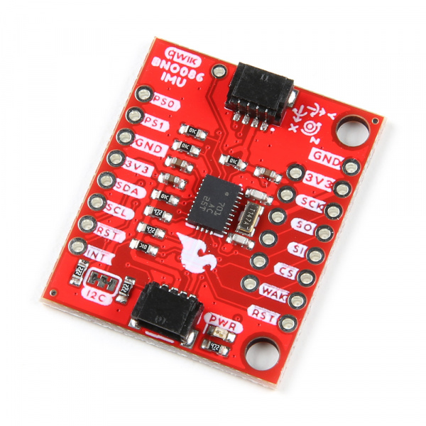
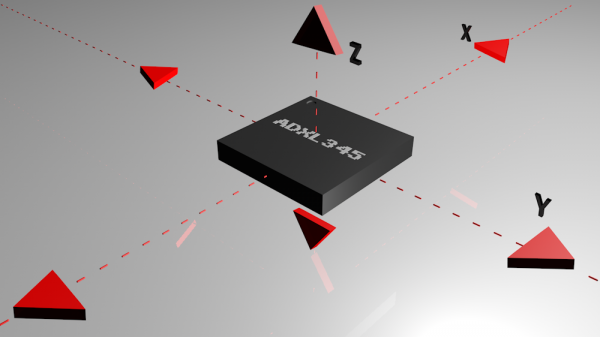
CEVA's BNO086, a combination triple-axis accelerometer/gyro/magnetometer System in Package (SiP), packaged with a 32-bit ARM© Cortex™ M0+. The BNO086 Inertial Measurement Unit (IMU) produces accurate rotation vector headings, excellently suited for VR and other heading applications, with a static rotation error of two degrees or less. The VR IMU is exactly what we’ve been waiting for: all the sensor data is combined and drift-corrected into meaningful, accurate IMU information. It’s perfect for any project that needs to sense orientation or motion. We've taken this IMU and stuck it on a Qwiic enabled breakout board, in order to make interfacing with the tiny, QFN package a bit easier to connect.
In this hookup guide, we'll connect our sensor up to our microcontroller of choice and separately read the rotation vectors (which is what we will mainly want), acceleration vectors, gyro values, and magnetometer vectors. We'll check out how to implement the step counter on the BNO086 in order to use it as a pedometer. We'll also read Q values from the sensor. Knowing what activity you're performing is important so we'll learn how to classify what activity the IMU is performing (i.e. Sitting still, moving, biking, walking, running, etc...) and how confident the IMU is that each activity is being performed. Printing out raw packets will also be examined for debugging purposes. Finally, we'll examine how to configure the sensor on different I2C ports and addresses. A bonus example is provided in Processing to show us how to use quaternion data to orient a cube.
Required Materials
To follow along with this tutorial, you will need the following materials. You may not need everything though depending on what you have. Add it to your cart, read through the guide, and adjust the cart as necessary.
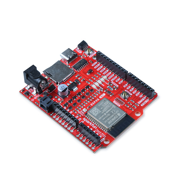
- 1x SparkFun IoT RedBoard - ESP32 Development Board [WRL-19177]
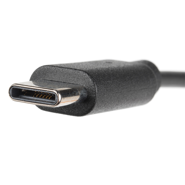
- 1x USB-C cable
- Our USB 2.0 A to C Cable [CAB-15092] will do nicely
- Our USB 3.1 A to C Cable [CAB-14743] is a good choice too
- 1x SparkFun VR IMU Breakout - BNO086 (Qwiic) [SEN-22857]
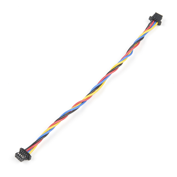
- 1x Qwiic Cable
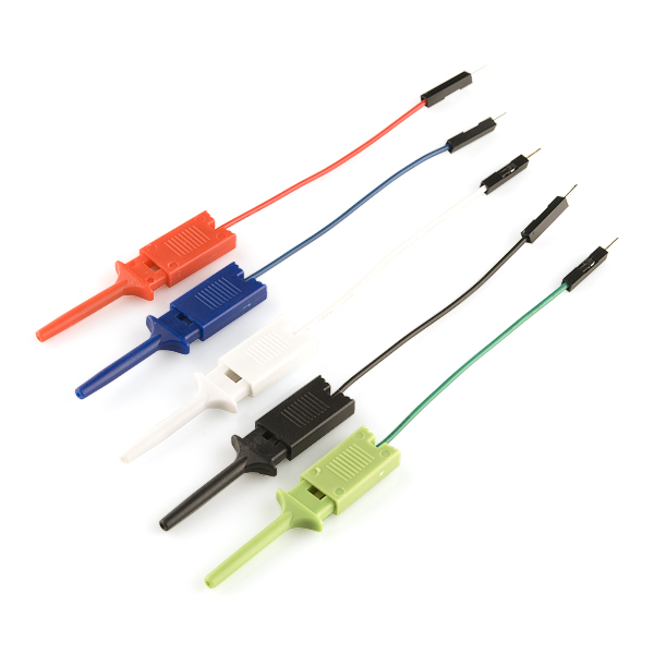
- 2x IC Hooks (optional for advanced configuration)
- The pack of 5x IC Hook with Pigtail [CAB-09741] for a temporary connection
Note
As of Arduino Library v1.0.3, the BNO086 has also been tested to work with a SAMD51 (i.e. SparkFun Thing Plus - SAMD51) as well!
Tools
For a secure connection when connecting to the reset and interrupt pins, you will need to solder two wires between your microcontroller and the breakout board. This requires some assembly and soldering. You may already have a few of these items but if not, the tools and hardware below help with that assembly.
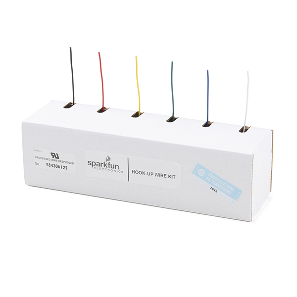
- Hook-Up Wire - Assortment (Stranded, 22 AWG) [PRT-11375]
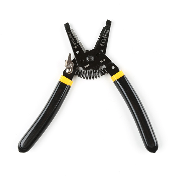
- Wire Stripper - 20-30 AWG Solid (22-32 AWG Stranded) [TOL-22263]
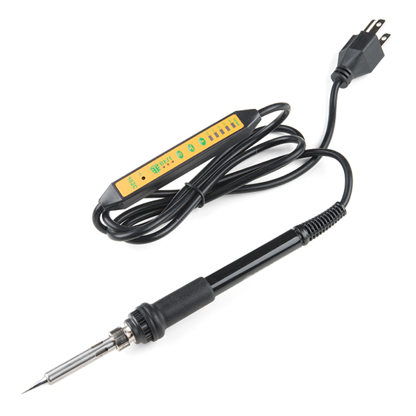
- Soldering Iron [TOL-14456]
- Solder Lead Free - 15-gram Tube [TOL-9163]
Suggested Reading
If you aren't familiar with the Qwiic Connection System, we recommend reading here for an overview.

If you aren’t familiar with the following concepts, we also recommend checking out a few of these tutorials before continuing.


Hardware Overview
Let's look over a few characteristics of the BNO086 sensor so we know a bit more about how it behaves. These characteristics were taken from the datasheet. For more information, make sure to check out the datasheet that is linked in the Resources section.
 |
- I2C (Default): Up to 400kHz
- SPI: Up to 3MHz
- UART: 3Mbps
- Rotation Vector
- Dynamic Error: 3.5°
- Static Error: 2.0°
- Gaming Rotation Vector
- Dynamic Error: 2.5°
- Static Error: 1.5°
- Dynamic Heading Drift: 0.5° / min
- Geomagnetic Rotation Vector
- Dynamic Rotation Error: 4.5°
- Static Rotation Error: 3.0°
- Gravity Angle Error: 1.5°
- Linear Acceleration Accuracy: 0.35m/s2
- Accelerometer Accuracy: 0.3m/s2
- Gyroscope Accuracy: 3.1° / sec
- Magnetometer Accuracy: 1.4µT
Note
Keep in mind the location of the labels on the top and bottom of the board. When rotating the board about the x-axis to view the bottom labels, you will notice that the letters are not right side up. You will need to rotate the board about the y-axis to view the letters.
 |
 |
Power
The operating voltage is between 2.4V-3.6V (note that VDDIO and VDD are tied together on the breakout board). We will assume that users will be using this with the Qwiic Connect System and a 3.3V microcontroller, which is typically 3.3V. We recommend matching the logic levels so that they are the same as the operating voltage (e.g. 3.3V). You can apply 3.3V to the board from the 3V3 pin on either edge of the board, in the middle of the board, or either of the Qwiic connectors. There are also a few GND pins located throughout the board and via the Qwiic connectors.
 |
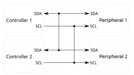
I2C and Qwiic Connectors
The board includes two Qwiic connectors on each side of the board. For users that need to solder directly to the board, the pins are also broken out on the edge PTH. The I2C data and clock lines are also tied to 2.2kΩ pull-up resistors. The BNO086 supports standard fast mode and can communicate over this interface at up to 400kHz.
 |
The default address of the board is set to 0x4B. The alternative address is 0x4A. The protocol selection is also set for I2C by default. These can be adjusted based on the jumpers on the back of the board. For more information, check out the section about the jumpers.
Note
The timing for the BNO086 is finicky on the I2C port and the Arduino Library v1.0 does not currently support more than one BNO086 on the same line. We also do not recommend using a Qwiic Mux between the microcontroller and BNO086 to ensure that the packets are sent reliably.
SPI
A few of the SPI pins have more than one function. We'll focus on the four SPI pins below. The image will also highlight the pins that are tied together.
- SO — This is an output pin for POCI (Peripheral Out, Controller In). The device sends data to the controller on this line. This is also connected to the I2C's SDA and UART's TXO pin.
- SI — This is an input pin for the PICO (Peripheral In, Controller Out). Device receives data from the microcontroller on this line. This is also connected to the address jumper. Tie to 3.3V to change I2C address from 0x4A to 0x4B.
- SCK — This is an input for the SPI clock. This is also connected to the I2C's SCL and UART's RXI pin.
- CS — This is an input for the SPI chip select pin and active low. It is used to as a clock signal to synchronize controller and peripheral.
 |
The protocol selection is set for I2C by default. You will need to adjust the jumpers on the back of the board for SPI. For more information, check out the section about the jumpers.
Note
You may not recognize the PICO/POCI labels for SPI pins. SparkFun has joined with other members of OSHWA in a resolution to move away from using "Master" and "Slave" to describe signals between the controller and the peripheral. Check out this pagefor more on our reasoning behind this change. You can also see OSHWA's resolution here.
Note
The Arduino Library is focused more on I2C compared to the SPI protocol. To browse a few of the examples that are available, make sure to check out the SPI folder after installing the Arduino Library.
UART
In the middle of the board, are the serial UART pins. You can also use the UART interface at up to 3 Mbps or a simplified UART called UART-RVC (Used for Robotic Vacuum Cleaners) which can run at a data rate of 115200 kbps. These serial pins have been arranged to work with our Serial Basic board to make interfacing to a computer simple and fast. This is for users that want to connect to a 3.3V UART-to-Serial converter (such as the Serial Basic Breakouts). The GRN and BLK labels help align the serial connection properly. The UART pins have more than one function. We'll focus on the two UART pins below. The image will also highlight the pins that are tied together.
- TXO — This is an output pin for serial UART transmit pin. Data is sent out to the microcontroller to this pin. This is also connected to the I2C's SDA and SPI's POCI pin.
- RXI — This is an input pin for the serial UART receive pin. Data is received from the microcontroller to this pin. This is also connected to the I2C's SCL and SPI's SCK pin.
 |
The protocol selection is set for I2C by default. You will need to adjust the jumpers on the back of the board for the serial UART. For more information, check out the section about the jumpers.
Reference Axis
For easy reference, we've documented the IMU's vectors with 3D Cartesian coordinate axes on the top and bottom side of the board. Make sure to orient and mount the board correctly so you know which way the BNO086's data is pointing. Remember, it's all relative.
 |
 |
LED
There is one LED on the board. The LED lights up when the board is powered with 3.3V. There is a jumper on the back if you decide to disable the LED.
 |
Miscellaneous Pins
Below are some additional pins that are broken out for the BNO086.
- RST — The reset signal pin is an input pin and it is active low. Pull it low to reset the IC. You can find this on both sides of the board.
- INT — The interrupt pin is an output pin and active low. When BNO080 is ready for communication, it will pull this pin low.
- WAK — The wake signal pin is an input pin and it is active low. Pull it low to wake the BNO086's processor from sleep mode.
- BOOT — The BOOT pin next to the Qwiic connector is necessary for configuration of the communication mode. If the BOOT pin is low upon reset or power up, the chip will go into bootloader mode to allow for programming of new firmware.
 |
Jumpers
There are a few jumper pads available on the top and bottom of the board. Most of the jumpers are on the bottom. For more information on modifying the jumpers, check out our tutorial on working with jumper pads and PCB traces.
- I2C — On the top side of the board, the I2C jumpers are closed by default. By cutting the traces between the jumper pads, it will disconnect to the 2.2kΩ pull-up resistors for the I2C bus. Most of the time you can leave these alone unless your project requires you to connect the pull-up resistors.
- LED — On the bottom side of the board, the LED jumper is closed by default. Cut this trace to disable the power LED that is connected to 3.3V.
- ADR — On the bottom side of the board, the address pin selects the I2C address of the BNO086 and it is open by default. As indicated by the silkscreen, the address is currently
0x48. To change the address to the alternative value of0x4A, simply add a solder blob between the two pads. Make sure to also modify your code to adjust for the alternative address. - PS0 — On the bottom side of the board, the PS0 is used with PS1. The acronym stands for Protocol Selection and it is used for the configuration of the communication interface. It is open by default (i.e. 0). Adding a solder blob on either will change the configuration from I2C to UART-RVC, UART, or SPI. Check out the table below to configure the jumpers.
- PS1 — On the bottom side of the board, the PS is used with PS0. The acronym stands for Protocol Selection and it is used for the configuration of the communication interface. It is open by default (i.e. 0). Adding a solder blob on either will change the configuration from I2C to UART-RVC, UART, or SPI. Check out the table below to configure the jumpers.
 |
 |
You can use the PS0 and PS1 jumpers to change the communication protocol that the BNO080 is using. The jumpers are left open (0) by default, and the following configurations will allow for their corresponding communications protocols.
| PS0 | PS1 | Interface |
|---|---|---|
| 0 | 0 | I2C |
| 1 | 0 | UART-RVC |
| 0 | 1 | UART |
| 1 | 1 | SPI |
Board Dimensions
The board is 1.0" x 1.2" (25.4mm x 30.48mm), which is slightly longer than a typical 1.0"x1.0" Qwiic sized board. There are 2x mounting holes on one side of the board.
 |
Hardware Hookup
Note
Unfortunately, users are not able to use an Arduino Uno or RedBoard with an ATmega328P due the demands of the BNO086 IC. We recommend using the ESP32.
The Arduino Library was also tested to work with the SAMD51 as well! The pin connections between the microcontroller and sensor are the same, just make sure to reference the port name rather than the specific Arduino pin number. Make sure to also install the Arduino SAMD core and select the correct board definition.
Connecting via Qwiic Port, Reset, & Interrupt Pins
Note
As of v1.0.3, you will need to wire up the reset and interrupt pins. Using only the I2C port was not sufficient enough to get the BNO086 to work reliably with a microcontroller.
The I/O pins have also been changed for the reset and interrupt pins! Make sure to adjust your connections accordingly.
You will need a powerful microcontroller to process the data when using the BNO086. In this case, we used an ESP32 (we specifically tested the Arduino Library with the SparkFun IoT RedBoard - ESP32). Besides connecting a Qwiic cable, you also need to wire up the reset and interrupt pins. This is a more reliable connection and is recommended.
The table and image below shows the connections between the SparkFun IoT RedBoard - ESP32 and the BNO086. While you can use IC hooks for a temporary connection, we recommending soldering for a secure connection. You can choose between a combination of header pins and jumper wires, or stripping wire and soldering the wire directly to the board.

| RedBoard IoT - ESP32 | VR IMU Breakout - BNO086 |
|---|---|
| 3.3V (3.3V, Qwiic Port) | 3.3V |
| GND (GND, Qwiic Port) | GND |
| SCL (D22, Qwiic Port) | SCL |
| SDA (D21, Qwiic Port) | SDA |
| A4 | INT |
| A5 | RST |
 |
Note
For users using a different communication protocol, make sure to adjust the solder joints for PS0 and PS1 before connecting to a UART or SPI port.
Connecting via UART
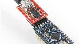
For users interested in using the serial UART protocol to communicate with the sensor through a computer's USB port, you can connect a serial-to-USB connector directly to the board.
Before connecting, make sure to add a solder jumper on PS1 to configure the board for UART protocol as stated earlier in the Hardware Overview.
| PS0 | PS1 | Interface | Note |
|---|---|---|---|
| 0 | 0 | I2C | |
| 1 | 0 | UART-RVC | |
| 0 | 1 | UART | Add solder blob to the jumper to set to 1. |
| 1 | 1 | SPI |
The table below shows how to connect the VR IMU Breakout BNO086's UART port to a Serial Basic. You can angle header pins against the PTHs and hold the boards together with one hand for a temporary connection. However, we recommending soldering to the connection for a reliable and secure connection. You can choose between a combination of header pins and jumper wires, or stripping wire and soldering the wire directly to the board.
| VR IMU Breakout - BNO086 | 3.3V Serial Basic | Wire Color |
|---|---|---|
| GND | GND | BLK |
| CTS | ||
| 3V3 | 3.3V | |
| RXI | TXO | |
| TXO | RXI | |
| DTR | GRN |
Note
You will need to be careful when soldering header pins to the edge pins and the UART located at the center of the board. For users that solder header pins to the edge of the board to mate with a breadboard, you will need to solder header pins facing the other way for the UART header so that the center pins do not connect to the same rails. The same goes with users that are using right angle header pins as well.
Of course, you can cut a six wire jumper wire cable and wire strip them before connecting to the 1x6 header as well.
The UART interface is in the middle of the board, with the black and green pins labeled as BLK and GRN. As stated earlier, these serial pins have been arranged to work with our Serial Basic board to make interfacing to a computer simple and fast. Once the header pins are soldered, align the GRN and BLK labels so that the serial connection is properly connected and slide the male header pins into the female header sockets.
 |
Connecting via SPI
For users interested in using the SPI protocol to communicate with the sensor, there are few examples in the Arduino Library. You can use those examples as a basis to adjust the I2C examples to use it with SPI.
Before connecting, make sure to add a solder jumper on PS0 and PS1 to configure the board for SPI protocol as stated earlier in the Hardware Overview.
Note
As of v1.0.3, the I/O pins have also been changed for the CS, reset, interrupt pins! Make sure to adjust your connections accordingly.
| PS0 | PS1 | Interface | Note |
|---|---|---|---|
| 0 | 0 | I2C | |
| 1 | 0 | UART-RVC | |
| 0 | 1 | UART | |
| 1 | 1 | SPI | Add solder blob to the jumpers to set to 1. |
The table below shows how to connect the SparkFun IoT RedBoard - ESP32 to the VR IMU Breakout BNO086's SPI port. As stated earlier for the I2C, you could use IC hooks for initial testing. However, we recommending soldering to the connection for a reliable and secure connection. You can choose between a combination of header pins and jumper wires, or stripping wire and soldering the wire directly to the board.
| RedBoard IoT - ESP32 | VR IMU Breakout - BNO086 |
|---|---|
| 3.3V | 3.3V |
| GND | GND |
| D5 | CS |
| PICO (D23) | SI |
| POCI (D19) | SO |
| SCK (D18) | SCK |
| A4 | INT |
| A5 | RST |
 |
Note
For users that are connecting the BNO086 to a MicroMod Machine Learning Board and MicroMod Artemis Processor, you will need to redefine a few pins. We recommend redefining the following pins in the example code.
Note that SPI_CS on the MicroMod Machine Learning Board is only routed to the CS pin for the microSD card. D0 is also used as the CS pin for the on-board camera via SPI. D0 will work but if you are using a camera, then this would cause a conflict. A good alternative pin to use in this case would be PWM1.
Additionally, A0 and A1 are meant to be only used as input pins and for ADC. The MicroMod Artemis Processor has op amps and scaling from 3.3V to 3V on both of those analog pins.
Installing the Arduino Library
Arduino
Arduino IDE
This example assumes you are using the latest version of the Arduino IDE on your desktop. If this is your first time using Arduino IDE and an library, please review the following tutorials.
Board Definitions
For the scope of this tutorial, we will be using the SparkFun IoT RedBoard - ESP32 Development Board. This Library also works with the SAMD51. For users that decide to use the SAMD51, make sure to use the Arduino SAMD Core and SparkFun SAMD boards before selecting the SAMD51 board definition.
If you have not installed a board definition before, please review the following tutorial as well.
USB-to-Serial Drivers
If you've never connected an CH340 device to your computer before, you may need to install drivers for the USB-to-serial converter. Check out our section on "How to Install CH340 Drivers" for help with the installation.
The SparkFun VR IMU BNO08X Arduino Library provides a quick way to interact with the interfaces on the SparkFun VR IMU Breakout - BNO086 (Qwiic). Install the library through the Arduino Library Manager tool by searching for "SparkFun BNO08X". Users who prefer to manually install the library can get it from the GitHub Repository or download the .ZIP by clicking the button below:
Note
This library is different from the original BNO080 Arduino Library. Most of the examples from the old Arduino Library were ported to the BNO08X Arduino Library. We recommend using this library for the BNO08X as it processes the data better.
Arduino Examples
Now that we have our library installed, we can get started playing around with our examples to learn more about how the IMU behaves. From there we'll be able to build our own custom code to integrate the sensor into a project.
Note
As of Arduino Library v1.0.3, the following line of code has been included for microcontrollers with built-in native USB (i.e. the SAMD51). This can be commented out when using the BNO086 in projects that are not using a Serial Terminal.
while(!Serial) delay(10); // Wait for Serial to become available.
// Necessary for boards with native USB (like the SAMD51 Thing+).
// For a final version of a project that does not need serial debug (or a USB cable plugged in),
// Comment out this while loop, or it will prevent the remaining code from running.
Example 1 - Rotation Vector
This first example gets us started taking a reading of our complex valued rotation vector, or quaternion, which tells us how we are oriented. Open the example by navigating to File > Examples > SparkFun BNO08X Cortex Based IMU > Example_01_RotationVector.
Select your board in the Tools menu (in our case SparkFun ESP32 IoT RedBoard) and the correct Port it enumerated on and click "Upload". After uploading the code, open the Serial Monitor or terminal emulator of your choice with the baud rate set to 115200.
You should see an output of the quaternion values (i.e. i, j, k, and real) and the accuracy in radians.
 |
Example 2 - Accelerometer
Examples 2 deals with pulling the accelerometer values from our sensor to figure out how it is moving. Open the example by navigating to File > Examples > SparkFun BNO08X Cortex Based IMU > Example_02_Accelerometer.
Select your board in the Tools menu (in our case SparkFun ESP32 IoT RedBoard) and the correct Port it enumerated on and click "Upload". After uploading the code, open the Serial Monitor or terminal emulator of your choice with the baud rate set to 115200.
You should see an output of the accelerometer values for x, y, and z in m/s2. If the breakout board is on the table with the z-axis pointed up to the ceiling, you should see a value close to the value of about +9.81 m/s. Of course, that value can vary depending on where you are on Earth](https://en.wikipedia.org/wiki/Gravity_of_Earth) or if the board is not fully rested on a flat table.
 |
Example 3 - Gyro
In example 3, we'll pull values from the IMU's gyroscope to get a vector for our angular velocity. Open the example by navigating to File > Examples > SparkFun BNO08X Cortex Based IMU > Example_03_Gyro.
Select your board in the Tools menu (in our case SparkFun ESP32 IoT RedBoard) and the correct Port it enumerated on and click "Upload". After uploading the code, open the Serial Monitor or terminal emulator of your choice with the baud rate set to 115200.
You should see the angular velocity for x, y, and z in radians/s. Try rotating the board about each axis. You should see the values change depending on the direction that you rotate the board.
 |
Also, check out the values in a graph by opening the Serial Plotter to the same baud rate to see the readings from each gyroscope channel plotted against each other. Rotate the IMU and see how the values respond, I got the following output just letting the IMU swing on its cable.
 |
Note
The range for the Arduino Serial Plotter along x-axis is a bit limited in Arduino IDE v2+ as opposed to previous versions like Arduino v1.8.19. There is a feature request relating to the Arduino Serial Plotter in the GitHub repo for the Arduino IDE. If you would like a bigger range, try opening the Arduino Serial Plotter in an older Arduino IDE like Arduino v1.8.19. Just make sure to adjust the baud rate to 115200.
 |
Example 4 - Magnetometer
The following example will get us reading the component vectors for the magnetic field. Open the example by navigating to File > Examples > SparkFun BNO08X Cortex Based IMU > Example_04_Magnetometer.
Select your board in the Tools menu (in our case SparkFun ESP32 IoT RedBoard) and the correct Port it enumerated on and click "Upload". After uploading the code, open the Serial Monitor or terminal emulator of your choice with the baud rate set to 115200.
You should see the magnetometer values for x, y, and z in µTesla and the accuracy. Try moving the magnetometer around aligning the sensor with the North Pole. You can also try placing a weak magnet near the sensor to see the values increase. In this case, I placed a weak magnet which increased the magnitude of the field along the z-axis.
 |
Warning
Note that you will want to be careful about placing the sensor too close to a magnet (especially a strong magnet) as this can potentially damage the sensor.
Example 5 - Step Counter
The BNO080 has some really neat built-in features due to its built in Cortex. One of these is a built in step counter. Open the example by navigating to File > Examples > SparkFun BNO08X Cortex Based IMU > Example_05_StepCounter.
Select your board in the Tools menu (in our case SparkFun ESP32 IoT RedBoard) and the correct Port it enumerated on and click "Upload". After uploading the code, open the Serial Monitor or terminal emulator of your choice with the baud rate set to 115200.
Try holding the sensor or attaching to your body while connect to a laptop and walk around. You should see a value close to the number of steps that you have taken. In this case, I just walked away from my table and back.
 |
Example 6 - Stability Classifier
This example sketch allows us to use the built-in stability classifier to figure out how stable the IMU is. Open the example by navigating to File > Examples > SparkFun BNO08X Cortex Based IMU > Example_06-StabilityClassifier.
Select your board in the Tools menu (in our case SparkFun ESP32 IoT RedBoard) and the correct Port it enumerated on and click "Upload". After uploading the code, open the Serial Monitor or terminal emulator of your choice with the baud rate set to 115200.
Give the BNO086 a second to measure and process the sensor values. The sensor will provide an output classifying an activity. In the output below, the sensor determined that the board was resting on a table... which it was! Amazing!
 |
As stated in the datasheet, the sensor uses both the accelerometer and gyroscope to determine the sensor's stability: on table, stationary, stable, motion. If the sensor does not know what is happening, the output will tell you that it was an "unknown classification."
Example 7 - Activity Classifier
The activity classifier is somewhat similar to the stability classifier in that it uses the on-board Cortex to determine what activity the IMU is doing. Open the example by navigating to File > Examples > SparkFun BNO08X Cortex Based IMU > Example_07_ActivityClassifier.
Select your board in the Tools menu (in our case SparkFun ESP32 IoT RedBoard) and the correct Port it enumerated on and click "Upload". After uploading the code, open the Serial Monitor or terminal emulator of your choice with the baud rate set to 115200.
Give the BNO086 a second to measure and process the sensor values. The sensor will provide an output classifying an activity and how confident it was. In the output below, the sensor determined that I was on the move and walking around my desk, which I was!
 |
The BNO086 can determine the following activities:
- In vehicle
- On bicycle
- On foot
- Still
- Tilting
- Walking
- Running
- On stairs
If the sensor is not able to determine what is happening, the output will tell you that it was an "Unknown."
Example 8 - Advanced Configuration
This example shows us how to configure the sensor on different addresses and I2C buses. Make sure to close the ADR jumper by adding a solder blob. You will also need to manually connect the I2C data and clock pins to the alternative port. For a quick test, you could use the Qwiic cable with breadboard jumpers to connect the breakout board to the RedBoard IoT - ESP32's header sockets. Of course, soldering wire directly to the PTH is better for a more secure connection.
| RedBoard IoT - ESP32 | VR IMU Breakout - BNO086 |
|---|---|
| 3.3V | 3.3V |
| GND | GND |
| SCL1 (D17) | SCL |
| SDA1 (D25) | SDA |
| A4 | INT |
| A5 | RST |
 |
Open the example by navigating to File > Examples > SparkFun BNO08X Cortex Based IMU > Example_08_AdvancedConfig.
Select your board in the Tools menu (in our case SparkFun ESP32 IoT RedBoard) and the correct Port it enumerated on and click "Upload". After uploading the code, open the Serial Monitor or terminal emulator of your choice with the baud rate set to 115200.
 |
Example 9 - Linear Accelerometer
The following example is similar to example 2, however we are reading the linear acceleration. What does this mean? Well, it's acceleration with gravity (~9.8m/s2) removed from the data! Open the example by navigating to File > Examples > SparkFun BNO08X Cortex Based IMU > Example_09_LinearAccelerometer.
Select your board in the Tools menu (in our case SparkFun ESP32 IoT RedBoard) and the correct Port it enumerated on and click "Upload". After uploading the code, open the Serial Monitor or terminal emulator of your choice with the baud rate set to 115200.
 |
Example 10 - Timestamp
This example is pretty much like example 1. The difference is that we add a timestamp for each rotation vector. Open the example by navigating to File > Examples > SparkFun BNO08X Cortex Based IMU > Example_10_TimeStamp.
Select your board in the Tools menu (in our case SparkFun ESP32 IoT RedBoard) and the correct Port it enumerated on and click "Upload". After uploading the code, open the Serial Monitor or terminal emulator of your choice with the baud rate set to 115200.
 |
Example 11 - Raw Readings
This example shows how to output the raw acceleration, gyroscope, and magnetometer values. Open the example by navigating to File > Examples > SparkFun BNO08X Cortex Based IMU > Example_11_RawReadings.
Select your board in the Tools menu (in our case SparkFun ESP32 IoT RedBoard) and the correct Port it enumerated on and click "Upload". After uploading the code, open the Serial Monitor or terminal emulator of your choice with the baud rate set to 115200.
 |
Example 12 - Gyro Integrated Rotation Vector
This example shows how to use the gyro integrated rotation vector. Open the example by navigating to File > Examples > SparkFun BNO08X Cortex Based IMU > Example_12-GyroIntegratedRotationVector.
Select your board in the Tools menu (in our case SparkFun ESP32 IoT RedBoard) and the correct Port it enumerated on and click "Upload". After uploading the code, open the Serial Monitor or terminal emulator of your choice with the baud rate set to 115200.
 |
Example 13 - Euler Angles
Open the example by navigating to File > Examples > SparkFun BNO08X Cortex Based IMU > Example_13_EulerAngles.
Select your board in the Tools menu (in our case SparkFun ESP32 IoT RedBoard) and the correct Port it enumerated on and click "Upload". After uploading the code, open the Serial Monitor or terminal emulator of your choice with the baud rate set to 115200.
 |
Example 14 - Tare
Open the example by navigating to File > Examples > SparkFun BNO08X Cortex Based IMU > Example_14_Tare.
Select your board in the Tools menu (in our case SparkFun ESP32 IoT RedBoard) and the correct Port it enumerated on and click "Upload". After uploading the code, open the Serial Monitor or terminal emulator of your choice with the baud rate set to 115200.
 |
Example 15 - Gravity
Open the example by navigating to File > Examples > SparkFun BNO08X Cortex Based IMU > Example_15_Gravity.
Select your board in the Tools menu (in our case SparkFun ESP32 IoT RedBoard) and the correct Port it enumerated on and click "Upload". After uploading the code, open the Serial Monitor or terminal emulator of your choice with the baud rate set to 115200.
 |
Example 16 - Uncalibrated Gyro
Open the example by navigating to File > Examples > SparkFun BNO08X Cortex Based IMU > Example_16_UncalibratedGyro.
Select your board in the Tools menu (in our case SparkFun ESP32 IoT RedBoard) and the correct Port it enumerated on and click "Upload". After uploading the code, open the Serial Monitor or terminal emulator of your choice with the baud rate set to 115200.
 |
Installing the Processing Library
Note
Processing is a software that enables visual representation of data, among other things. If you've never dealt with Processing before, we recommend you also check out the Arduino to Processing tutorial. Follow the below button to download and install Processing.
Note
At the time of writing this tutorial, we used Arduino IDE v2.1.1 and SparkFun VR IMU BNO08X Arduino Library v1.0. We also used Processing IDE v3.5.3 and toxiclibs Processing Library v0021. We also tested the demo and verified that it works with Processing v4.3.
Manually Install the toxiclibs Processing Library v0021
Note
We were unable to search for the toxiclibs in Processing's Contribution Manager in order to automatically install the library. Instead, we manually installed the Processing Library.
Before running the "Serial Cube Rotate" processing demo, you will also need to manually install the ToxicLibs Processing Library v0021 by "Karsten Schmidt". This is a library used for computational design. Head to the v0021 release and download "toxiclibs-complete-0021.zip".
Similar to an Arduino Library, there is a certain file structure that Processing requires to properly install a Processing Library. After downloading, unzip the files and open the toxiclibs-complete-0021 folder. For Windows, copy all the contents of the folder (except for _MACOSX) into the Processing's libraries folder (in this case, C:\Users...\Documents\Processing\libraries). Again, we'll assume that you are using Processing IDE v3.5.3.
 |
Processing Example
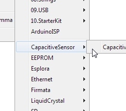
This section is a fun bonus example that rotates a cube in Processing based on the BNO086's sensor rotation vector's readings. This extra example is not included in the SparkFun VR IMU BNO08X Arduino Library as it requires Processing. To grab it, go ahead and download or clone the SparkFun VR IMU Breakout BNO086 QWIIC hardware repo.
Note
The modified Arduino example has been updated to reflect the changes in Arduino Library v1.0.3.
Upload Modified Arduino Example 1's Rotation Vector
Processing listens for serial data, so we'll need to get our Arduino (i.e. RedBoard IoT - ESP32) to produce serial data that makes sense to Processing. For this case, we will be using the example 1's rotation vector. However, we will be modifying it by sending only the comma separated values to the serial port.
After unzipping the compressed files, navigate to the hardware repo's folder and open the example: ... SparkFun_VR_IMU_Breakout_BNO086_QWIIC > Software > Arduino > Example_01_RotationVector_MOD > Example_01_RotationVector_MOD.ino. This modified sketch simply prints a list of our quaternions separated by a comma over serial for Processing to listen to. You will also notice that the sequence of values is adjusted slightly for the Processing by moving the Real before the real value before i, j, and k. We also adjusted the baud rate to allow Processing some time to process the data.
Select your board in the Tools menu (in our case SparkFun ESP32 IoT RedBoard) and the correct Port it enumerated on. Then click "Upload". After uploading the code, open the Serial Monitor or terminal emulator of your choice with the baud rate set to 9600.
 |
Run the "Serial Cube Rotate" Processing Demo
Once this sketch is uploaded, we need to tell Processing how to turn this data into a visualization. The Processing sketch to do this is located one folder above the Arduino sketch: ... SparkFun_VR_IMU_Breakout_BNO086_QWIIC > Software > Processing > Serial_Cube_Rotate.pde. Open the Serial_Cube_Rotate.pde file in Processing.
Attempting to run the Processing sketch will show us available serial ports in the debug window from this line of code:
Identify which serial port your Arduino is on. For instance, my RedBoard IoT - ESP32 is on COM17, which corresponds to [6] in the image below, so I will need to change 0 to 6 in the following line to ensure Processing is listening to the correct serial port.
 |
Once we've done this, we should be able to run the Processing sketch and it will give us a nice visualization of how our IMU is oriented in 3D space as a cube. Try rotating the IMU to see how it responds. You should get a neat little output like the one in the below GIF with Nick Poole's hand.
 |
Troubleshooting
General Troubleshooting Help
Note
Not working as expected and need help?
If you need technical assistance and more information on a product that is not working as you expected, we recommend heading on over to the SparkFun Technical Assistance page for some initial troubleshooting.
If you don't find what you need there, the SparkFun Forums are a great place to find and ask for help. If this is your first visit, you'll need to create a Forum Account to search product forums and post questions.
If you are having problems connecting to the BNO086 and you see the following output after resetting the RedBoard IoT - ESP32 in the Serial Monitor, there could be a few reasons why.
 |
If you are using the I2C examples, try checking your connections and the Qwiic cable for loose connections. Also, ensure that the correct I2C's address jumper is selected as well as the jumpers for the protocol selection. The communication may also be out of sync with the BNO086. You may need to power cycle the board by removing the cable from the connector and reconnecting it.
You may also want to try connecting the interrupt and reset pins to the board for a hardware reset. Make sure to check example 17 for more information about modifying the example to include the hardware reset.
Resources
Now that you've successfully got your SparkFun Qwiic VR IMU Breakout (BNO086) up and running, it's time to incorporate it into your own project! For more information, check out the resources below:
- Schematic (PDF)
- Eagle Files (ZIP)
- Board Dimensions (PNG)
- BNO086
- Fritzing Part
- Arduino Library - SparkFun's Arduino Library for the BNO08X
- Processing Library - ToxicLibs v0021
- GitHub Hardware Repo
- SFE Product Showcase