Introduction
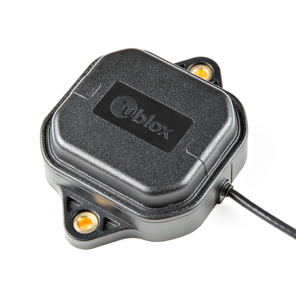
The SparkFun GNSS-RTK L1/L5 Breakout - NEO-F9P (Qwiic) is a high precision GNSS board with equally impressive configuration options. Utilizing both the L1 and L5 bands, the NEO-F9P delivers improved performance under challenging urban environments because the L5 signals fall within the protected ARNS (aeronautical radionavigation service) frequency band. This band is less subject to RF interference.
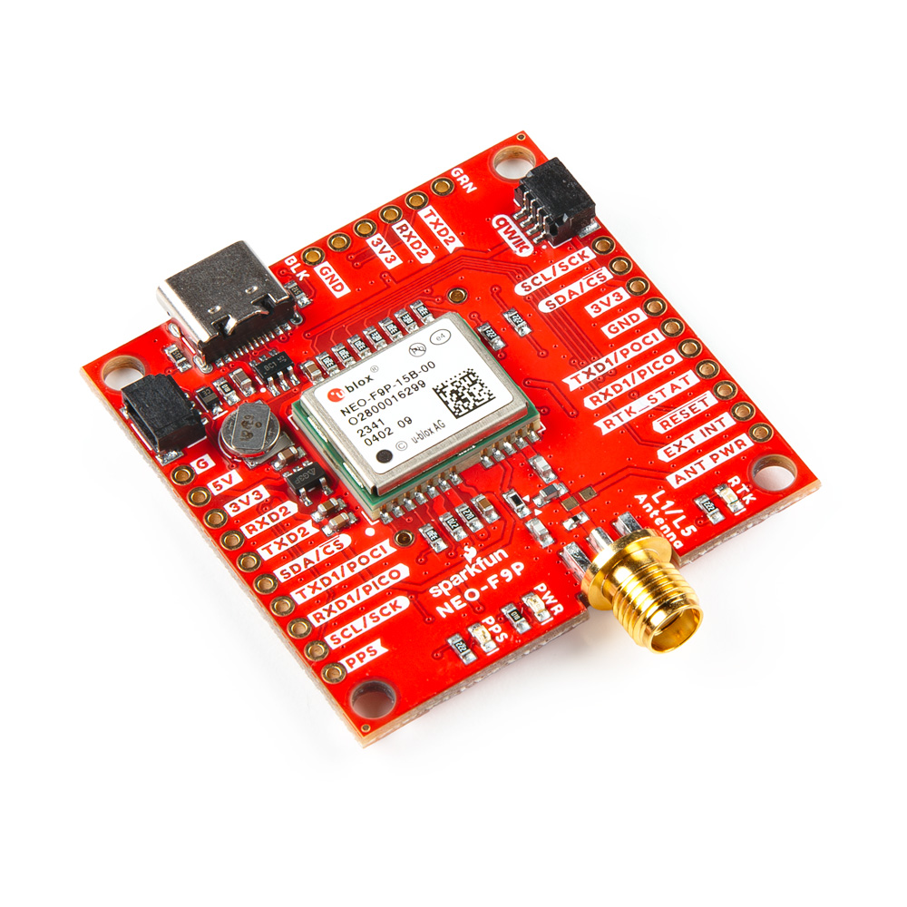
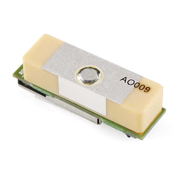
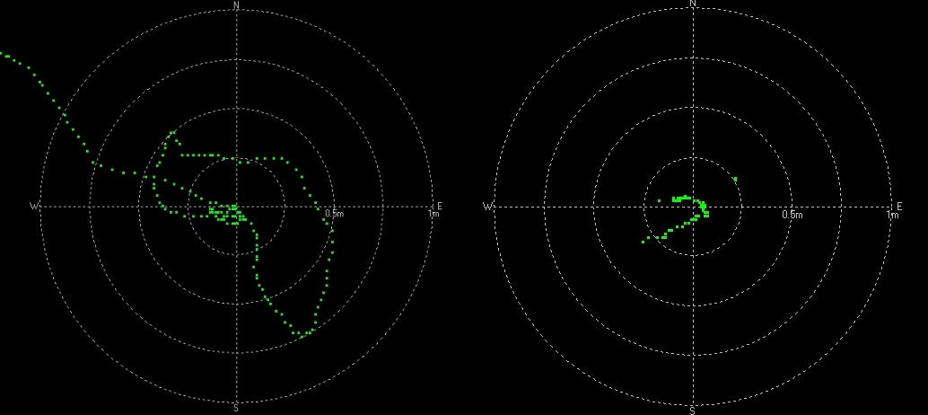
Similar to the ZED-F9P, the NEO-F9P module is a 184-channel u-blox F9 engine GNSS receiver, meaning it can receive signals from the GPS, GLONASS, Galileo, and BeiDou constellations with 10mm, three-dimensional accuracy! That's right; such accuracy can be achieved with an RTK navigation solution when used with a correction source. With this board, you will be able to know where your (or any object's) X, Y, and Z location is within roughly the width of your fingernail! Of course, the requirements for high precision GNSS requires a clear view of the sky (sorry, no indoor location) and a stream of correction data from an RTCM source. As long as you have two high precision breakout boards, or access to an online correction source, your NEO-F9P can output latitude, longitude, and altitude with centimeter grade accuracy. The module supports the concurrent reception of four GNSS systems. This module features a survey-in mode allowing the module to become a base station and produce RTCM 3.x correction data.
In this tutorial, we'll go over the hardware and how to hookup the breakout board. We will also go over a basic Arduino example to get started!
Required Materials
To follow along with this tutorial, you will need the following materials. You may not need everything though depending on what you have. Add it to your cart, read through the guide, and adjust the cart as necessary.
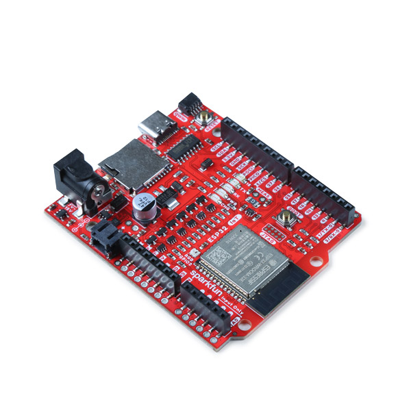
- 1x SparkFun IoT RedBoard - ESP32 Development Board [WRL-19177]
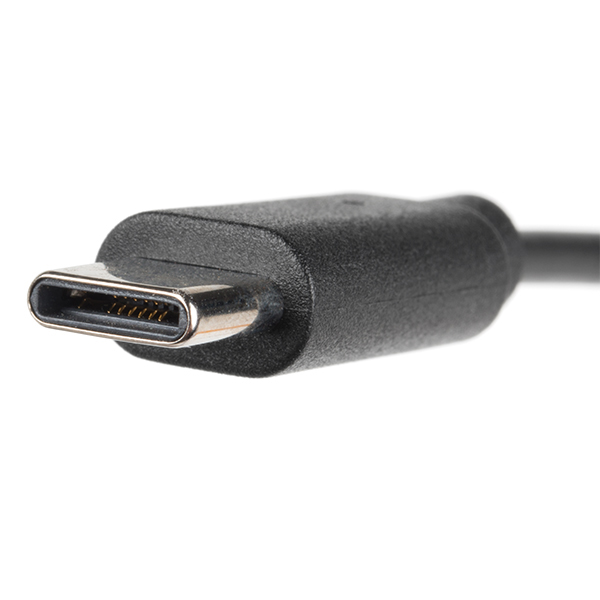
- 1x Reversible USB A to C Cable - 0.8m [CAB-15425]
- 1x SparkFun GNSS-RTK L1/L5 Breakout - NEO-F9P (Qwiic) [GPS-23288]
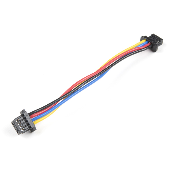
- 1x Qwiic Cable
- Flexible Qwiic Cable - 50mm [PRT-17260], for short distances
- Flexible Qwiic Cable - 500mm [PRT-17257], for those that need to wire the board farther away from your microcontroller
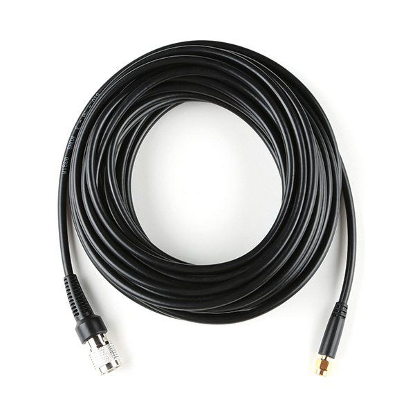
- 1x Reinforced Interface Cable - SMA Male to TNC Male (10m) [CAB-21740]
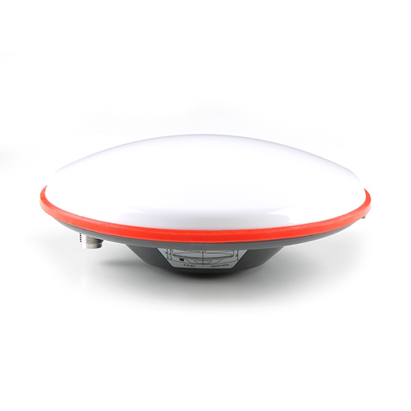
- 1x GNSS L1/L5 Multi-Band High Precision Antenna - 5m (SMA) [GPS-23814]
GNSS Accessories (Optional)
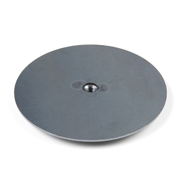
Depending on your setup, you may need the following mounting hardware. As included earlier in the required materials, the antenna ground plate below is needed when using multi-band antennas that do not have a good ground plane.
For users that decide to use the SPK6618H multi-band antenna as an alternative, users would not need to include the antenna ground plate. The mounting hardware listed below is also typically used with the SPK6618H multi-band antennas. The reinforced interface cable between the SMA to TNC also needed for the SPK6618H multi-band antennas.
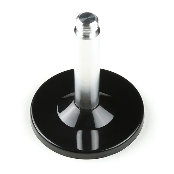
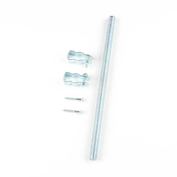
- GNSS Magnetic Mount [PRT-21257]
- GNSS Antenna Mounting Hardware Kit [KIT-22197]
- Reinforced Interface Cable - SMA Male to TNC Male (10m) [CAB-21740]
- GNSS Multi-Band L1/L2/L5 Surveying Antenna - TNC (SPK6618H) [GPS-21801]
Radios (Optional)
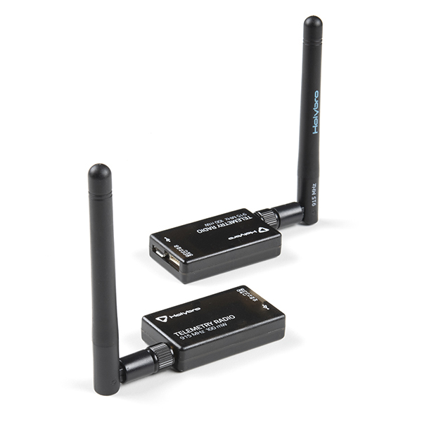
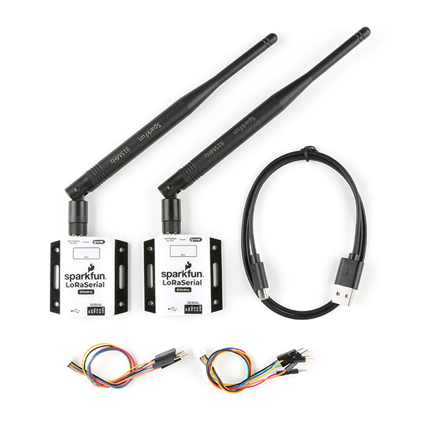
For users that require radios to transmit RTK correction data, you could use the following radios.
- SiK Telemetry Radio V3 - 915MHz, 100mW [WRL-19032]
- SparkFun LoRaSerial Kit - 915MHz (Enclosed) [WRL-20029]
Tools (Optional)
You will need a soldering iron, solder, and general soldering accessories for a secure connection when using the plated through holes.
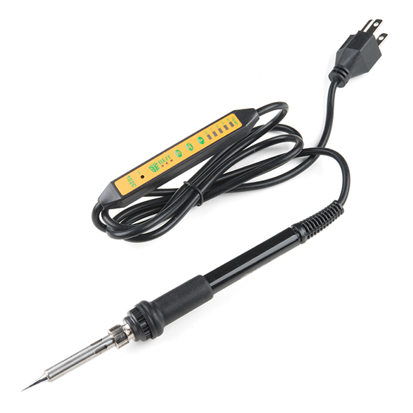
- Soldering Iron [TOL-14456]
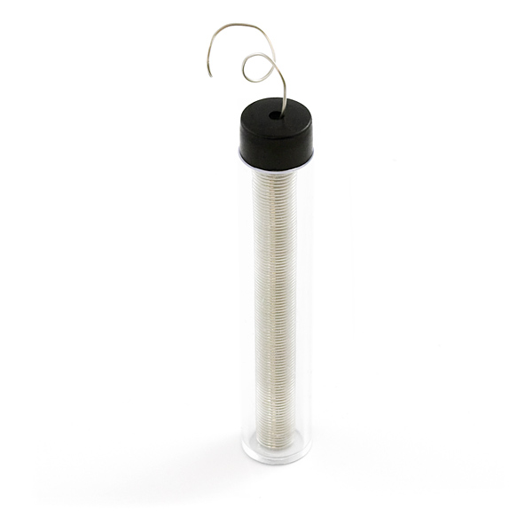
- Solder Lead Free - 15-gram Tube [TOL-9163]
- Flush Cutters - Xcelite [TOL-14782]
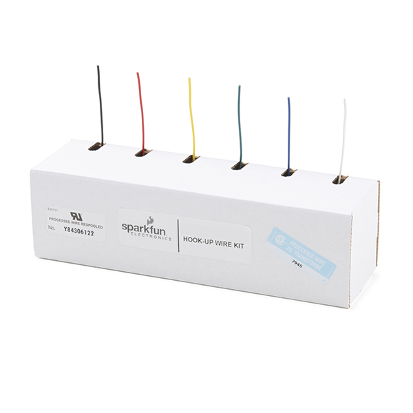
- Hook-Up Wire - Assortment (Stranded, 22 AWG) [PRT-11375]
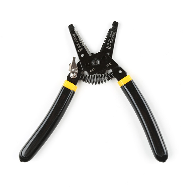
- Wire Stripper - 20-30 AWG Solid (22-32 AWG Stranded) [TOL-22263]

Prototyping Accessories (Optional)
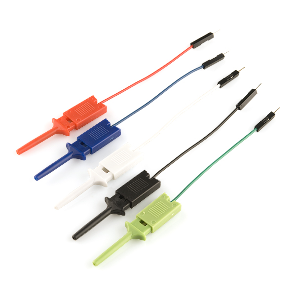
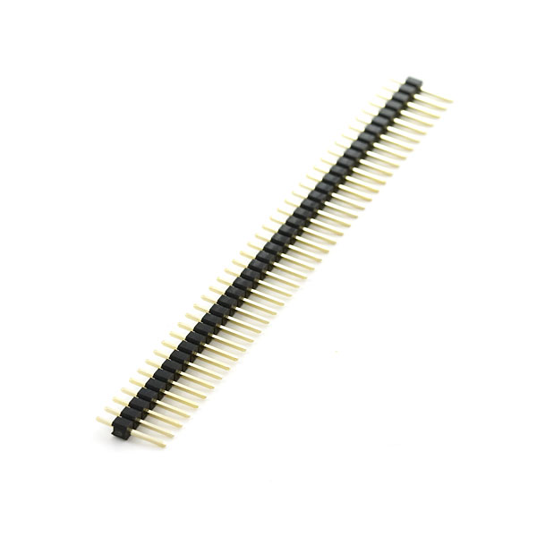
For those using radios to connect a base station and rover together, you will need to connect to the PTHs. You could use IC hooks for a temporary connection depending on your setup and what you have available. Of course, you will want to the solder header pins for a secure connection. Below are a few prototyping accessories that you may want to consider.
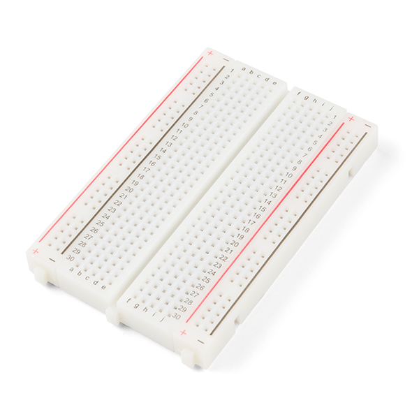
- Breadboard - Self-Adhesive (White) [PRT-12002]
- IC Hook with Pigtail [CAB-09741]
- Break Away Headers - Straight [PRT-00116]
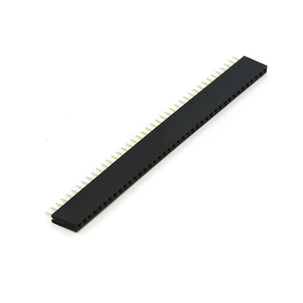
- Female Headers [PRT-00115]
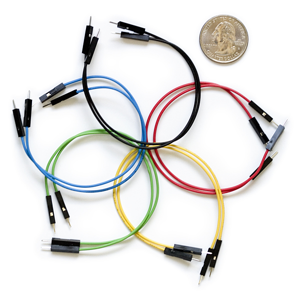
- Jumper Wires Premium 6" M/M Pack of 10 [PRT-08431]
Suggested Reading
If you aren't familiar with the Qwiic Connection System, we recommend reading here for an overview.

If you aren’t familiar with the following concepts, we also recommend checking out a few of these tutorials before continuing.


You may also be interested in the following blog posts on GNSS technologies.
-

GPS vs GNSS
-

What is Correction Data?
-

Real-Time Kinematics Explained
-
New Video: Unlocking High-Precision RTK Positioning