This tutorial will guide you through how to build your own wireless and/or wired headphones with ambient microphones. We start with some off-the-shelf headphones intended for use while lawn mowing, and then hack in some new electronics to allow wireless (BT), auxiliary 3.5mm TRS input, and stereo ambient microphones. The original purpose of this project was to make it easy and safe to play loud music with a rock band in the basement, however, the inclusion of the natural sounds around you into your listening experience can be useful in many other situations.

Background
The first prototype design was sparked up around the time I was designing the Qwiic Speaker Amp in August of 2022. Now, over a year later, it has been through three major versions:
-

August 2022 - "V1" Qwiic Speaker Amp
-

November 2022 - "V2" WM8960 Codecs
-

February 2023 - "V3" Custom PCB


With this project, I was trying to solve three problems:
-
) I want to be able to lower all barriers to practicing music. The less things I have to set up, the better!
-
) When I play drums, I need to protect my ears from getting damaged from exposure to extremely loud sounds. To do this, I usually wear in-ear monitors (IEMs). IEMs are kind of like headphones, but they are more like earbuds. They are usually custom-molded to your ear canal. In this way, they are actually working much like ear plugs and blocking out loud sounds while still providing sound to your ears. In order to get a great monitor mix, I then need to set up mics and a sound mixer. You can accomplish this with headphones too, but most do not provide a safe amount of sound-isolation. IEMs are great, but they are also very expensive. They can range from $300 to $3,000.
-
) My eight year old son is playing loud music more and more (acoustic drums, amplified guitar and keyboards), and I want him to be able to protect his hearing while still being able to rock out and hear the music clearly. Over-the-ear hearing protection (aka “Ear Muffs”), do a great job of protecting your hearing, but they also dampen the sound way too much. In addition to missing out on many of the mid and high frequencies, it can be very difficult to hear your own instrument and even your band mates.
My idea of a perfect solution:
-
Over-the-ear headphones that have stereo ambient mics to mix in!
-
Very easy to “pop on”, with no cables attached. Nothing to wire up, just pop them on and go.
-
Mix in a desired level of the ambient mics using a single knob, essentially a “more ears” knob - right there on my headphones, at the ready to adjust as needed.
-
Battery powered, 100% self contained, wireless. During some jam sessions with the kiddos, we will quickly trade instruments. We need to be able to jump around the room, free from wires and/or plugging and unplugging things.
-
The ability to mix in a line level audio source (for practice tracks or other monitor signals from a mixer). This could come in handy for more advanced monitor sound system setups, where maybe I am getting a feed from the mixer that contains the rest of the musicians I am playing with.
-
And icing on the cake, a Bluetooth® optional input. This last thing was really more useful for me during my solo practice sessions. I can load my phone up with my practice tracks and wirelessly connect to my headphones. Also, of course, useful for general listening.
Headphones
For this project, we chose over-the-ear headphones that provide a large amount of sound dampening (30dB). These types of headphones are also called ear-muffs and are often marketed for use during loud construction work or lawn mowing.
The exact headphones we chose to start with were the following:
When using this type of lawn-mowing headphones without any modification, they provide adequate sound dampening to protect your ears in extremely loud places. However, with this benefit, you also lose the ability to hear your natural surroundings clearly. Usually, it is described as sounding a bit like two pillows are held to either ear. This is because the passive sound dampening is blocking most of the high frequencies.
In order to get the sound clarity back, we need to use ambient microphones. The correct type of microphone can accept the loud sound sources without distortion. This type of microphone is said to have a high acoustic overload point, or AOP. We can send that clean audio signal from the microphones into the headphones at a safe listening level. In addition to a high AOP, the microphones also need to have a large signal to noise ratio (SNR), which helps avoid having too much "hiss" in the audio signal. Choosing the best microphone for the job turned out to involve a lot of testing. More on this later.
The Modification
In addition to sound dampening, the original electronics included the ability to listen to FM radio and plug in a 3.5mm TRS audio cable. In this tutorial, we will remove the stock electronics, and replace them with the SparkFun ESP32 Thing Plus and the WM8960 Audio Codec. The following two pictures show a comparison of the original electronics (blue) and our new version (green/red/black). We took pictures of the topside and backside of each for a more thorough comparison.
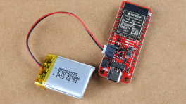
The new version actually includes three PCBs. The red microcontroller is the SparkFun Thing Plus ESP32. The black PCB is an early prototype of the SparkFun Audio Codec Breakout. The green PCB below is a custom "motherboard" that makes some connections between the two dev boards and provides the on/off/volume knob, 3.5mm TRS input, and mounting holes to mount this entire assembly into headphone can.
-

Topside
-

Backside


Using the WM8960 Audio Codec Breakout, we can mix together sound sources. In this use case, we are mixing together three sound sources:
-
) Wireless (aka "BT") audio from the ESP32 to the codec via I2S audio.
-
) Wired audio from a 3.5mm TRS audio jack (common headphone cable connector).
-
) Ambient microphones mounted to either sides of each ear-can, to provide a pair of stereo room mics to your listening experience. In a way, these microphones are "giving you your ears back". Most importantly, doing so at a safe volume, to prevent hearing loss.
Required Materials
To follow along with this tutorial, you will need the following materials. You may not need everything though depending on what you have. Add it to your cart, read through the guide, and adjust the cart as necessary.
- 1x SparkFun Thing Plus - ESP32 WROOM (USB-C) [WRL-20168]
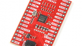
- 1x SparkFun Audio Codec Breakout - WM8960 (Qwiic) [BOB-21250]
- 1x Set of "Mowing" Headphones aka "ear muffs"
- 2x Ambient Microphones [PUI-AOM-5053L-HD3-LW100-R]
- 1x Custom "motherboard" PCB (open-source design on GitHub here, you'll just need to order from your favorite fab house!)
- 1x USB-C Cable
- Our USB 2.0 A to C Cable [CAB-15092] will do nicely
- Our USB 3.1 A to C Cable [CAB-14743] is a good choice too
- 1x PET Expandable Braided Sleeving
- 1x 3.5mm Audio Jack (SMD) [SJ-3523-SMT-TR]
- 1x Potentiometer with Switch [652-PTR902-2015FA203]
Tools
You will need to solder various connections using hook-up wire, microphone cable, PTH/SMD parts, and header pins. You may already have a few of these items but if not, the tools and hardware below will help. See suggested reading below for any help with learning or refreshing these assembly skills.
- 1x Hook-Up Wire - Assortment (Stranded, 22 AWG) [PRT-11375]
- 2x Break Away Male Headers - Right Angle [PRT-00553]
- Wire Stripper - 20-30 AWG Solid (22-32 AWG Stranded) [TOL-22263]
- Soldering Iron [TOL-14456]
- Solder Lead Free - 15-gram Tube [TOL-9163]
- Hot Glue Gun and Hot Glue
- Dremel or similar tool for cutting out holes for ambient mics
Suggested Reading
If you aren’t familiar with the following concepts, we also recommend checking out a few of these tutorials before continuing.

Hardware Overview
Block Diagram
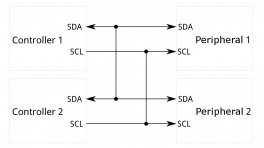
Here is a high-level block diagram of the sound system inside the headphones. The Audio Codec is central to this design. It handles all of the sound inputs and outputs. The ESP32 Thing Plus is still the "brain", and it is necessary to setup and control the codec with I2C. The ESP32 also receives the wireless audio (BT), and then sends that to the codec, digitally, with I2S audio data lines.

High level block diagram of the headphone system.
Exploded View
Here is an exploded view of the headphones. It took a little experimenting and tinkering to eventually disassemble all of the parts. In this section, we will share a few techniques we learned along the way during this hack.

Exploded view of the headphone system.
Foam Removal
Removing the foam was pretty straight forward. You can use a flat head screwdriver or pliers, but be careful. As you can see, I accidentally ripped the foam apart when I pulled a bit too hard.

Oops! I accidentally ripped the foam.
It's really best to take it slowly and pull it gently, little-by-little. I really got the hang of this by the end of this project. I must have taken mine apart nearly 50 times as I fine tuned the wiring and swapped out microphones during testing. Hopefully, by reading this tutorial, you can keep this dis-assembly and reassembly cycle to a minimum. :)
Screws
After you remove the foam, this will expose the screws that hold the outer and inner parts of each can together.

Two small screws hold the cans together.
The screws are located back behind the black plastic. Because of the angle, they can be a little difficult to access, but with a small Phillips head screwdriver and the right amount of pressure, it can be done.
Knob and PCB removal
When the inner screws are removed, the cans come apart, and then you will see the original electronics (blue). The volume knob is simply pressure fitted onto the potentiometer shaft, so you can pull that directly off. Unscrew the potentiometer mounting nut and the four mounting screws, and you will then be able to remove the original electronics.

Knob, nut, and 4 mounting screws removed.
Custom PCB Assembly
Note, the custom PCB is not 100% necessary to complete this project. My early prototype "V2" was a hand-wired version. If you decide to go that route, then referencing the custom PCB Schematic PDF would be a good guide.
If you do decided to order the custom PCB (or a version of your own), the "mother board" PCB will need some assembly too:
-
Use headers to solder in the Audio Codec and ESP32 Thing Plus.
-
Solder into place the PTH right-angled potentiometer/switch.
-
Solder into place the SMD 3.5mm TRS audio input connector.
-

Early Prototype V2
-

Bare Custom PCB
-

Assembled Custom PCB


Wiring Diagram
Once everything is opened up, and you have your custom PCB assembled, you can begin wiring up the remaining necessary connections: microphones, speakers, and battery.
Before you dive into soldering things up, here are three important things to remember:
-
Use 26 gauge wire for most of the connections, as it can get fairly tight in there. I used an old Ethernet cable which had 8 conductors. If you open those up, the resulting hookup wire is quite nice to work with, and has great coloring to keep things straight.
-
The left microphone signal and its ground connection must use a shielded cable. If you wire it up with bare hook-up wire, then you will be prone to picking up strange sounds like distant radio stations and creeping whining noises with varying frequencies. Kind of fun, but not ideal for every listening experience.
-
The microphones we ultimately chose require a specific power and signal circuit (see below).
Here is a wiring diagram to show all the connections in one place:

Wiring Diagram. Lots to hook up!
Microphone Circuit
Here is the required circuit from the datasheet of the PUI Audio AOM-5035L.

AOM-5035L Microphone Signal & Power Circuit
Note, the capacitor is already included on the WM8960 input, and so we only need to wire up the pull-down resistor of 5.6K on the signal. Put this pull-down resistor as close to the microphone as possible. The left microphone is the only one that is more susceptible to picking up noise, and so we found that having the pull-down in that ear-can (and using a shielded mic cable) eliminated any unwanted noise.
As a side note, the proximity of the pull-down resistor to the microphone also had an effect on the acoustic overload point (AOP). Strangely, if the resistor was placed too far away, then the mics begin clipping at lower sound source volumes. During my early testing, I would hear clipping in my left ear when I really played hard on the hi-hats (which are probably the loudest and closest drum instrument to that microphone). But as soon as I moved the pull-down closer to the mic, the clipping went away!
Here is some close up shots of where I ended up hacking in the final position of each pull-down resistor. Note, I didn't have the exact 5.6KΩ resistors required, so for the left ear, I used two 2.2KΩs in series. And for the right, I used a 4.7KΩ.
-

Left mic pull-down resistor
-

Right mic pull-down resistor


Installing Arduino Libraries
Arduino
Arduino IDE
This example assumes you are using the latest version of the Arduino IDE on your desktop. If this is your first time using Arduino IDE and a library, please review the following tutorials.
USB-to-Serial Drivers
If you've never connected a CH340 device to your computer before, you may need to install drivers for the USB-to-serial converter. Check out our section on "How to Install CH340 Drivers" for help with the installation.
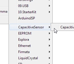
WM8960 Audio Codec
SparkFun has written a library to work with the SparkFun Audio Codec Breakout - WM8960 (Qwiic). You can obtain this library through the Arduino Library Manager by searching for "SparkFun Audio Codec Breakout WM8960". Find the one written by SparkFun Electronics and install the latest version. Users who prefer to manually install the library can get it from the GitHub Repository or download the .ZIP by clicking the button below:
ESP32-A2DP
Paul Schatzmann has written a library to work with I2S audio and wireless audio (BT) using the ESP32 microcontrollers. To manually install the library, get it from the GitHub Repository or download the .ZIP by clicking the button below:
Arduino Code
Now that we have our libraries installed, we can compile and upload the Arduino code to the ESP32 Thing Plus.
Serial Upload
Below is the Arduino sketch INO for this project. Copy and paste the code below in your Arduino IDE.
SuperHeadphones Arduino Sketch
1 2 3 4 5 6 7 8 9 10 11 12 13 14 15 16 17 18 19 20 21 22 23 24 25 26 27 28 29 30 31 32 33 34 35 36 37 38 39 40 41 42 43 44 45 46 47 48 49 50 51 52 53 54 55 56 57 58 59 60 61 62 63 64 65 66 67 68 69 70 71 72 73 74 75 76 77 78 79 80 81 82 83 84 85 86 87 88 89 90 91 92 93 94 95 96 97 98 99 100 101 102 103 104 105 106 107 108 109 110 111 112 113 114 115 116 117 118 119 120 121 122 123 124 125 126 127 128 129 130 131 132 133 134 135 136 137 138 139 140 141 142 143 144 145 146 147 148 149 150 151 152 153 154 155 156 157 158 159 160 161 162 163 164 165 166 167 168 169 170 171 172 173 174 175 176 177 178 179 180 181 182 183 184 185 186 187 188 189 190 191 192 193 194 195 196 197 198 199 200 201 202 203 204 205 206 207 208 209 210 211 212 213 214 215 216 217 218 219 220 221 222 223 224 225 226 227 228 229 230 231 232 233 234 235 236 237 238 239 240 241 242 243 244 245 246 247 248 249 250 251 252 253 254 255 256 257 258 259 260 261 262 263 264 265 | |
Select your board in the Tools menu (in our case ESP32 Thing Plus) and the correct Port it enumerated on and click "Upload". After uploading the code, open the Serial Monitor or terminal emulator of your choice with the baud rate set to 115200. You should see the following message pop up. And then as you turn the volume potentiometer, the setting value will be printed to the terminal.
 |
If you see the above messages in your terminal, then you should be ready to try out some listening. Put your headphones on and try adjusting the potentiometer. As you turn the knob (clockwise), this will increase the volume level of the microphones.
One way to verify the system is to turn the volume all the way up and gently rub each microphone with your fingertip. You should hear a quiet scratching sound in the corresponding headphone ear speaker.
Note, if you hear a lot of buzzing, it is most likely the USB cable. Try unplugging the USB cable, and powering only from the battery. The battery will be a much quieter power source, and so should not add any noise into the audio signal.
Wireless connection
In addition to the messages sent to the serial terminal, the provided code sets up the ESP32 Thing Plus to be an audio receiver as a bluetooth A2DP Sink.
After powering up your headphones, use your PC or cell phone to find a Bluetooth device named "SuperHeadphones".
-

Connect BT with your PC
-

Connect to BT with your cell phone


Click Connect. Now you can play audio from your PC program or phone app and listen on your superheadphones!
Note, the volume control for this sound source is controlled by adjusting the setting on your computer or cell phone. The knob on the headphones is only used to adjust the volume of the ambient microphones.
Diving deeper
The provided code for this project is a combination of other Arduino example sketches. Review these for further information on how each section of the code works.
-
WM8960 Arduino Library Examples:
-
ESP32-A2DP Arduino Library Examples:
Microphone Selection
Specifications
For this particular project, we needed a microphone with three specific characteristics:
-
) It needed to have a high acoustic overload point (AOP). This would allow the microphones to be located on the outside of the ear-cans, very close to a full-volume acoustic drum set, and still not distort. Our final mic choice has an AOP of 135dB.
-
) It needed to have a large signal to noise ratio (SNR). This means that the microphone will output a cleaner signal with less "hiss" sound during quiet times. Something with at least 60dB or great would work. Our ultimate choice was for a microphone that had 75dB SNR.
-
) It needed decent sensitivity. Something near the range of -35dB would do. Note, when this number gets higher, that means it's more sensitive. Because sensitivity is almost always expressed as a negative number, that means a "smaller" negative number is more sensitive.
To learn more about microphone specifications such as AOP, SNR, sensitivity, please check out this very informative document from InvenSense here:
I tried three other microphones before I found my favorite. Here is a table to show the others options, and how they compare in terms of mic specs.
| Mic | AOP | SNR | Sensitivity | Notes |
|---|---|---|---|---|
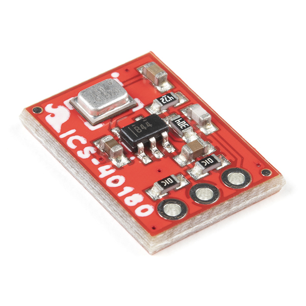
| ICS-40180 | 124dB | 65dB | −38dB | With the onboard op amp gain, this ultimately had too low of an resulting AOP for drums. It clipped a lot when I played loudly. |
| SPH8878LR5H-1 | 134dB | 66dB | -44dB | Again, with the onboard op amp gain, this ultimately had too low of an AOP for drums. It clipped a lot when I played loudly. |
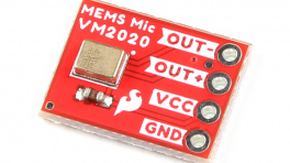
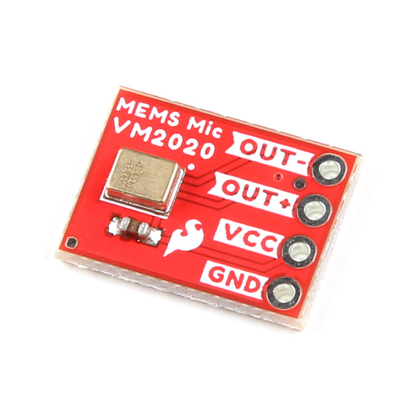
| VM2020 | 149dB | 50dB | -63dB | With such a high AOP, this mic could definitely handle the loud drums without clipping. This was a huge win, and actually, I used these mics for quite a while. But then I started to notice that during quiet times, there was a significant "hiss" in the audio signal. This is because it is, in terms of audio microphones, not very sensitive (-63dB). In order to hear the signal at a decent level, I had to add 60dB to 70dB of gain in the WM8960, which also can add some hiss to the signal. |
| AOM-5035L | 135dB | 75dB | -35dB | The best combination of high AOP, impressive sensitivity and SNR. No clipping and no hiss. This one fits the job! |
Options
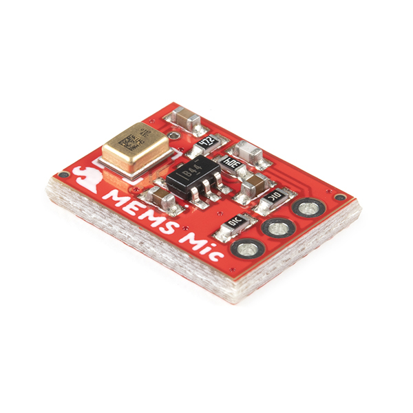
Here are the four microphones we ultimately tested. Note, although for our application, the AOM-5035 was the right choice, you might like to consider trying out some of the other mics and see if they work for your use case. If I were making these for playing piano or any kind of quieter environment, I might go with one of the MEMs.

What's next
The next generation of super headphones might include some additional features. Here are some of my ideas:
Mic Signal Output
With an additional WM8960 codec, I could send a copy of the isolated ambient mics to a line-level output. This would be handy for recording. Especially, if I just want to get an idea down with decent sound quality. The movement of my head (particularly rotationally) plays into the sound, so this is not ideal for recording for a final mix, but super handy for practice recordings.
Advanced Audio Processing
It would be nice to take in the I2S audio from the codec and add some digital effects. For example EQ, compression and/or limiting could be very nice. I also find my carpeted basement to sound slightly tight. It would be killer to add in some reverb!
Additional Mics
I have thought that adding a second set of ambient mics with higher sensitivity could be a nice improvement. Although the current mics (PUI-AOM-5035) do great for loud environments, it is not 100% ideal for use in quieter environments. If you want to capture quieter sound sources (like acoustic instruments such as piano, guitar or even conversation), then a more sensitive microphone is better suited for the job. A more sensitive microphone requires less gain to capture the quieter sounds, and thus produces less noise in those situations.
Mixing the two microphones automatically would be ideal. But this would require a rather uncommon effect on the sensitive mic. You'd have to use an "inverted" noise gate. This would shut down the signal from the sensitive mic when it gets close to its clipping level, and then open up the gate to the high AOP mic at the same time.
It turns out that PUI makes another similar microphone that is 11dB more sensitive, and has a whopping 80dB SNR! See the specs here:
Custom 3D Printed Cans!
Currently, the generic headphones I have hacked are pretty comfy, but I do notice the pressure of the pads on my ears. When I’m drumming, I don’t seem to mind - probably because I’m so focused on playing. But for general listening, I start to become a bit uncomfortable after 30 minutes or so. My ears are pretty long (I guess), and they angle out away from my head, so these headphones are essentially squishing my ears against my skull.
I've already begun the journey to creating some very custom headphones. I think that I should be able to make something that still has a really good seal to block out the loud sounds, but also is super comfy. I’ll probably make some for my kid too, because he needs to take breaks due to the ear-muffs causing some discomfort.
The basic idea I have is to scan in my head, then design some custom fit headphones. Ideally, the cans and internal speaker drivers wouldn't touch my ears at all. Also, the touch points around my ears would have a custom adapter that would apply equal pressure all around.
It has started with a decent scan using photogrammetry. To learn more about this process, check out this wonderful YouTube video by Punished Props Academy:
After following along with that video, and doing a few practice scans, I was able to successfully scan my head.
Then it is only a matter of importing the mesh into Fusion 360 and designing around the model of my head and ears.
Going into detail about how this is all done is beyond the scope of this tutorial, but I thought I'd share some of the photos from the design work that is currently still in progress.
Cheers and happy hacking!


My first print... fresh out of the gray goop!
Troubleshooting Tips
Info
Not working as expected and need help?
If you need technical assistance and more information on a product that is not working as you expected, we recommend heading on over to the SparkFun Technical Assistance page for some initial troubleshooting.
If you can't find what you need there, you'll need a Forum Account to search product forums and post questions.
Resources:
For more resources related to this project, check out the links listed here:
- General
- Arduino Code (ZIP)
- Block Diagram (JPG)
- Wiring Diagram (JPG)
- Mic Circuit (PNG)
- AOM-5035 Microphone Datasheet (PDF)
- App Note on Mic Specs AN-1112-v1.1 (PDF)
- Custom Mother-board PCB
- Schematic (PDF)
- Eagle Files (ZIP)
- Board Dimensions (PNG)
- Board Dimensions (PDF)
- Board Dimensions (DXF)
- Audio Codec
- ESP32 Thing Plus
Looking for more information related to the SuperHeadphones, check out the following IEEE article below!
