Examples
Example 1: Basic Readings
This first example just does some basic measurements. To find Example 1, go to File > Examples > SparkFun 6DoF LSM6DSV16X > example1_basic:
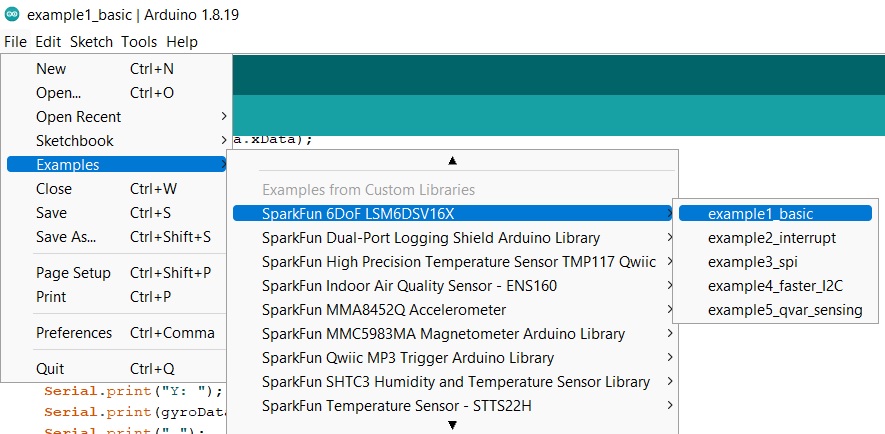
Finding Example 1
Alternatively, you can expand the link below and copy and paste the code into a shiny new Arduino sketch:
Example 1 Arduino Code
/*
  example1-basic

  This example shows the basic settings and functions for retrieving accelerometer
    and gyroscopic data.

  Written by Elias Santistevan @ SparkFun Electronics, May, 2022

    Products:

    SparkFun 6DoF LSM6DSV16X (Qwiic):
        https://www.sparkfun.com/products/21325

    SparkFun Micro 6DoF LSM6DSV16X (Qwiic):
        https://www.sparkfun.com/products/21336

  Repository:
        https://github.com/sparkfun/SparkFun_LSM6DSV16X_Arduino_Library

  SparkFun code, firmware, and software is released under the MIT
    License (http://opensource.org/licenses/MIT).
*/

#include "SparkFun_LSM6DSV16X.h"
#include <Wire.h>

SparkFun_LSM6DSV16X myLSM;

// Structs for X,Y,Z data
sfe_lsm_data_t accelData;
sfe_lsm_data_t gyroData;

void setup()
{

    Wire.begin();

    Serial.begin(115200);
    while (!Serial)
    {
    }

    Serial.println("LSM6DSV16X Example 1 - Basic Readings I2C");

    if (!myLSM.begin())
    {
        Serial.println("Did not begin, check your wiring and/or I2C address!");
        while (1)
            ;
    }

    // Reset the device to default settings. This if helpful is you're doing multiple
    // uploads testing different settings.
    myLSM.deviceReset();

    // Wait for it to finish reseting
    while (!myLSM.getDeviceReset())
    {
        delay(1);
    }

    Serial.println("Board has been Reset.");
    Serial.println("Applying settings.");

    // Accelerometer and Gyroscope registers will not be updated
    // until read.
    myLSM.enableBlockDataUpdate();

    // Set the output data rate and precision of the accelerometer
    myLSM.setAccelDataRate(LSM6DSV16X_ODR_AT_7Hz5);
    myLSM.setAccelFullScale(LSM6DSV16X_16g);

    // Set the output data rate and precision of the gyroscope
    myLSM.setGyroDataRate(LSM6DSV16X_ODR_AT_15Hz);
    myLSM.setGyroFullScale(LSM6DSV16X_2000dps);

    // Enable filter settling.
    myLSM.enableFilterSettling();

    // Turn on the accelerometer's filter and apply settings.
    myLSM.enableAccelLP2Filter();
    myLSM.setAccelLP2Bandwidth(LSM6DSV16X_XL_STRONG);

    // Turn on the gyroscope's filter and apply settings.
    myLSM.enableGyroLP1Filter();
    myLSM.setGyroLP1Bandwidth(LSM6DSV16X_GY_ULTRA_LIGHT);

    Serial.println("Ready.");
}

void loop()
{

    // Check if both gyroscope and accelerometer data is available.
    if (myLSM.checkStatus())
    {
        myLSM.getAccel(&accelData);
        myLSM.getGyro(&gyroData);
        Serial.print("Accelerometer: ");
        Serial.print("X: ");
        Serial.print(accelData.xData);
        Serial.print(" ");
        Serial.print("Y: ");
        Serial.print(accelData.yData);
        Serial.print(" ");
        Serial.print("Z: ");
        Serial.print(accelData.zData);
        Serial.println(" ");
        Serial.print("Gyroscope: ");
        Serial.print("X: ");
        Serial.print(gyroData.xData);
        Serial.print(" ");
        Serial.print("Y: ");
        Serial.print(gyroData.yData);
        Serial.print(" ");
        Serial.print("Z: ");
        Serial.print(gyroData.zData);
        Serial.println(" ");
    }

    delay(100);
}
Make sure you've selected the correct board and port in the Tools menu and then hit the upload button. Once the code has finished uploading, go ahead and open a Serial Monitor. You should see something similar to the following. Note the obvious changes where the sensor was turned upright.
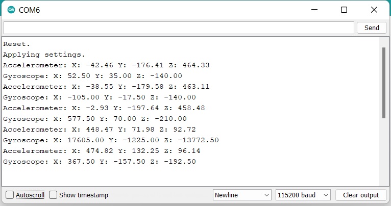
Example 1 Output
Example 2: Interrupt
This example shows the basic settings and functions for retrieving accelerometer data. In addition we're setting the data ready signal to interrupt pin one in an active high configuration and show additional ways in which the interrupts can be configured. To find Example 2, go to File > Examples > SparkFun 6DoF LSM6DSV16X > example2_interrupt.
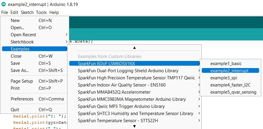
Finding Example 2
Alternatively, you can expand the link below and copy and paste the code into a shiny new Arduino sketch:
Example 2 Arduino Code
/*
  example2-interrupt

  This example shows the basic settings and functions for retrieving accelerometer
    data. In addition we're setting the data ready signal to interrupt pin one in an
    active high configuration and show additional ways in which the interrupts
    can be configured.

  Written by Elias Santistevan @ SparkFun Electronics, May 2022

    Products:

    SparkFun 6DoF LSM6DSV16X (Qwiic):
        https://www.sparkfun.com/products/21325

    SparkFun Micro 6DoF LSM6DSV16X (Qwiic):
        https://www.sparkfun.com/products/21336

  Repository:
        https://github.com/sparkfun/SparkFun_LSM6DSV16X_Arduino_Library

  SparkFun code, firmware, and software is released under the MIT
    License (http://opensource.org/licenses/MIT).
*/

#include "SparkFun_LSM6DSV16X.h"
#include <Wire.h>

// Structs for X,Y,Z data
SparkFun_LSM6DSV16X myLSM;

// Structs for X,Y,Z data
sfe_lsm_data_t accelData;

// Interrupt pin
byte interrupt_pin = 10;

void setup()
{

    // Set the interrupt to INPUT
    pinMode(interrupt_pin, INPUT);

    Serial.begin(115200);
    while (!Serial)
    {
    }

    Serial.println("LSM6DSV16X Example 2 - Interrupts");

    Wire.begin();

    if (!myLSM.begin())
    {
        Serial.println("Did not begin, check your wiring and/or I2C address!");
        while (1)
            ;
    }

    // Reset the device to default settings. This is helpful if you're doing multiple
    // uploads testing different settings.
    myLSM.deviceReset();

    // Wait for it to finish reseting
    while (!myLSM.getDeviceReset())
    {
        delay(1);
    }

    Serial.println("Board has been Reset.");
    Serial.println("Applying settings.");

    // Accelerometer and Gyroscope registers will not be updated
    // until read.
    myLSM.enableBlockDataUpdate();

    // Set the output data rate and precision of the accelerometer
    myLSM.setAccelDataRate(LSM6DSV16X_ODR_AT_7Hz5);
    myLSM.setAccelFullScale(LSM6DSV16X_16g);

    // Turn on the accelerometer's filter and apply settings.
    myLSM.enableAccelLP2Filter();
    myLSM.setAccelLP2Bandwidth(LSM6DSV16X_XL_STRONG);

    // Set the accelerometer's status i.e. the data ready to interrupt one.
    // Commented out just below is the function to send the data ready
    // to interrupt two.

    myLSM.setIntAccelDataReady(LSM_PIN_ONE);
    // myLSM.setIntAccelDataReady(LSM_PIN_TWO);

    // We can just as easily set the gyroscope's data read signal to either interrupt

    // myLSM.setIntGyroDataReady(LSM_PIN_ONE);
    // myLSM.setIntGyroDataReady(LSM_PIN_TWO);

    // Uncommenting the function call below will change interrupt TWO
    // active LOW instead of HIGH.

    // myLSM.setInt2DENActiveLow();

    // This function call will modify which "events" trigger an interrupt. No
    // argument has been given, please refer to the datasheet for more
    // information.

    // Possible values for routing your interrupt include:
    // lsm6dsv16x_pin_int_route_t routeInt;
    // routeInt.drdy_xl = 1;
    // routeInt.drdy_g = 1;
    // routeInt.drdy_g = 1;
    // routeInt.single_tap = 1;
    // routeInt.double_tap = 1;
    // myLSM.setIntRoute(routeInt, LSM_PIN_ONE);

    // This function changes the latching behaviour of the interrupts to pulsed.
    // lsm6dsv16x_data_ready_mode_t mode = LSM6DSV16X_DRDY_PULSED;
    // myLSM.setDataReadyMode();

    Serial.println("Ready.");
}

void loop()
{

    if (digitalRead(interrupt_pin) == HIGH)
    {
        myLSM.getAccel(&accelData);
        Serial.print("Accelerometer: ");
        Serial.print("X: ");
        Serial.print(accelData.xData);
        Serial.print(" ");
        Serial.print("Y: ");
        Serial.print(accelData.yData);
        Serial.print(" ");
        Serial.print("Z: ");
        Serial.print(accelData.zData);
        Serial.println(" ");
    }

    delay(100);
}
Your setup should resemble something like this:
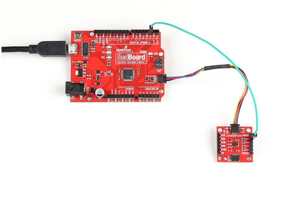
Example 2
Make sure your code matches the pin you've selected as the interrupt pin. Here Pin 2 is wired as the interrupt pin on the RedBoard, so the code was modified to reflect that. Again, make sure you've selected the correct board and port in the Tools menu and then hit the upload button. Once the code has finished uploading, go ahead and open a Serial Monitor. You should see something similar to the following.

Example 2 Output
Example 3: SPI
This example shows the basic settings and functions for retrieving accelerometer and gyroscopic data but using the SPI interface. Everything other than that is identical to the "basic" example. To find Example 3, go to File > Examples > SparkFun 6DoF LSM6DSV16X > example3_spi:
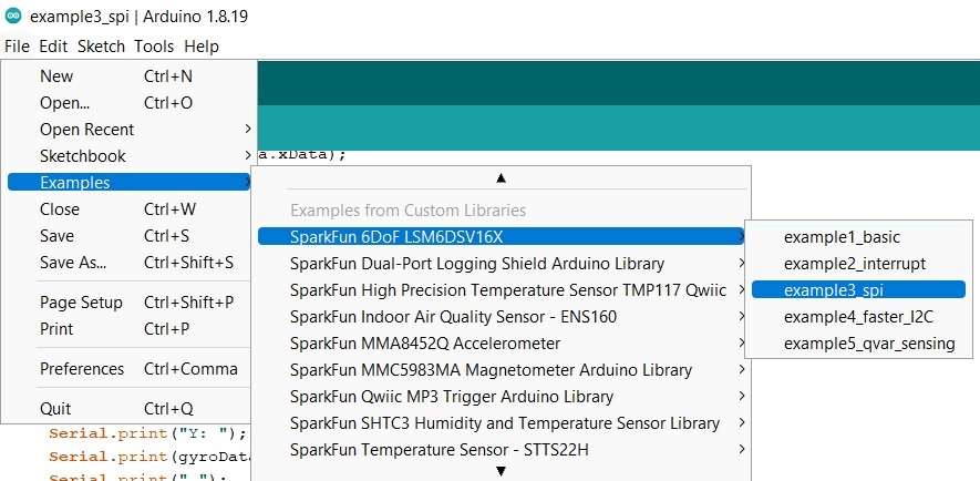
Finding Example 3
Alternatively, you can expand the link below and copy and paste the code into a shiny new Arduino sketch:
Example 3 Arduino Code
/*
  example3-spi

  This example shows the basic settings and functions for retrieving accelerometer
    and gyroscopic data but using the SPI interface. Everything other than that is
    identical to the "basic" example.

  Written by Elias Santistevan @ SparkFun Electronics, May 2022

    Products:

    SparkFun 6DoF LSM6DSV16X (Qwiic):
        https://www.sparkfun.com/products/21325

    SparkFun Micro 6DoF LSM6DSV16X (Qwiic):
        https://www.sparkfun.com/products/21336

  Repository:
        https://github.com/sparkfun/SparkFun_LSM6DSV16X_Arduino_Library

  SparkFun code, firmware, and software is released under the MIT
    License (http://opensource.org/licenses/MIT).
*/

#include "SparkFun_LSM6DSV16X.h"
#include <SPI.h>

// SPI instance class call
SparkFun_LSM6DSV16X_SPI myLSM;

// Structs for X,Y,Z data
sfe_lsm_data_t accelData;
sfe_lsm_data_t gyroData;

// Set your chip select pin according to your setup.
int chipSelect = 10;

void setup()
{

    SPI.begin();

    Serial.begin(115200);
    while (!Serial)
    {
    }

    Serial.println("LSM6DSV16X Example 3 - Basic Readings SPI");

    pinMode(chipSelect, OUTPUT);
    digitalWrite(chipSelect, HIGH);

    if (!myLSM.begin(chipSelect))
    {
        Serial.println("Did not begin, check your wiring and/or I2C address!");
        while (1)
            ;
    }

    // Reset the device to default settings. This if helpful is you're doing multiple
    // uploads testing different settings.
    myLSM.deviceReset();

    // Wait for it to finish reseting
    while (!myLSM.getDeviceReset())
    {
        delay(1);
    }

    Serial.println("Board has been Reset.");
    Serial.println("Applying settings.");

    // Accelerometer and Gyroscope registers will not be updated
    // until read.
    myLSM.enableBlockDataUpdate();

    // Set the output data rate and precision of the accelerometer
    myLSM.setAccelDataRate(LSM6DSV16X_ODR_AT_7Hz5);
    myLSM.setAccelFullScale(LSM6DSV16X_16g);

    // Set the output data rate and precision of the gyroscope
    myLSM.setGyroDataRate(LSM6DSV16X_ODR_AT_15Hz);
    myLSM.setGyroFullScale(LSM6DSV16X_2000dps);

    // Enable filter settling.
    myLSM.enableFilterSettling();

    // Turn on the accelerometer's filter and apply settings.
    myLSM.enableAccelLP2Filter();
    myLSM.setAccelLP2Bandwidth(LSM6DSV16X_XL_STRONG);

    // Turn on the gyroscope's filter and apply settings.
    myLSM.enableGyroLP1Filter();
    myLSM.setGyroLP1Bandwidth(LSM6DSV16X_GY_ULTRA_LIGHT);

    Serial.print("Ready.");
}

void loop()
{

    // Check if both gyroscope and accelerometer data is available.
    if (myLSM.checkStatus())
    {
        myLSM.getAccel(&accelData);
        myLSM.getGyro(&gyroData);
        Serial.print("Accelerometer: ");
        Serial.print("X: ");
        Serial.print(accelData.xData);
        Serial.print(" ");
        Serial.print("Y: ");
        Serial.print(accelData.yData);
        Serial.print(" ");
        Serial.print("Z: ");
        Serial.print(accelData.zData);
        Serial.println(" ");
        Serial.print("Gyroscope: ");
        Serial.print("X: ");
        Serial.print(gyroData.xData);
        Serial.print(" ");
        Serial.print("Y: ");
        Serial.print(gyroData.yData);
        Serial.print(" ");
        Serial.print("Z: ");
        Serial.print(gyroData.zData);
        Serial.println(" ");
    }

    delay(100);
}
The wiring for this example is fairly straight forward, if somewhat ugly. Here's what it looks like:
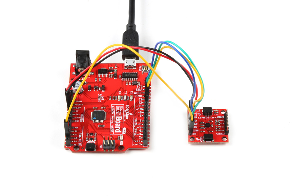
Example 3
And here are the connections:
| Pin Connections | |
|---|---|
| Qwiic Breakout Pin | RedBoard Pin |
| PICO | 11 |
| POCI | 12 |
| SCLK | 13 |
| CS | A4 |
Once you get the correct port and board selected and the code is uploaded, you should see something like the following:
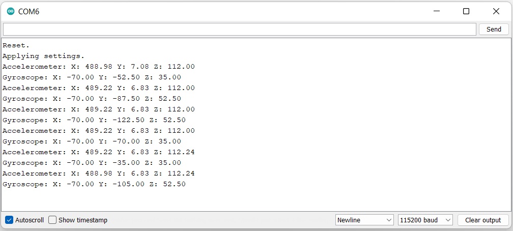
Example 3 Output
Attention
If you are using the SparkFun RedBoard Qwiic and your output only says "Reset. Applying Settings." with no other output, make sure that you have your I/O jumper set correctly. You'll find the 3V3 vs 5V jumper on the front of the RedBoard Qwiic. You'll need to cut the connective trace to 5V and solder the center jumper pad to the 3V3 pad. More information can be found in the RedBoard Qwiic Hookup Guide.
Further Examples
There are a few more examples in the library that get you started with I2C speeds, Qvar, and single/double tap. Feel free to explore and play with these examples to maximize your use of the SparkFun 6DoF - LSM6DSV16X (Qwiic) or SparkFun Micro 6DoF - LSM6DSV16X (Qwiic)!