Getting Started
Note
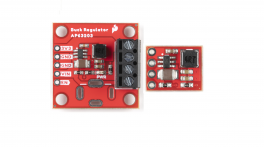
The SparkFun Buck Regulator Breakout - 3.3V (AP3429A) and 1.8V (AP3429A) have similar features to our previous buck regulators (AP63203 & AP63357).
Introduction
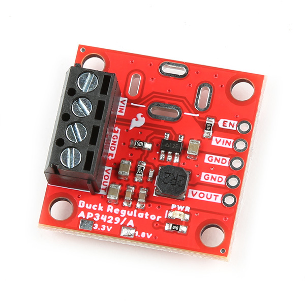
These boards feature the AP3429A from Diodes Inc., a 2A step-down DC-DC converter with an input voltage range of 2.7V to 5.5V. They are configured to provide a regulated 3.3V or 1.8V output, which is controlled by an EN (enable) pin and indicated by a red power LED. A pre-assembled screw terminal and 0.1" spaced PTH pins are available to connect the input and output power of the boards. Additionally, there is the option to solder on a barrel jack for an external power supply. To dissipate excess heat, a 0.5" x 0.6" copper pad is provided to attach a heat sink to the bottom of the board.
-
3.3V Buck Regulator Breakout - AP3429A
SKU: COM-21337
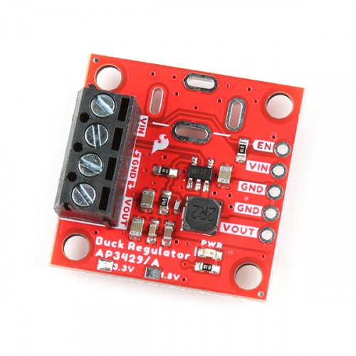
This board provides a regulated 3.3V output with an input voltage range of 3.9V - 5.5V.
 Purchase from SparkFun
-
1.8V Buck Regulator Breakout - AP3429A
SKU: COM-21338

This board provides a regulated 1.8V output with an input voltage range of 2.7V - 5.5V.
 Purchase from SparkFun
Required Materials
To get started, users will need a few items. Now some users may already have a few of these items, feel free to modify your cart accordingly.
- SparkFun Buck Regulator Breakout - 3.3V (AP3429A)
- Heat Sink - Used to help dissipate excess heat
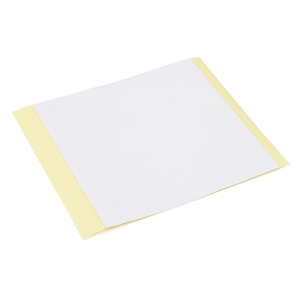
- Thermal Tape - To attach a heat sink to the board
- Power Supply
-
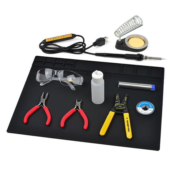
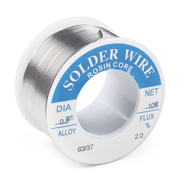
Soldering Tools (1)
- Check out the beginner tool kit below; otherwise, click here for a full selection of our available soldering tools.
-
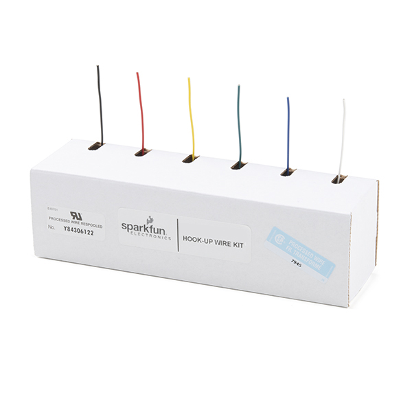
Hookup Wire - May be used to connect the external power or power output
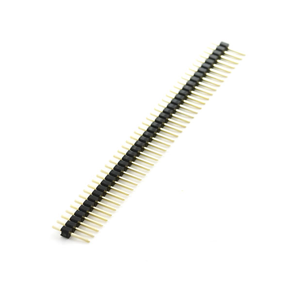
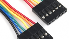
- Headers - May be used to connect the external power or power output
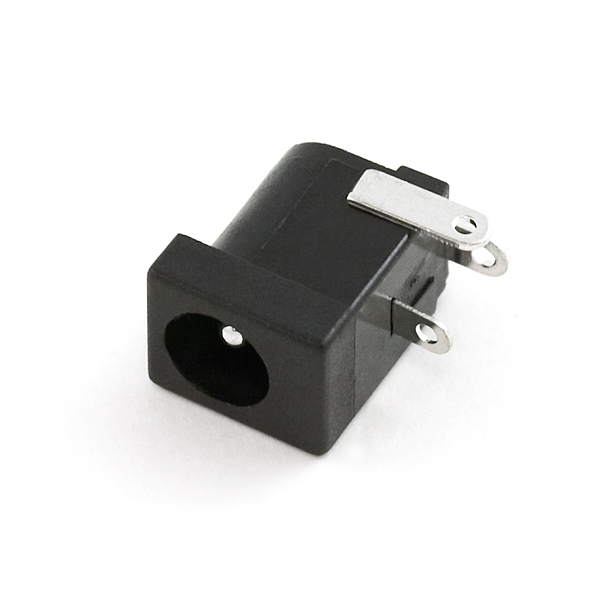
- DC Barrel Jack Adapter
- Small Flathead Screw Driver
-
3.3V Buck Regulator Breakout - (AP3429A)
COM-21337

-
1.8V Buck Regulator Breakout - (AP3429A)
COM-21338
-
Heatsink - 13.20 x 12.10 mm (Copper)
PRT-18704
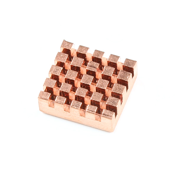
Fits both boards
Thermal tape is included
-
Thermal Tape 4x4" Square
PRT-17054
-
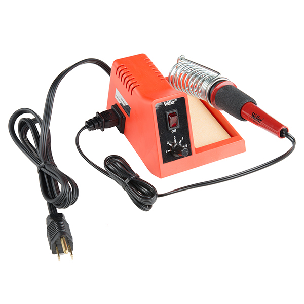
SparkFun Beginner Tool Kit
TOL-14681
New to soldering?
Check out our Through-Hole Soldering Tutorial for a quick introduction!
-
Hook-Up Wire - Assortment (Solid Core, 22 AWG)
PRT-11367
-
Break Away Headers - Straight
PRT-00116
-
DC Barrel Power Jack/Connector
PRT-00119
-
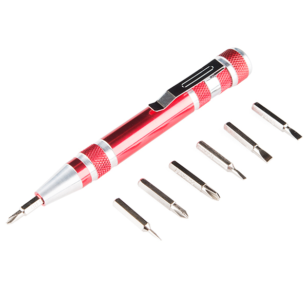
Pocket Screwdriver Set
TOL-12891

Jumper Modification
New to jumper pads?
Check out our Jumper Pads and PCB Traces Tutorial for a quick introduction!

To modify the jumper, users will need soldering equipment and/or a hobby knife.
Battery Options
If users would like to power their board with a battery, we recommend the following options from our catalog.
-
Panasonic Alkaline Battery - AA
PRT-15201
-
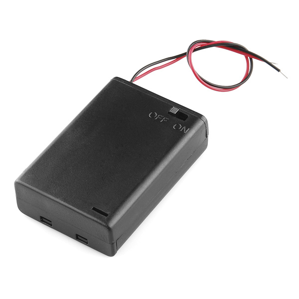
Battery Holder 3xAA with Cover and Switch - Bare Wire
PRT-10891
-
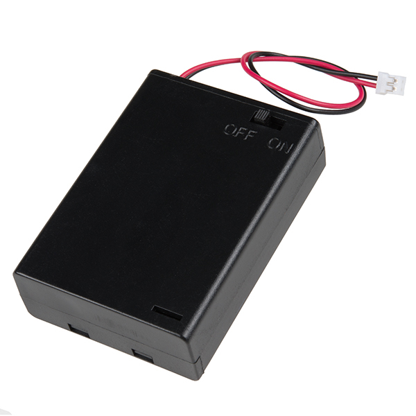
Battery Holder 3xAA with Cover and Switch - JST Connector
PRT-14188
-
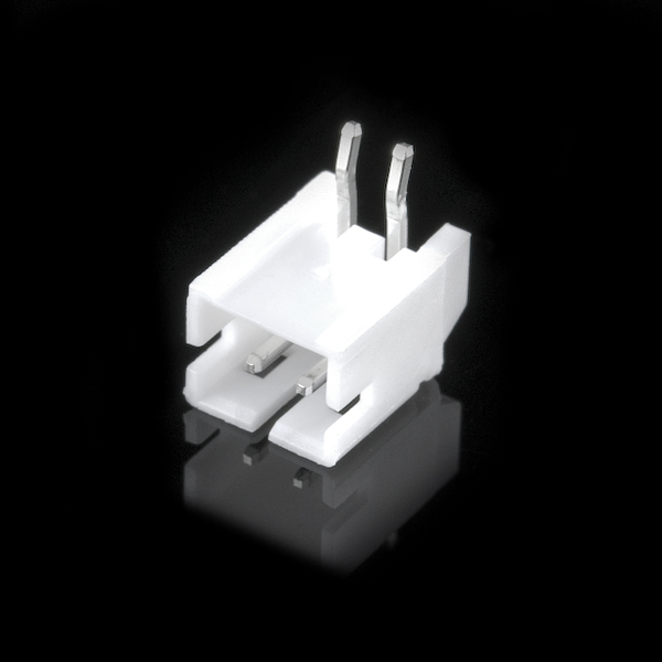
JST Right-Angle Connector - Through-Hole 2-Pin
PRT-09749
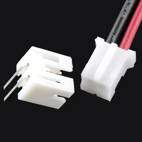
-
JST Jumper 2 Wire Assembly
PRT-09914
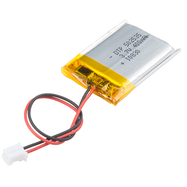
-
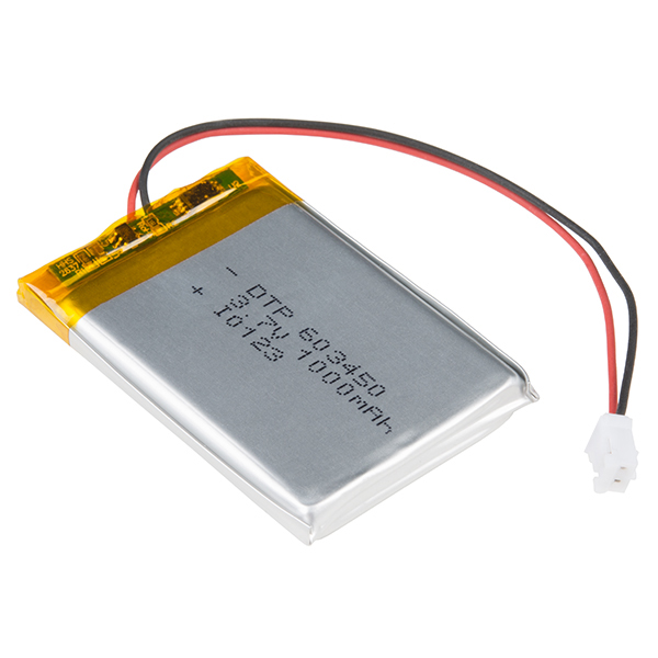
Lithium Ion Battery - 400mAh
PRT-13857
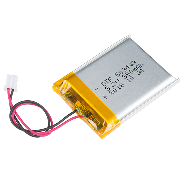
-
Lithium Ion Battery - 850mAh
PRT-13854
-
Lithium Ion Battery - 1Ah
PRT-13813
-
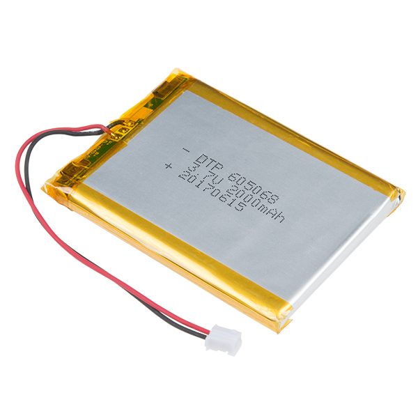
Lithium Ion Battery - 2Ah
PRT-13855
Suggested Reading
Below, are a few tutorials that may help users familiarize themselves with various aspects of this product:

Hardware Overview
Board Dimensions
The board dimensions are illustrated in the drawing below; the listed measurements are in inches.

Board dimensions (PDF) for the AP3429A Buck Regulator breakout boards, in inches.
Need more measurements?
For more information about the board's dimensions, users can download the eagle files for the board. These files can be opened in Eagle and additional measurements can be made with the dimensions tool.
Eagle - Free Download!
Eagle is a CAD program for electronics that is free to use for hobbyists and students. However, it does require an account registration to utilize the software.
 Dimensions Tool
This video from Autodesk demonstrates how to utilize the dimensions tool in Eagle, to include additional measurements:

Power
Users are provided with PTH to connect their external power supply, the output voltage from the board, and the EN power control pin for the buck regulator. The AP3429A buck regulator has an input voltage range is 2.7V to 5.5V. Each board has a different regulated output voltage (1.8V or 3.3V) and input voltage range. (These are step-down DC/DC converters and cannot step-up or boost the voltage output.)

The power connections on the AP3429A Buck Regulator Breakout boards.
Below, is a general summary of the circuitry on the board:
VIN- Power supply input- 1.8V Buck Regulator: 2.7V to 5.5V
- 3.3V Buck Regulator: 3.9V to 5.5V
EN- Enables the power output of the board- Has an input voltage range up to 5.5V
- Must be pulled
HIGHabove 1.5V to enable the power output. Otherwise, if pulledLOWbelow 0.4V, the device shuts down.
VOUT- Regulated 1.8V or 3.3V output (up to 2A)GND- The common ground or the 0V reference for the board
Info
For more details, users can reference the schematic and the datasheets of the individual components in the power circuitry.
Maximum Load Current
While the IC is rated up to 2A, we were able to squeeze a little extra juice for a maximum load of ~2.2A. Anything near 2.4A, the board will start to struggle and automatically shut down.
Disclaimer: We don't recommend that users expect to be able to load the boards with a maximum 2.2A, as we are not sure how this may affect the lifespan of the board. We just want users to know that they may have an extra margin of safety on their peak load.
Quiescent Current Draw
Users should expect a nominal quiescent current draw of ~90µA from the board. For a lower quiescent current, users can disable the power output and/or modify the board by removing the pull-up resistor on the EN pin.
-
Measured Values
Input
Voltage (V)Iq (µA)
Power DisabledIq (µA)
Power Enabled1.8V 3.3V 1.8V 3.3V 5.0 49.34 49.58 85.15 97.48 4.5 44.60 44.81 83.32 96.00 4.2 41.51 41.71 82.64 95.27 3.9 --- 38.70 --- 95.03 3.7 36.60 36.76 81.88 94.87 3.3 32.70 32.84 81.23 338.12 3.0 29.82 N/A 80.59 N/A 2.7 27.06 N/A 79.58 N/A The values in the table above, were measured with a Power Profiler Kit II and averaged over a 10s period.
-
Pull-Up Resistor Modification

Pull-up resistor on the AP3429A Buck Regulator Breakout boards. Danger
Modifying a board to remove the pull-up resistor, requires advanced soldering skills. Users should not attempt this modification unless it is absolutely, necessary and they are confident in their skills because the board can be permanently damaged.
Power Connections
There are several options available for users to connect power to and from their AP3429A buck regulator breakout board.
| Input Options | Output Power | Enable Pin |
|---|---|---|
|
|
|
PTH Pins
Five PTH pins are provided for an external power supply, the output voltage from the board, and the EN power control pin. The holes are spaced 0.1", to be compatible with headers and breadboards.

The PTH power pins on the AP3429A Buck Regulator Breakout boards.
Screw Terminals
A screw terminal is provided for users, as a non-permanent solution, to easily connect wires to the board.
Compatible Wire Sizes
The screw terminal is compatible with wire sizes from 26AWG to 16AWG.

The screw terminal on the AP3429A Buck Regulator Breakout boards.
Barrel Jack
PTH (slots) are provided for users to add a barrel jack connector to the top or bottom of the board. This provides users with an alternative method to connect a power supply to their board.
Barrel Jack Size
Our recommended barrel jack connector is a 5.5mm barrel jack.
-

The plated slots for a barrel jack connector on the top side of the AP3429A Buck Regulator Breakout boards. -

The plated slots for a barrel jack connector on the bottom side of the AP3429A Buck Regulator Breakout boards.
Power LED
The red, power (PWR) LED will light up when the switching power output is enabled. However, the LED can be disabled for low-power applications by cutting the jumper.

The PWR status LED indicator for the AP3429A Buck Regulator Breakout boards.
Power Control
There is an enable pin (EN) to control the output voltage (i.e. on/off), with a typical threshold voltage of 1.5V and a range up to 5.5V
- Users should pull the
ENpin high (above 1.5V) to enable the switching power output and pull the pin low (below 0.4V) to disable it.- Users can connect the
ENpin toVINto override the UVLO threshold.
- Users can connect the
Default Configuration
On our boards, the EN pin is pulled HIGH and the power output from the board is enabled by default.

Enable pin on the AP3429A Buck Regulator Breakout boards.
AP3429A
The AP3429A from Diodes Incorporated, is a 2A DC-DC buck converter with a wide input voltage range of 2.7V to 5.5V. Under a no-load condition, the quiescent current is 90µA; and when disabled, the device shutdown supply current is less than 1µA.
-
Features:
- VIN: 2.7V to 5.5V
- VOUT: 0.6V to VIN
- 2A Continuous Output Current
- 90µA No-Load Quiescent Current
- 1MHz Switching Frequency
- Protection Circuitry
- Undervoltage Lockout (UVLO)
- Input Overvoltage Protection
- Over Current Protection
- Cycle-by-Cycle Peak Current Limit
- Thermal Shutdown
-

AP3429A chip on the AP3429A Buck Regulator Breakout boards.
Info
For more details, please refer to the AP3429A datasheet and application note.
Power Efficiency
Users should expect a power efficiency close to the chart presented in the datasheet (i.e. ~80% with smaller loads and up to +90% with larger loads). It should be noted that the efficiency varies with the load current and cooling.

Circuit Protection
The AP3429A features the following circuit protections:
We have found the undervoltage lockout to trigger ~2.7V for the 1.8V breakout and ~3.9V for the 3.3V breakout board.
- If the peak current is higher than the current limit threshold, it will enter cycle-by-cycle current limit mode.
- If short is detected, when the feedback voltage (VFB) drops under 0.3V, the AP3429 will turn off power output until the
VINorENis cycled again to release it.- Once VFB rises over 0.3V, the AP3429A automatically recovers to normal operation.
- Output: When
VOUTexceeds 120% of the regulation level, the output power will be disabled untilVINorENis cycled. - Input: When the input voltage is near 6.25V, the IC will shut down until the input voltage drops back down below 6V.
Output Voltage Configuration
The output voltage from the AP3429A, is determined by the voltage divider on the feedback loop, as discussed in the application note.
Application Note
While the application note only lists the AP3428 buck converter, Diodes Incorporated has assured us that it is still applicable to the AP3429A.
Where, R1 and R2 are the resistors in the feedback loop:

Example circuit for the AP3429A.
Output Voltage Indicator
Since it would be difficult to differentiate the voltage output based on the small SMD parts, we provide a simple indicator for the configured output voltage of each board.
-

The output voltage indicator for the 3.3V Buck Regulator Breakout. -

The output voltage indicator for the 1.8V Buck Regulator Breakout.
Heat Sink Pad
A 0.5" x 0.6" platted copper pad is provided on the back of the boards, where users can add a heat sink to dissipate excess heat generated by the AP3429A. The pad can accommodate the copper heatsink in our catalog.
Thermal Shutdown Temperature
The AP329A has a 160°C (320°F) thermal shutdown temperature. The AP3429A will restart automatically when the junction temperature decreases to +130°C.

Heat sink pad on the back of the AP3429A Buck Regulator Breakout boards.
Thermal Characteristics
Below are charts depicting the thermal performance of the AP3429A Buck Regulator Breakout boards that users should expect. These values were measured at 200mA steps for input voltages between 4 - 5.5V.


Jumper
Never modified a jumper before?
Check out our Jumper Pads and PCB Traces tutorial for a quick introduction!
There is a jumper on the back of the board that can be used to easily modify a hardware connection on the board.
- PWR - This jumper can be used to remove power to the
PWRLED.

The LED jumper on the back of the AP3429A Buck Regulator Breakout boards.
Hardware Assembly
Headers
New to soldering?
If you have never soldered before or need a quick refresher, check out our How to Solder: Through-Hole Soldering guide.
The pins for the SparkFun AP3429A Buck Regulator Breakout boards are broken out to 0.1"-spaced pins on the outer edges of the board. When selecting headers, be sure you are aware of the functionality and board orientation required.

Soldering headers to the AP3429A Buck Regulator Breakout boards.
Jumper the Enable Pin
On the AP3429A Buck Regulator Breakout board, users can short the VIN and EN pins. This will allow users to bypass the undervoltage threshold and force the power output to be enabled.
Hookup Wire
New to soldering?
If you have never soldered before or need a quick refresher, check out our How to Solder: Through-Hole Soldering guide.
Users can also solder their wire connections directly to the pins of the AP3429A Buck Regulator breakout boards. When planning out the connections, be sure you are aware of the functionality required.
Danger
With higher current applications, users should ensure the wires can handle the current load. (i.e. A 32AWG wire probably won't be able to handle 2A)

Soldering wires to the AP3429A Buck Regulator Breakout boards.
Barrel Jack PTH
New to soldering?
If you have never soldered before or need a quick refresher, check out our How to Solder: Through-Hole Soldering guide.
A barrel jack connector can be added to the AP3429A Buck Regulator breakout boards. The plated through-hole slots allow the barrel jack connector to be oriented on the top or bottom of the board.
-

Soldering a barrel jack connector onto the top of the AP3429A Buck Regulator Breakout board. -

Soldering a barrel jack connector onto the bottom of the AP3429A Buck Regulator Breakout board.
Screw Terminals
A screw terminal is a great non-permanent solution, to connect the board. To use the screw terminals, simply insert the correct wires into the screw terminal opening and tighten the screw with a small flathead screwdriver for a firm connection.

Connecting a wire to the AP3429A Buck Regulator Breakout Board's' screw terminal.
Battery Power
Unlike our previous buck converter breakouts, the output voltage for these AP3429A buck converters is low enough to be supplied by batteries. Users can connect batteries directly to the board, utilizing the screw terminals or PTH pins.
2-Pin JST Connector
Another option is to solder on a 2-pin JST right-angle connector. Make sure to note the polarity of the connections to the JST connector before attaching it to the board.

Soldering a 2-pin JST right-angle connector to the AP3429A Buck Regulator Breakout boards.
This connector is compatible with several of our LiPo batteries and battery packs. Just make sure to select an option that is appropriate for your project.
-

The AP3429A Buck Regulator Breakout board powered by a 3xAA battery pack. -

The AP3429A Buck Regulator Breakout board powered by a 400mA LiPo battery. LiPo Batteries
Utilize a LiPo battery with an undervoltage protection circuit. This will ensure that the buck regulator boards don't damage the battery as its energy is depleted.
Disconnecting Hardware
DO NOT remove batteries by pulling on their wires. Instead, it is recommended that pair of dikes (i.e. diagonal wire cutters), pliers, or tweezers be used to pull on the JST connector housing, to avoid damaging the battery wiring.

Using a pair of dikes to disconnect a battery.
Heat Sink
Tip
With larger heat sinks, we recommend a test fit and attaching it last to avoid conflicts with other parts of the board. For example, the heat sink could block the PTH pins/slots or access to the jumper pad.
To attach a heat sink to the board, users will also need a piece of thermal tape. We recommend the following procedure:
-
Cut out a piece of thermal tape to fit the bottom of the heat sink.
Tip
Covering the entire bottom of the heat sink can insulate the electrical contacts on the board from shorting.
- For a perfect fit, users can place the heat sink over the tape and trace the outline to cut with scissors.
- For a perfect fit, users can also place the heat sink over the tape and cut the outline with a hobby knife.
-
Place the piece of thermal tape on the bottom of the heat sink.
Tip
We recommend peeling off just one side of the backing sheet or release liner to place the thermal tape on the heat sink. Users can then peel the other side off when they are ready to place the heat sink on their board.
-
Attach the heat sink to the board.
- Make sure to make any jumper modifications and/or solder any connections before placing the heat sink on the board.
- Make sure to avoid any electrical contact with the sides of the heat sink.
-

Different heat sinks next to the AP3429A Buck Regulator Breakout board. -

Heat sink attached to the AP3429A Buck Regulator Breakout board.
Troubleshooting Tips
Need Help?
If you need technical assistance or more information on a product that is not working as you expected, we recommend heading on over to the SparkFun Technical Assistance page for some initial troubleshooting.
If you can't find what you need there, the SparkFun Forums is a great place to search product forums and ask questions.
Account Registration Required
If this is your first visit to our forum, you'll need to create a Forum Account to post questions.
Bypass the UVLO
Default Configuration
On our boards, the EN pin is pulled-up to enable the power output from the board by default.
On the Buck Regulator boards, users can short/jumper the VIN and EN pins. This will bypass the undervoltage lockout setting and allow users to provide a lower input voltage. However, it should be noted that because this is a step-down converter and the input voltage should remain higher than the regulated output voltage.
Connecting Batteries
For lower current applications, users can connect a battery as the power source. However, please be aware of the input voltage range for each board and the limitations of utilizing rechargeable batteries. We recommend a 3xAA battery pack and AA alkaline batteries for novice users to avoid technical complications.
Lithium Ion Batteries
While lithium polymer batteries have a nominal voltage of 3.7V, the voltage will vary as it is discharged. These types of batteries often have a range of approximately 3.2V to 4.2V and will be damaged if their voltage exceeds these parameters. Therefore, we recommend that users only connect LiPo batteries with a protection circuit from the manufacturer.
Warning
For example, the 18650 lithium-ion batteries in our catalog don't include a battery protection circuit. If used with the 1.8V buck regulator and left to discharge below 3.2V, the battery would be permanently damaged and rendered useless.
There is no way to recover the battery from this type of damage. (While there are hacks to get the battery working again, its performance will be significantly reduced.)
Info
With an undervoltage threshold of 3.7V, 3.3V buck regulator will not be able to utilize the full capacity of a LiPo battery. The board will be unable to access the last 40-50% of the LiPo battery's charge capacity.
Test Setup
For users who would like to test their buck regulators, this page demonstrates a simple load test.
Note
Users who wish to test the maximum parameters of their board should consider using a professional/benchtop DC electric load tester, instead of the variable load kit.
Required Hardware
To test the buck regulator boards, users will need the following hardware:
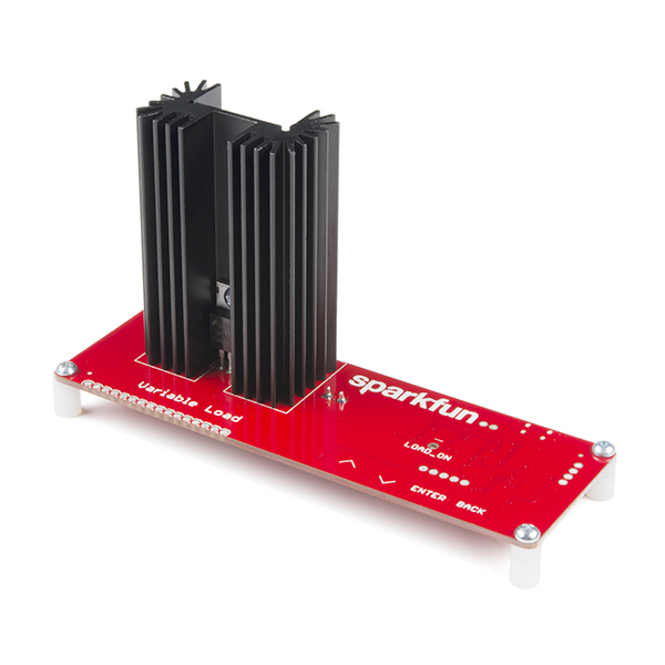
- DC Electric Load Tester
- We are using the SparkFun Variable Load Kit
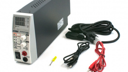
- Power Supply
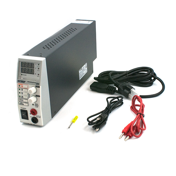
- Use a benchtop-style power supply where you can configure the output voltage and see the current draw when loaded.
- We are using the 80W DC Power Supply (retired product)
Hardware Setup
For this test, the hardware was setup up as follows:
- Power was supplied to the buck regulator through the soldered barrel jack.
- The output power from the buck regulator was connected to the variable load kit, through the screw terminal.
- No heat sink was attached to the buck regulator.

Setup for a basic load test on the AP3429A Buck Regulator Breakout boards.
Test
To perform the test, the power supply was set to provide 4.5V at up to 4A. Meanwhile, the SparkFun variable load kit was configured to draw 0.5A.

A load test being performed on the AP3429A Buck Regulator Breakout board.
Although it is a little hard to see in the picture, the power supply is providing 4.45V with a 430mA current draw to the buck regulator. The variable load kit is drawing 0.49A with the 3.34V output voltage from the buck regulator.
Resources
Product Resources
-
Composite (Both Boards)
- Product Category
- Board Dimensions
- Component Documentation
- Design Files:
- Hardware Repo
-
3.3V Buck Regulator Breakout - (AP3429A)
- Product Page
- Design Files:
-
1.8V Buck Regulator Breakout - (AP3429A)
- Product Page
- Design Files:
Additional Resources
🏭 Manufacturer's Resources
Diodes Incorporated also provides great resources for the AP3429A Buck Regulator:
