Hardware Overview
Board Dimensions
The board dimensions are illustrated in the drawing below; the listed measurements are in inches.

Board dimensions (PDF) for the AP3429A Buck Regulator breakout boards, in inches.
Need more measurements?
For more information about the board's dimensions, users can download the eagle files for the board. These files can be opened in Eagle and additional measurements can be made with the dimensions tool.
Eagle - Free Download!
Eagle is a CAD program for electronics that is free to use for hobbyists and students. However, it does require an account registration to utilize the software.
 Dimensions Tool
This video from Autodesk demonstrates how to utilize the dimensions tool in Eagle, to include additional measurements:

Power
Users are provided with PTH to connect their external power supply, the output voltage from the board, and the EN power control pin for the buck regulator. The AP3429A buck regulator has an input voltage range is 2.7V to 5.5V. Each board has a different regulated output voltage (1.8V or 3.3V) and input voltage range. (These are step-down DC/DC converters and cannot step-up or boost the voltage output.)
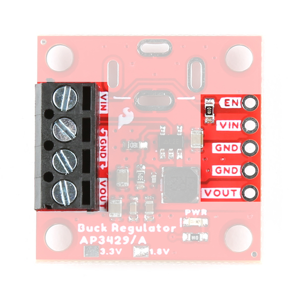
The power connections on the AP3429A Buck Regulator Breakout boards.
Below, is a general summary of the circuitry on the board:
VIN- Power supply input- 1.8V Buck Regulator: 2.7V to 5.5V
- 3.3V Buck Regulator: 3.9V to 5.5V
EN- Enables the power output of the board- Has an input voltage range up to 5.5V
- Must be pulled
HIGHabove 1.5V to enable the power output. Otherwise, if pulledLOWbelow 0.4V, the device shuts down.
VOUT- Regulated 1.8V or 3.3V output (up to 2A)GND- The common ground or the 0V reference for the board
Info
For more details, users can reference the schematic and the datasheets of the individual components in the power circuitry.
Maximum Load Current
While the IC is rated up to 2A, we were able to squeeze a little extra juice for a maximum load of ~2.2A. Anything near 2.4A, the board will start to struggle and automatically shut down.
Disclaimer: We don't recommend that users expect to be able to load the boards with a maximum 2.2A, as we are not sure how this may affect the lifespan of the board. We just want users to know that they may have an extra margin of safety on their peak load.
Quiescent Current Draw
Users should expect a nominal quiescent current draw of ~90µA from the board. For a lower quiescent current, users can disable the power output and/or modify the board by removing the pull-up resistor on the EN pin.
-
Measured Values
Input
Voltage (V)Iq (µA)
Power DisabledIq (µA)
Power Enabled1.8V 3.3V 1.8V 3.3V 5.0 49.34 49.58 85.15 97.48 4.5 44.60 44.81 83.32 96.00 4.2 41.51 41.71 82.64 95.27 3.9 --- 38.70 --- 95.03 3.7 36.60 36.76 81.88 94.87 3.3 32.70 32.84 81.23 338.12 3.0 29.82 N/A 80.59 N/A 2.7 27.06 N/A 79.58 N/A The values in the table above, were measured with a Power Profiler Kit II and averaged over a 10s period.
-
Pull-Up Resistor Modification
Pull-up resistor on the AP3429A Buck Regulator Breakout boards. Danger
Modifying a board to remove the pull-up resistor, requires advanced soldering skills. Users should not attempt this modification unless it is absolutely, necessary and they are confident in their skills because the board can be permanently damaged.
Power Connections
There are several options available for users to connect power to and from their AP3429A buck regulator breakout board.
| Input Options | Output Power | Enable Pin |
|---|---|---|
|
|
|
PTH Pins
Five PTH pins are provided for an external power supply, the output voltage from the board, and the EN power control pin. The holes are spaced 0.1", to be compatible with headers and breadboards.
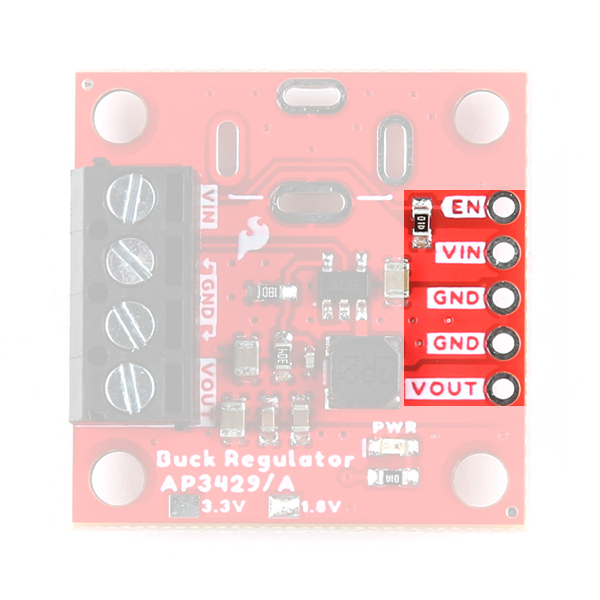
The PTH power pins on the AP3429A Buck Regulator Breakout boards.
Screw Terminals
A screw terminal is provided for users, as a non-permanent solution, to easily connect wires to the board.
Compatible Wire Sizes
The screw terminal is compatible with wire sizes from 26AWG to 16AWG.
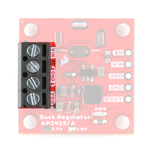
The screw terminal on the AP3429A Buck Regulator Breakout boards.
Barrel Jack
PTH (slots) are provided for users to add a barrel jack connector to the top or bottom of the board. This provides users with an alternative method to connect a power supply to their board.
Barrel Jack Size
Our recommended barrel jack connector is a 5.5mm barrel jack.
-
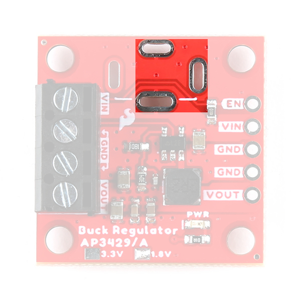
The plated slots for a barrel jack connector on the top side of the AP3429A Buck Regulator Breakout boards. -

The plated slots for a barrel jack connector on the bottom side of the AP3429A Buck Regulator Breakout boards.
Power LED
The red, power (PWR) LED will light up when the switching power output is enabled. However, the LED can be disabled for low-power applications by cutting the jumper.

The PWR status LED indicator for the AP3429A Buck Regulator Breakout boards.
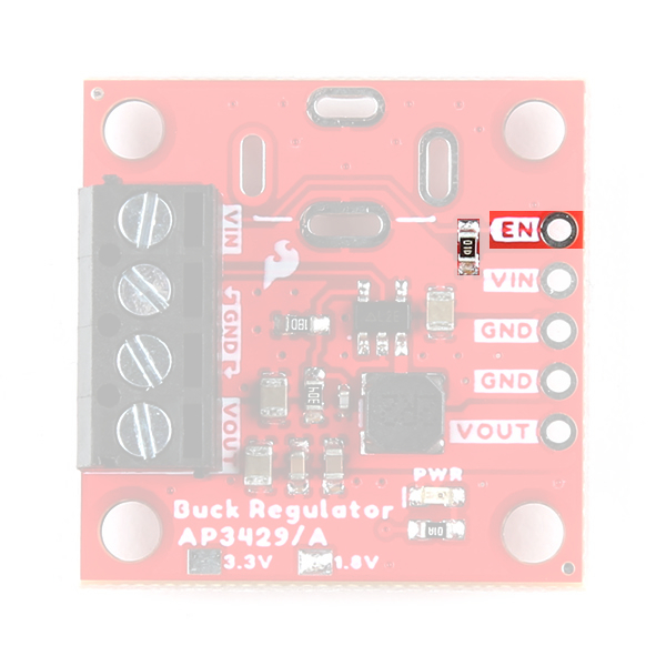
Power Control
There is an enable pin (EN) to control the output voltage (i.e. on/off), with a typical threshold voltage of 1.5V and a range up to 5.5V
- Users should pull the
ENpin high (above 1.5V) to enable the switching power output and pull the pin low (below 0.4V) to disable it.- Users can connect the
ENpin toVINto override the UVLO threshold.
- Users can connect the
Default Configuration
On our boards, the EN pin is pulled HIGH and the power output from the board is enabled by default.
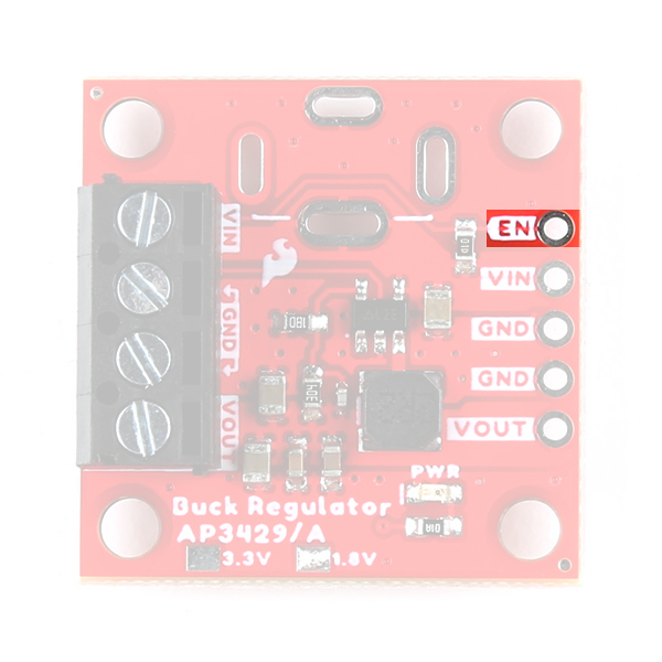
Enable pin on the AP3429A Buck Regulator Breakout boards.
AP3429A
The AP3429A from Diodes Incorporated, is a 2A DC-DC buck converter with a wide input voltage range of 2.7V to 5.5V. Under a no-load condition, the quiescent current is 90µA; and when disabled, the device shutdown supply current is less than 1µA.
-
Features:
- VIN: 2.7V to 5.5V
- VOUT: 0.6V to VIN
- 2A Continuous Output Current
- 90µA No-Load Quiescent Current
- 1MHz Switching Frequency
- Protection Circuitry
- Undervoltage Lockout (UVLO)
- Input Overvoltage Protection
- Over Current Protection
- Cycle-by-Cycle Peak Current Limit
- Thermal Shutdown
-
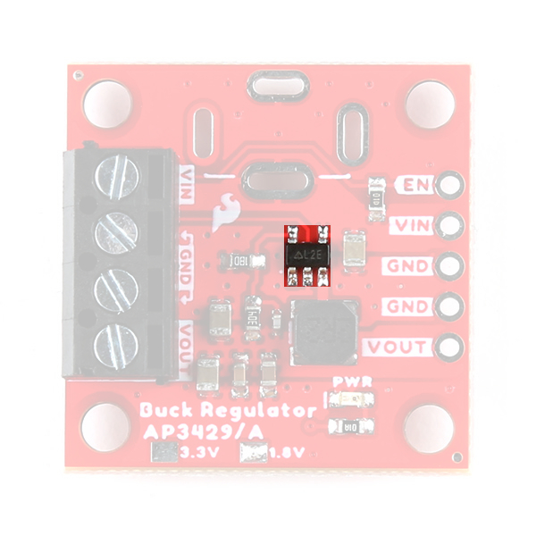
AP3429A chip on the AP3429A Buck Regulator Breakout boards.
Info
For more details, please refer to the AP3429A datasheet and application note.
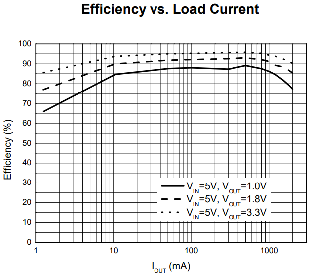
Power Efficiency
Users should expect a power efficiency close to the chart presented in the datasheet (i.e. ~80% with smaller loads and up to +90% with larger loads). It should be noted that the efficiency varies with the load current and cooling.
Circuit Protection
The AP3429A features the following circuit protections:
We have found the undervoltage lockout to trigger ~2.7V for the 1.8V breakout and ~3.9V for the 3.3V breakout board.
- If the peak current is higher than the current limit threshold, it will enter cycle-by-cycle current limit mode.
- If short is detected, when the feedback voltage (VFB) drops under 0.3V, the AP3429 will turn off power output until the
VINorENis cycled again to release it.- Once VFB rises over 0.3V, the AP3429A automatically recovers to normal operation.
- Output: When
VOUTexceeds 120% of the regulation level, the output power will be disabled untilVINorENis cycled. - Input: When the input voltage is near 6.25V, the IC will shut down until the input voltage drops back down below 6V.
Output Voltage Configuration
The output voltage from the AP3429A, is determined by the voltage divider on the feedback loop, as discussed in the application note.
Application Note
While the application note only lists the AP3428 buck converter, Diodes Incorporated has assured us that it is still applicable to the AP3429A.
Where, R1 and R2 are the resistors in the feedback loop:
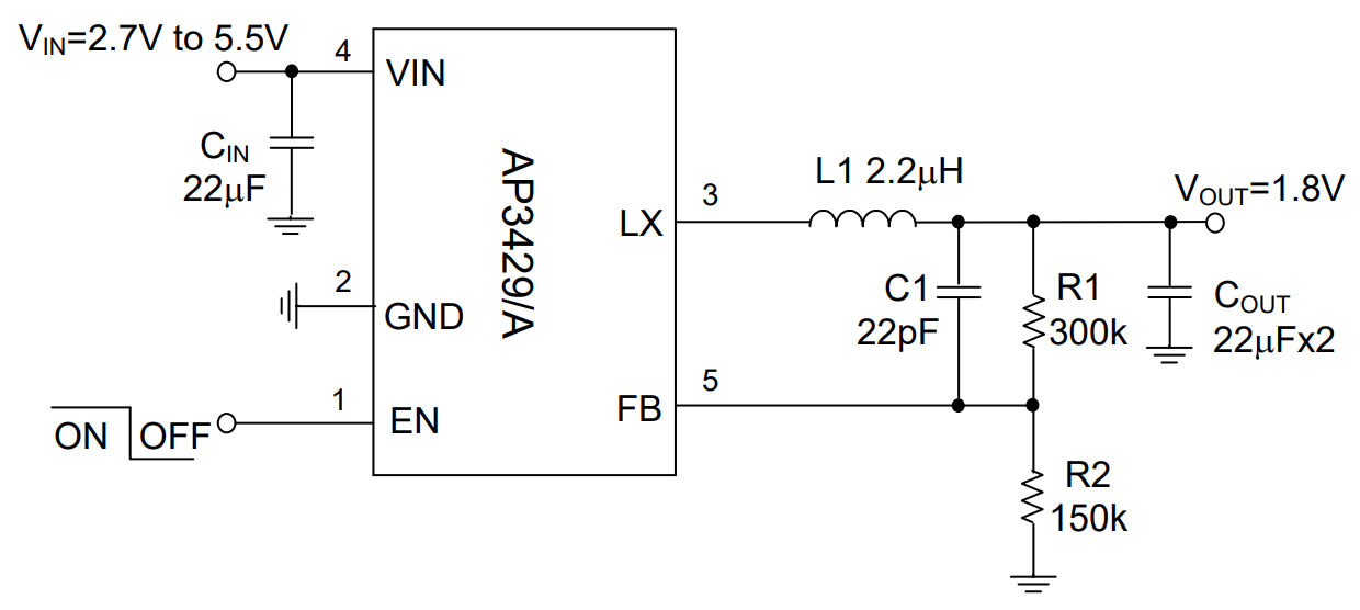
Example circuit for the AP3429A.
Output Voltage Indicator
Since it would be difficult to differentiate the voltage output based on the small SMD parts, we provide a simple indicator for the configured output voltage of each board.
-

The output voltage indicator for the 3.3V Buck Regulator Breakout. -

The output voltage indicator for the 1.8V Buck Regulator Breakout.
Heat Sink Pad
A 0.5" x 0.6" platted copper pad is provided on the back of the boards, where users can add a heat sink to dissipate excess heat generated by the AP3429A. The pad can accommodate the copper heatsink in our catalog.
Thermal Shutdown Temperature
The AP329A has a 160°C (320°F) thermal shutdown temperature. The AP3429A will restart automatically when the junction temperature decreases to +130°C.
Heat sink pad on the back of the AP3429A Buck Regulator Breakout boards.
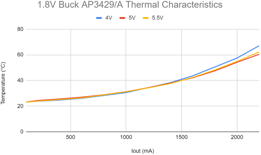
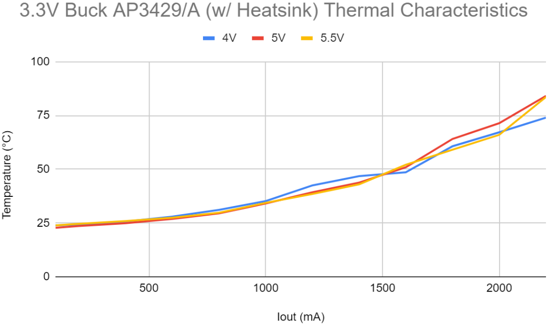
Thermal Characteristics
Below are charts depicting the thermal performance of the AP3429A Buck Regulator Breakout boards that users should expect. These values were measured at 200mA steps for input voltages between 4 - 5.5V.


Jumper
Never modified a jumper before?
Check out our Jumper Pads and PCB Traces tutorial for a quick introduction!

There is a jumper on the back of the board that can be used to easily modify a hardware connection on the board.
- PWR - This jumper can be used to remove power to the
PWRLED.

The LED jumper on the back of the AP3429A Buck Regulator Breakout boards.