Hardware Assembly
Headers
New to soldering?
If you have never soldered before or need a quick refresher, check out our How to Solder: Through-Hole Soldering guide.

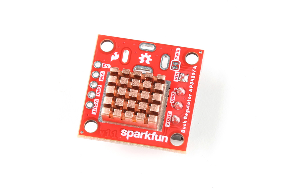
The pins for the SparkFun AP3429A Buck Regulator Breakout boards are broken out to 0.1"-spaced pins on the outer edges of the board. When selecting headers, be sure you are aware of the functionality and board orientation required.

Soldering headers to the AP3429A Buck Regulator Breakout boards.
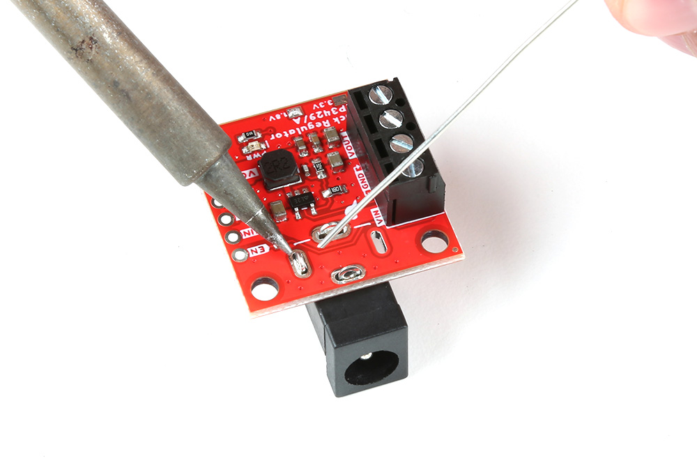
Jumper the Enable Pin
On the AP3429A Buck Regulator Breakout board, users can short the VIN and EN pins. This will allow users to bypass the undervoltage threshold and force the power output to be enabled.
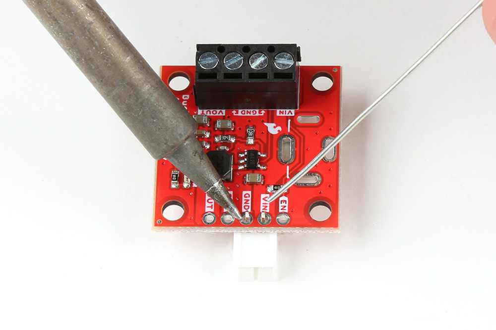
Hookup Wire
New to soldering?
If you have never soldered before or need a quick refresher, check out our How to Solder: Through-Hole Soldering guide.
Users can also solder their wire connections directly to the pins of the AP3429A Buck Regulator breakout boards. When planning out the connections, be sure you are aware of the functionality required.
Danger
With higher current applications, users should ensure the wires can handle the current load. (i.e. A 32AWG wire probably won't be able to handle 2A)

Soldering wires to the AP3429A Buck Regulator Breakout boards.
Barrel Jack PTH
New to soldering?
If you have never soldered before or need a quick refresher, check out our How to Solder: Through-Hole Soldering guide.
A barrel jack connector can be added to the AP3429A Buck Regulator breakout boards. The plated through-hole slots allow the barrel jack connector to be oriented on the top or bottom of the board.
-

Soldering a barrel jack connector onto the top of the AP3429A Buck Regulator Breakout board. -
Soldering a barrel jack connector onto the bottom of the AP3429A Buck Regulator Breakout board.
Screw Terminals
A screw terminal is a great non-permanent solution, to connect the board. To use the screw terminals, simply insert the correct wires into the screw terminal opening and tighten the screw with a small flathead screwdriver for a firm connection.

Connecting a wire to the AP3429A Buck Regulator Breakout Board's' screw terminal.
Battery Power
Unlike our previous buck converter breakouts, the output voltage for these AP3429A buck converters is low enough to be supplied by batteries. Users can connect batteries directly to the board, utilizing the screw terminals or PTH pins.
2-Pin JST Connector
Another option is to solder on a 2-pin JST right-angle connector. Make sure to note the polarity of the connections to the JST connector before attaching it to the board.
Soldering a 2-pin JST right-angle connector to the AP3429A Buck Regulator Breakout boards.
This connector is compatible with several of our LiPo batteries and battery packs. Just make sure to select an option that is appropriate for your project.
-
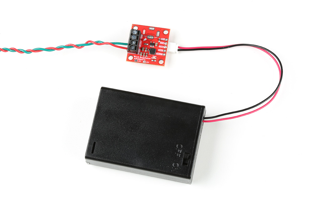
The AP3429A Buck Regulator Breakout board powered by a 3xAA battery pack. -

The AP3429A Buck Regulator Breakout board powered by a 400mA LiPo battery. LiPo Batteries
Utilize a LiPo battery with an undervoltage protection circuit. This will ensure that the buck regulator boards don't damage the battery as its energy is depleted.
Disconnecting Hardware
DO NOT remove batteries by pulling on their wires. Instead, it is recommended that pair of dikes (i.e. diagonal wire cutters), pliers, or tweezers be used to pull on the JST connector housing, to avoid damaging the battery wiring.

Using a pair of dikes to disconnect a battery.
Heat Sink
Tip
With larger heat sinks, we recommend a test fit and attaching it last to avoid conflicts with other parts of the board. For example, the heat sink could block the PTH pins/slots or access to the jumper pad.
To attach a heat sink to the board, users will also need a piece of thermal tape. We recommend the following procedure:
-
Cut out a piece of thermal tape to fit the bottom of the heat sink.
Tip
Covering the entire bottom of the heat sink can insulate the electrical contacts on the board from shorting.
- For a perfect fit, users can place the heat sink over the tape and trace the outline to cut with scissors.
- For a perfect fit, users can also place the heat sink over the tape and cut the outline with a hobby knife.
-
Place the piece of thermal tape on the bottom of the heat sink.
Tip
We recommend peeling off just one side of the backing sheet or release liner to place the thermal tape on the heat sink. Users can then peel the other side off when they are ready to place the heat sink on their board.
-
Attach the heat sink to the board.
- Make sure to make any jumper modifications and/or solder any connections before placing the heat sink on the board.
- Make sure to avoid any electrical contact with the sides of the heat sink.
-
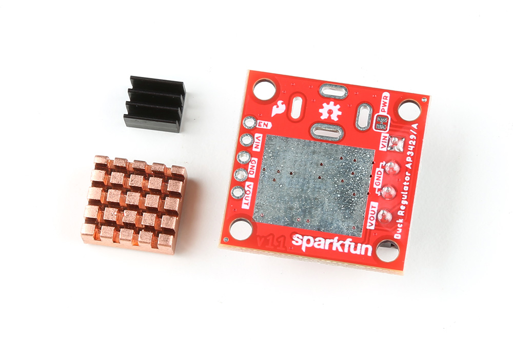
Different heat sinks next to the AP3429A Buck Regulator Breakout board. -
Heat sink attached to the AP3429A Buck Regulator Breakout board.