Load Test
For users who would like to test their buck regulators, this page demonstrates a simple load test on the 5V buck regulator board.
Note
Users who wish to test the maximum parameters of their board will need to consider the thermal and current limitations of the hardware. At minimum:
- A professional/benchtop DC electric load tester should be used instead of the variable load kit.
- Active cooling should be provided to the buck regulator.
Required Hardware
To test the buck regulator boards, users will need the following hardware:
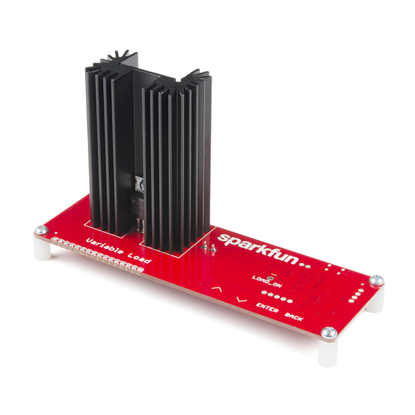
- DC Electric Load Tester
- We are using the SparkFun Variable Load Kit
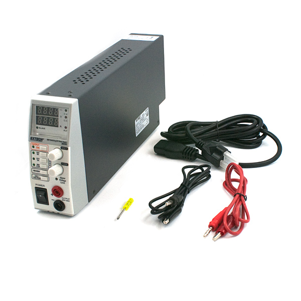
- Power Supply
- Use a benchtop-style power supply where you can configure the output voltage and see the current draw when loaded.
- We are using the 80W DC Power Supply (retired product)
Power Supply - 80W DC Switching ModeTOL-09291 |

SparkFun Variable Load KitKIT-14449 |
Hardware Setup
For this test, the hardware was setup up as follows:
- Power was supplied to the buck regulator through the soldered barrel jack.
- The output power from the buck regulator was connected to the variable load kit, through the screw terminal.
- Power was enabled using a jumper on the headers, soldered to the
VINandENPTH pins. - No heat sink was attached to the buck regulator.
Test
To perform the test, the power supply was set to provide 6.08V at up to 4A. Meanwhile, the SparkFun variable load kit was configured to draw 1A(1).
- For current draws over 1.5A, users should include a heat sink; and active cooling for loads over 2.5A.
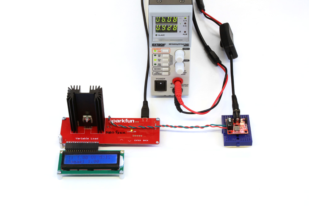
Setup for a basic load test on the 5V Buck Regulator (AP63357DV).
Although it is a little hard to see in the picture, the power supply is providing 6.08V with a 928mA current draw to the buck regulator. The variable load kit is drawing 1A with the 5.11V output voltage from the buck regulator.