-
SparkFun Digi XBee® Explorer USB-C
SKU: WRL-22043
-
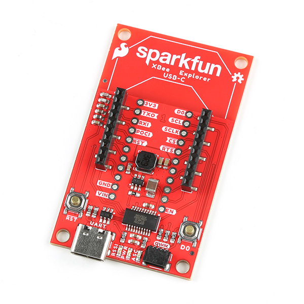
Unleash the power of XBee modules with the next-gen SparkFun Digi XBee® Explorer USB-C! This compact, easy-to-use adapter is the perfect bridge between your computer and any Digi XBee module, making prototyping and development a breeze. Whether you're a seasoned IoT architect or just starting your wireless journey, the XBee Explorer USB-C empowers you to bring your ideas to life. The XBee Explorer USB-C makes it possible to build sensor networks for remote monitoring, control devices wirelessly from your PC, prototype real-time data acquisition systems, and more! This board gives you access to the pin functionality of the XBee, including a single USB-C connector for UART communication, a Qwiic connector for I2C-capable sensors and peripheries, and Reset and D0 buttons.
Purchase from SparkFun
Required Materials
To follow along with this tutorial, you will need the following materials. You may not need everything though depending on what you have. Add it to your cart, read through the guide, and adjust the cart as necessary.
-
SparkFun Digi XBee® Explorer USB-C
WRL-22043 -
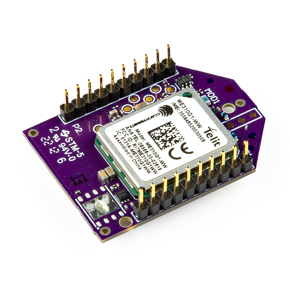
Digi XBee 3 Low-Power LTE-M/NB-IoT, GNSS, no SIM
WRL-22329 -
USB 3.1 Cable A to C - 3 Foot
CAB-14743
Suggested Reading
As a more professionally oriented product, we will skip over the more fundamental tutorials (i.e. Ohm's Law and What is Electricity?). However, below are a few tutorials that may help users familiarize themselves with various aspects of the board.
The SparkFun Digi XBee® Explorer USB-C Board takes advantage of the Qwiic connect system. We recommend familiarizing yourself with the Logic Levels and I2C tutorials. Click on the banner above to learn more about Qwiic products.
Hardware Overview
Digi XBee Smart Modem Socket
We've kept the Digi XBee socket consistent with the Digi XBee pinout, so this breakout board is backwards compatible. In order to take full advantage of this board, we recommend one of the newer Digi XBee boards. The Digi XBee 3 Low-Power LTE-M/NB-IoT, GNSS, no SIM is a great bet.

XBeeSocket
Power
The USB-C connector on the board provides power and is used to communicate with the Digi XBee board via UART. Input VCC range is between 3.3V-5.5V.

USB-C
Buck Converter - AP63203
The AP63203 is a 2A, synchronous buck converter with a wide input voltage range that fully integrates a 125mΩ high-side power MOSFET and a 68mΩ lowside power MOSFET to provide high-efficiency step-down DC/DC conversion. VIN range is 3.8V-5.5V. Output is 2A max.

AP63203 Buck Converter
USB to UART Bridge
The FT231XS translates data between your computer and the Digi XBee. This is one of our favorite chips because it supports all computer platforms and it's easy to work with. If this is the first FTDI chip you've ever connected to your computer (it probably won't be your last), there is some driver installation to get out of the way. We've written a tutorial detailing How to Install FTDI Drivers tutorial.

FT231XS USB to UART Bridge
Qwiic Connector
The Qwiic connector on the SparkFun Digi XBee® Explorer USB-C Board provides power and I2C connectivity to Qwiic breakout boards. Note that I2C functionality is not enabled by default.

Qwiic Connector
LEDs
There are a number of LEDs on the board:

LEDs
PWR
This LED lights up when power is provided to the board.
ASC
This LED on the development board blinks when the Digi XBee is registered to the cellular network.
| Blink | Timing | Meaning |
|---|---|---|
| On | Solid | Not joined to a mobile network |
| Double Blink | ½ second | The last TCP/UDP/SMS attempt failed. If the LED has this pattern, you may need to check DI (Remote Manager Indicator) or CI (Protocol/Connection Indication) for the cause of the error. |
| Single blink | 1 Second | Normal Operation |
RSSI
This LED is the Received Signal Strength Indicator. When configured, it reflects the received signal strength.
RSSI PWM The RSSI/PWM output is enabled continuously, unlike other Digi XBee products where the output is enabled for a short period of time after each received transmission. If running on the XBIB development board, DIO10 is connected to the RSSI LEDs, which may be interpreted as follows:
| PWM duty cycle | Number of LEDs turned on | Received signal strength (dBm) |
|---|---|---|
| 79.39% or more | 3 | 83 dBm or higher |
| 62.42% to 79.39% | 2 | -93 to -83 dBm |
| 45.45% to 62.42% | 1 | -103 to -93 dBm |
| Less than 45.45% | 0 | Less than -103 dBm, or no cellular network connection |
GPIO
We've broken out the Digi XBee pins to plated through holes on either side of the board.

GPIO
Buttons
There are two buttons on the board - D0 and Reset. The Reset button allows the user to reset the running program; the D0 button is connected to GPIO to be used as the user sees fit.

D0 and Reset Buttons
Jumpers
Never modified a jumper before?
Check out our Jumper Pads and PCB Traces tutorial for a quick introduction!

I2C Jumper
The I2C jumper pulls the SDA and SCL pins to VDD (normally 3.3V) through two 2.2K Ohm resistors. If you have multiple Qwiic devices on the same bus you may want to disable these by opening the jumper (assuming they are also operating at 3.3V logic).

I2C Jumpers
LED Jumper
If power consumption is an issue (or if you just don't like the LEDs), cut the respective jumper to sever power to the LED.
- PLED: Red
- ALED: Blue
- RSSI: Yellow

LED Jumpers
Shield Jumper
For most applications, the single point grounding of the Direct USB or UART at the USB-C connector is sufficient. However, should you run into problems with EMI/EMC, we've provided a jumper that allows you to disconnect the connector from ground.

Shield Jumper
Board Dimensions
The SparkFun Digi XBee® Explorer USB-C Board dimensions are illustrated in the drawing below; the listed measurements are in inches.

Board Dimensions
Need more measurements?
For more information about the board's dimensions, users can download the Eagle files for the board. These files can be opened in Eagle and additional measurements can be made with the dimensions tool.
Eagle - Free Download!
Eagle is a CAD program for electronics that is free to use for hobbyists and students. However, it does require an account registration to utilize the software.
 Dimensions Tool
This video from Autodesk demonstrates how to utilize the dimensions tool in Eagle, to include additional measurements:
Hardware Assembly
Note the white silkscreen on the Shield PCB - this will help orient your Digi XBee as you're plugging it in. Make sure to match up the Digi XBee's two diagonal edges with the two diagonal lines on the PCB.

Digi XBee unit being plugged into the SparkFun Digi XBee® Explorer USB-C
Software Setup
We have a number of tutorials detailing how to work with Digi XBees and their associated software. In particular, XCTU is free software provided by Digi (the manufacturer of XBee), that provides a quick and easy way to configure and manage Digi XBees as well as test Digi XBee networks.
If you haven't worked with XCTU before, head on over to our Exploring XBees and XCTU tutorial to get set up.
 |
|---|
| Exploring XBees and XCTU tutorial |
You might also check out this XBee WiFi Hookup Guide if your project includes WiFi!
 |
|---|
| XBee WiFi Hookup Guide |
Troubleshooting Tips
Note
Not working as expected and need help?
If you need technical assistance and more information on a product that is not working as you expected, we recommend heading on over to the SparkFun Technical Assistance page for some initial troubleshooting.
If you don't find what you need there, the SparkFun Forums are a great place to find and ask for help. If this is your first visit, you'll need to create a Forum Account to search product forums and post questions.
Resources:
For more resources related to the SparkFun Digi XBee® Explorer USB-C, check out the links listed here:
Or check out other Digi XBee Projects for inspiration:
 Be All That You Can XBee |
 Wireless RC Robot with Arduino and XBees |
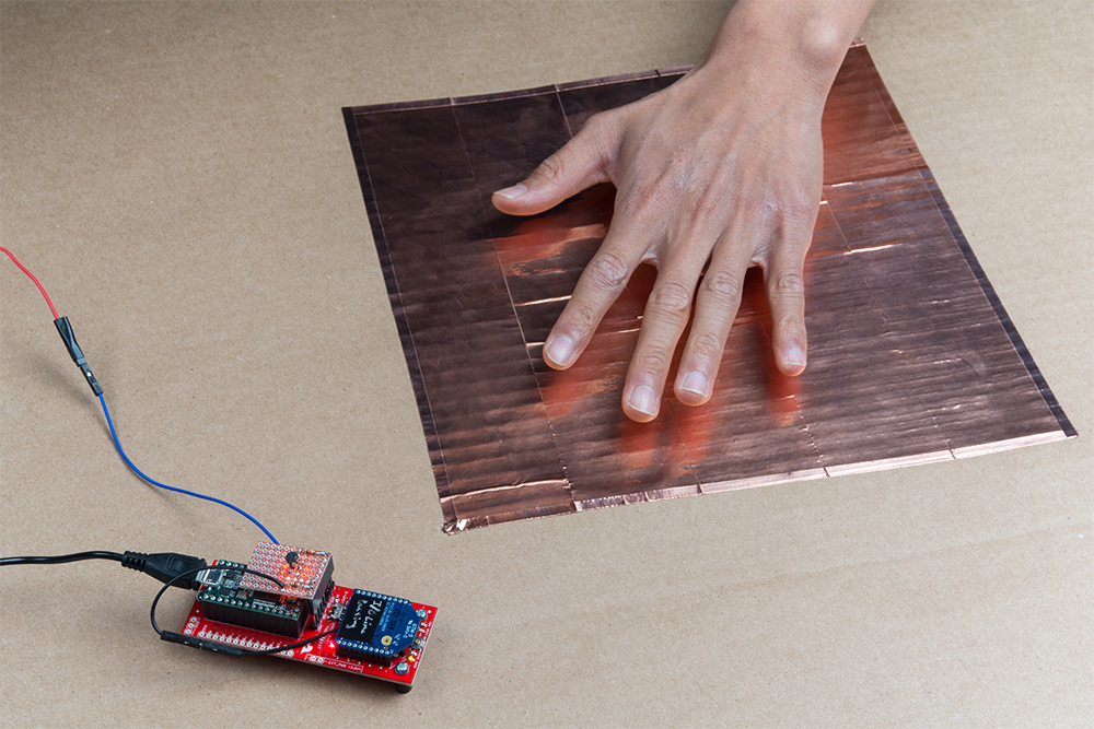 Enginursday: Prototype Capacitive Touch Dance Floor with a Teensy and XBees |
 Wireless Gesture-Controlled Robot |