Hardware Overview
ESP32 PICO Mini
At the core of the SparkFun ESP32 Qwiic Pro Mini is the ESP32-PICO-MINI-02-N8R2 variant which includes 8MB Flash and 2MB PSRAM. There are two CPU cores that can be individually controlled, and the CPU clock frequency is adjustable from 80 MHz to 240 MHz. The chip also has a low-power coprocessor that can be used instead of the CPU to save power while performing tasks that do not require much computing power, such as monitoring of peripherals. For more information, refer to the datasheet.

ESP32 PICO Mini
Power
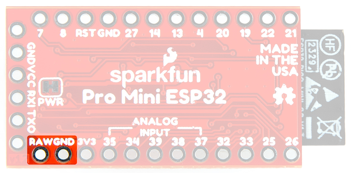
Power is typically supplied via the VCC/GND pins using a USB to Serial adapter. Alternatively, external or portable power can be provided via the GND/RAW pins along the GPIO edge. Note: The AP2112K has a max input voltage of 6V.
The serial programming pins at the edge of the board are FTDI compatible and works best with our CH340 USB to Serial breakout. To utilize the GND/RAW pins along the GPIO edge, we recommend soldering the JST Right-Angle Connector - Through-Hole 2-Pin.
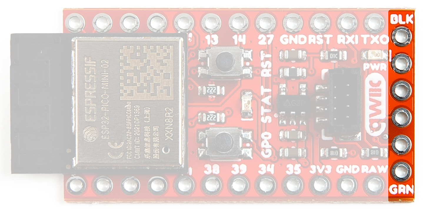
Serial Programming Pins
Power Plated Through Holes
Voltage Regulator - AP2112K
The AP2112K Voltage Regulator ensures that the appropriate voltage is provided to the various components of the board. The AP2112K has a max input voltage of 6V.
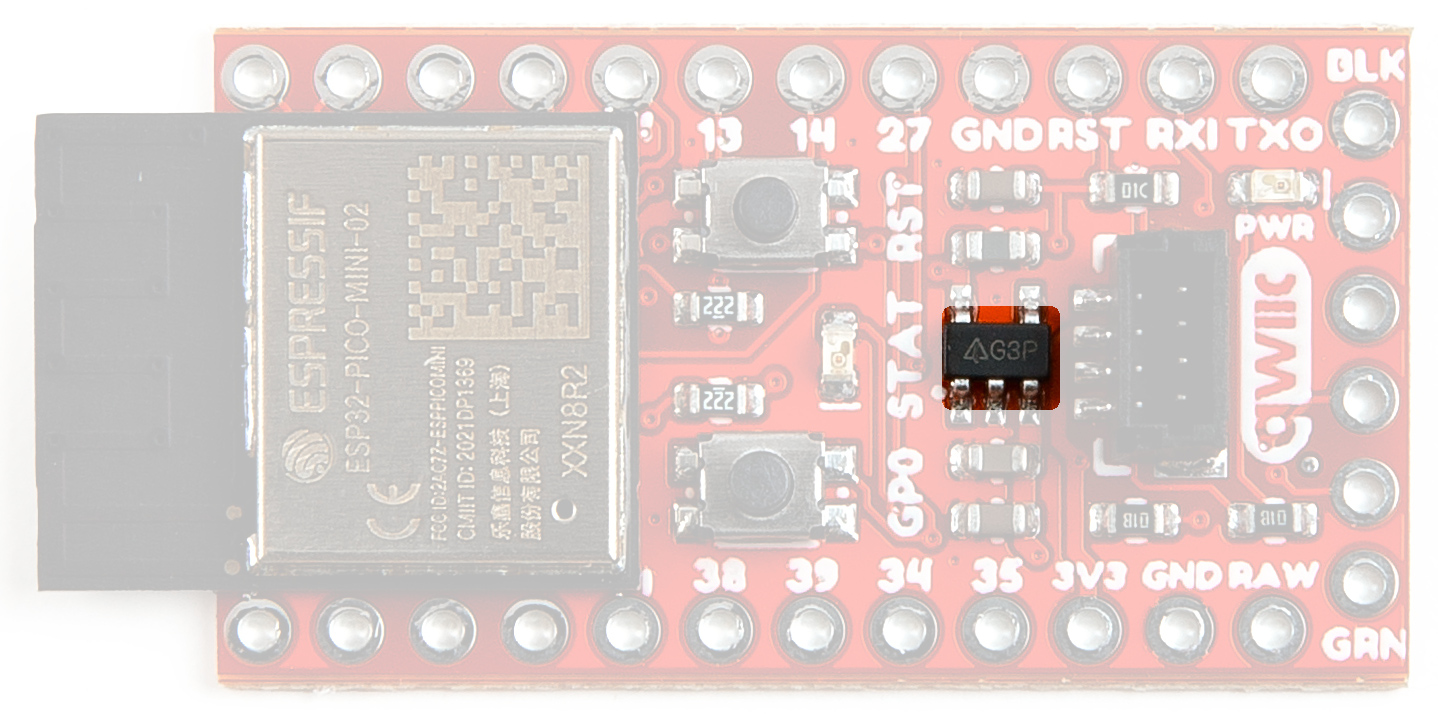
Voltage Regulator - AP2112K
Qwiic connector
The board includes a Qwiic Connector for use with our vast array of Qwiic sensors. The I2C data and clock lines are tied to 2.2kΩ pull-up resistors.
Note that we've mounted the Qwiic Connector vertically to prevent the occlusion of soldering and/or using the GPIO.
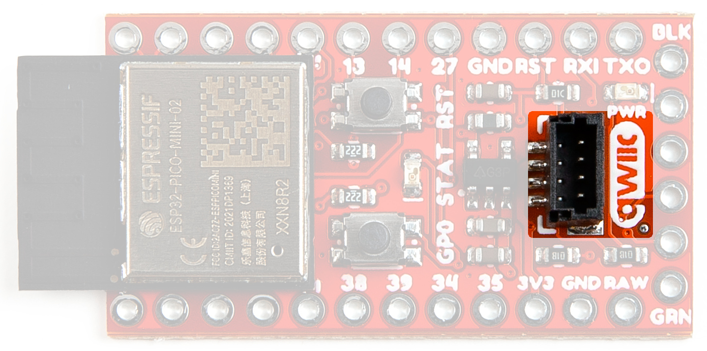
Qwiic connector
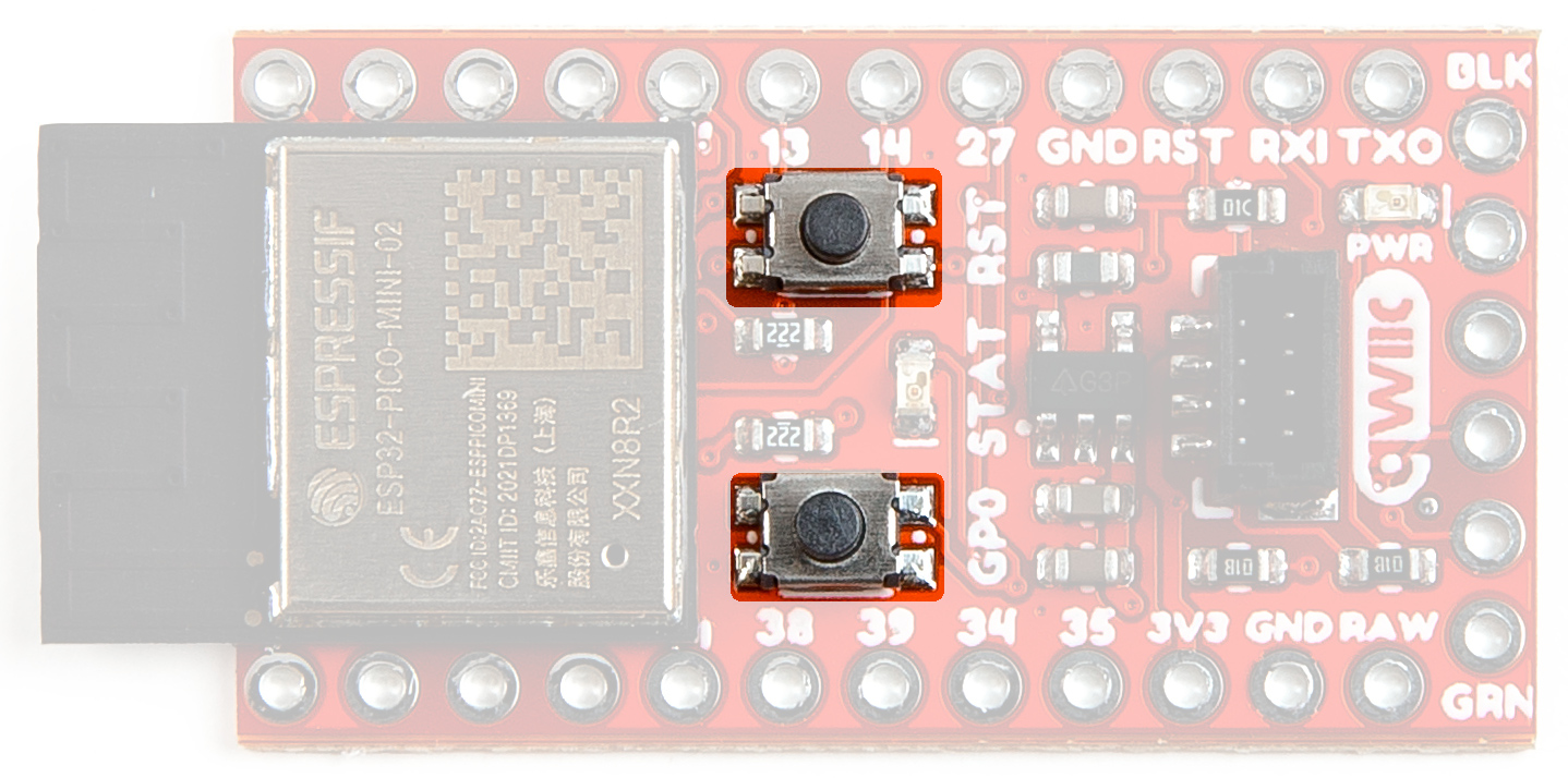
Buttons
There are two buttons on the board - Reset and Boot. The reset (RST) button allows users to reset the program running on the module without unplugging the board. The Boot Button allows the user to manually put the board into Bootloader Mode. To enter bootloader, hold the Boot button down when the ESP32 resets or powers on. These buttons are intentionally next to each other to make it a single finger rolling movement.
Buttons
LEDs
Two LEDs - Power(Red) and STAT(Blue) - show the user that power has been appropriately supplied to the board and the status of the data transfer.

Power and Status LEDs
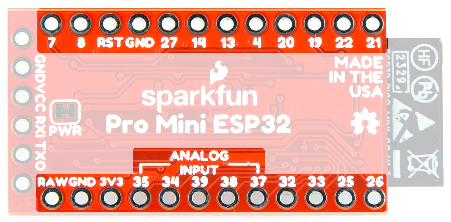
GPIO
The PTH pins are compatible with older Pro Minis. There are a few analog input only pins. They are labeled clearly.
GPIO
Jumpers
Never modified a jumper before?
Check out our Jumper Pads and PCB Traces tutorial for a quick introduction!

Power Jumper
If you have concerns about power consumption, need to run dark, or really just don't like LEDs, you can cut this jumper to disable the red PWR LED on the front of the board.

Power Jumper
Board Dimensions
The board dimensions are illustrated in the drawing below; the listed measurements are in inches.

ESP32 Qwiic Pro Mini Board Dimensions
Need more measurements?
For more information about the board's dimensions, users can download the KiCad files for the board. These files can be opened in KiCad and additional measurements can be made with the dimensions tool.
KiCAD - Free Download!
KiCAD is a CAD program for electronics that is free to use for hobbyists and students. However, it does require an account registration to utilize the software.