Examples
The Arduino Library for the SparkFun 6DoF BMI270 (Qwiic) comes with a slew of examples to get you going. Here we'll just look at a few.
Attention
The BMI270 chip requires an 8kb file to be flashed to memory on the controller. Make sure that whatever controlling board you use, it has enough space.
Example 1: Basic Readings
This first example just does some basic measurements. To find Example 1, go to File > Examples > SparkFun BMI270 Arduino Library > Example01_BasicReadingsI2C:

Finding Example 1
Alternatively, you can expand the link below and copy and paste the code into a shiny new Arduino sketch:
Example 1 Arduino Code
#include <Wire.h>
#include "SparkFun_BMI270_Arduino_Library.h"

// Create a new sensor object
BMI270 imu;

// I2C address selection
uint8_t i2cAddress = BMI2_I2C_PRIM_ADDR; // 0x68
//uint8_t i2cAddress = BMI2_I2C_SEC_ADDR; // 0x69

void setup()
{
    // Start serial
    Serial.begin(115200);
    Serial.println("BMI270 Example 1 - Basic Readings I2C");

    // Initialize the I2C library
    Wire.begin();

    // Check if sensor is connected and initialize
    // Address is optional (defaults to 0x68)
    while(imu.beginI2C(i2cAddress) != BMI2_OK)
    {
        // Not connected, inform user
        Serial.println("Error: BMI270 not connected, check wiring and I2C address!");

        // Wait a bit to see if connection is established
        delay(1000);
    }

    Serial.println("BMI270 connected!");
}

void loop()
{
    // Get measurements from the sensor. This must be called before accessing
    // the sensor data, otherwise it will never update
    imu.getSensorData();

    // Print acceleration data
    Serial.print("Acceleration in g's");
    Serial.print("\t");
    Serial.print("X: ");
    Serial.print(imu.data.accelX, 3);
    Serial.print("\t");
    Serial.print("Y: ");
    Serial.print(imu.data.accelY, 3);
    Serial.print("\t");
    Serial.print("Z: ");
    Serial.print(imu.data.accelZ, 3);

    Serial.print("\t");

    // Print rotation data
    Serial.print("Rotation in deg/sec");
    Serial.print("\t");
    Serial.print("X: ");
    Serial.print(imu.data.gyroX, 3);
    Serial.print("\t");
    Serial.print("Y: ");
    Serial.print(imu.data.gyroY, 3);
    Serial.print("\t");
    Serial.print("Z: ");
    Serial.println(imu.data.gyroZ, 3);

    // Print 50x per second
    delay(20);
}
Make sure you've selected the correct board and port in the Tools menu and then hit the upload button. Once the code has finished uploading, go ahead and open a Serial Monitor. You should see something similar to the following.
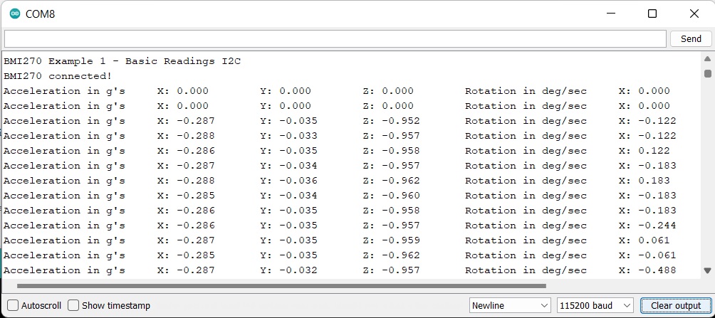
Example 1 Output
Example 6: Calibration to NVM
This example does some basic calibration of the BMI270 and then allows you to write those calibrations to non volatile memory. To find Example 6, go to File > Examples > SparkFun BMI270 Arduino Library > Example06_CalibrationNVM.
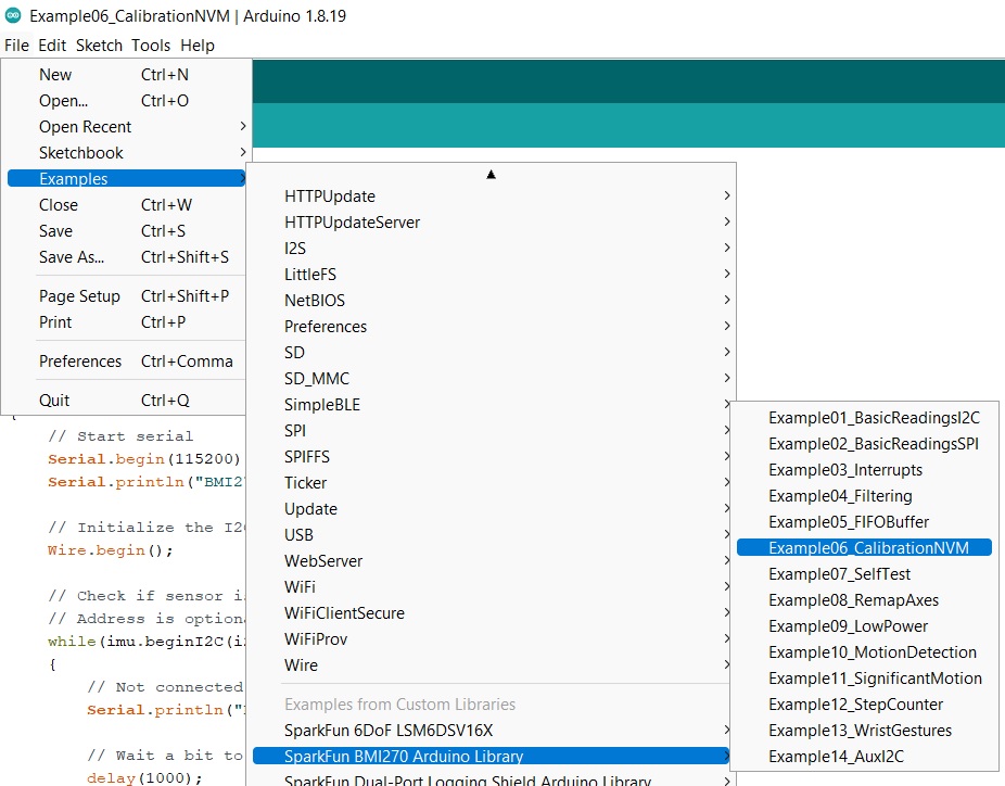
Finding Example 6
Alternatively, you can expand the link below and copy and paste the code into a shiny new Arduino sketch:
Example 6 Arduino Code
#include <Wire.h>
#include "SparkFun_BMI270_Arduino_Library.h"

// Create a new sensor object
BMI270 imu;

// I2C address selection
uint8_t i2cAddress = BMI2_I2C_PRIM_ADDR; // 0x68
//uint8_t i2cAddress = BMI2_I2C_SEC_ADDR; // 0x69

void setup()
{
    // Start serial
    Serial.begin(115200);
    Serial.println("BMI270 Example 6 - Calibration NVM");

    // Initialize the I2C library
    Wire.begin();

    // Check if sensor is connected and initialize
    // Address is optional (defaults to 0x68)
    while(imu.beginI2C(i2cAddress) != BMI2_OK)
    {
        // Not connected, inform user
        Serial.println("Error: BMI270 not connected, check wiring and I2C address!");

        // Wait a bit to see if connection is established
        delay(1000);
    }

    Serial.println("BMI270 connected!");

    Serial.println("Place the sensor on a flat surface and leave it stationary.");
    Serial.println("Enter any key to begin calibration.");

    // Throw away any previous inputs
    while(Serial.available() != 0) {Serial.read();}
    // Wait for user input
    while(Serial.available() == 0) {}

    Serial.println();
    Serial.println("Average sensor values before calibration:");
    printAverageSensorValues();
    Serial.println();

    // Perform component retrim for the gyroscope. According to the datasheet,
    // the gyroscope has a typical error of 2%, but running the CRT can reduce
    // that error to 0.4%
    Serial.println("Performing component retrimming...");
    imu.performComponentRetrim();

    // Perform offset calibration for both the accelerometer and IMU. This will
    // automatically determine the offset of each axis of each sensor, and
    // that offset will be subtracted from future measurements. Note that the
    // offset resolution is limited for each sensor:
    //
    // Accelerometer offset resolution: 0.0039 g
    // Gyroscope offset resolution: 0.061 deg/sec
    Serial.println("Performing acclerometer offset calibration...");
    imu.performAccelOffsetCalibration(BMI2_GRAVITY_POS_Z);
    Serial.println("Performing gyroscope offset calibration...");
    imu.performGyroOffsetCalibration();

    Serial.println();
    Serial.println("Calibration complete!");
    Serial.println();
    Serial.println("Average sensor values after calibration:");
    printAverageSensorValues();
    Serial.println();

    Serial.println("These calibration values can be stored in the sensor's non-volatile memory (NVM).");
    Serial.println("Would you like to save these values to the NVM? If so, enter 'Y'");

    // Throw away any previous inputs
    while(Serial.available() != 0) {Serial.read();}
    // Wait for user input
    while(Serial.available() == 0) {}

    // Check to see if user wants to save values to NVM
    if(Serial.read() == 'Y')
    {
        Serial.println();
        Serial.println("!!! WARNING !!! WARNING !!! WARNING !!! WARNING !!! WARNING !!!");
        Serial.println();
        Serial.println("The BMI270's NVM only supports 14 write cycles TOTAL!");
        Serial.println("Are you sure you want to save to the NVM? If so, enter 'Y' again");

        // Throw away any previous inputs
        while(Serial.available() != 0) {Serial.read();}
        // Wait for user input
        while(Serial.available() == 0) {}

        // Check to see if user *really* wants to save values to NVM
        if(Serial.read() == 'Y')
        {
            // Save NVM contents
            int8_t err = imu.saveNVM();

            // Check to see if the NVM saved successfully
            if(err == BMI2_OK)
            {
                Serial.println();
                Serial.println("Calibration values have been saved to the NVM!");
            }
            else
            {
                Serial.print("Error saving to NVM, error code: ");
                Serial.println(err);
            }
        }
    }

    Serial.println();
    Serial.println("Example done!");
}

// This helper function samples the sensor several times and prints the average
void printAverageSensorValues()
{
    // Variables to store the sum of each sensor axis
    float accXSum = 0;
    float accYSum = 0;
    float accZSum = 0;

    float gyrXSum = 0;
    float gyrYSum = 0;
    float gyrZSum = 0;

    // Collect 50 measurements at 50Hz
    int numSamples = 50;
    for(int i = 0; i < numSamples; i++)
    {
        // Get measurements from the sensor
        imu.getSensorData();

        // Add this measurement to the running total
        accXSum += imu.data.accelX;
        accYSum += imu.data.accelY;
        accZSum += imu.data.accelZ;

        gyrXSum += imu.data.gyroX;
        gyrYSum += imu.data.gyroY;
        gyrZSum += imu.data.gyroZ;

        // Wait for next measurement
        delay(20);
    }

    // Print acceleration data
    Serial.print("Acceleration in g's");
    Serial.print("\t");
    Serial.print("X: ");
    Serial.print(accXSum / numSamples, 3);
    Serial.print("\t");
    Serial.print("Y: ");
    Serial.print(accYSum / numSamples, 3);
    Serial.print("\t");
    Serial.print("Z: ");
    Serial.print(accZSum / numSamples, 3);

    Serial.print("\t");

    // Print rotation data
    Serial.print("Rotation in deg/sec");
    Serial.print("\t");
    Serial.print("X: ");
    Serial.print(gyrXSum / numSamples, 3);
    Serial.print("\t");
    Serial.print("Y: ");
    Serial.print(gyrYSum / numSamples, 3);
    Serial.print("\t");
    Serial.print("Z: ");
    Serial.println(gyrZSum / numSamples, 3);
}

void loop()
{
    // Nothing to do here
}
Again, make sure you've selected the correct board and port in the Tools menu and then hit the upload button. Once the code has finished uploading, go ahead and open a Serial Monitor. You should see something similar to the following.
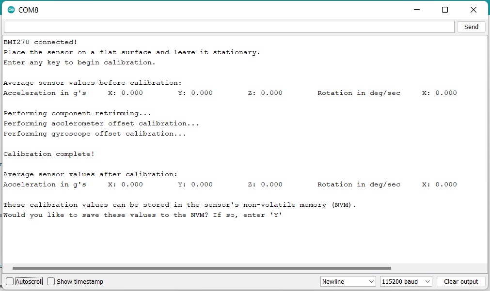
Example 6 Output
Warning
This chip only allows a total of 14 writes. Be mindful of this limit when recalibrating.
Example 12: Step Counter
One of the highlights of the BMI270 chip is that it filters out general noise to give you accurate step counts and the like. This example shows the measurements of the BMI270 for walking, running, and when the breakout board is set back down. To find Example 12, go to File > Examples > SparkFun BMI270 Arduino Library > Example12_StepCounter:
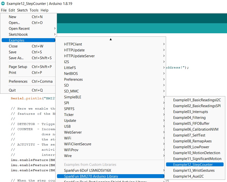
Finding Example 12
Alternatively, you can expand the link below and copy and paste the code into a shiny new Arduino sketch:
Example 12 Arduino Code
#include <Wire.h>
#include "SparkFun_BMI270_Arduino_Library.h"

// Create a new sensor object
BMI270 imu;

// I2C address selection
uint8_t i2cAddress = BMI2_I2C_PRIM_ADDR; // 0x68
//uint8_t i2cAddress = BMI2_I2C_SEC_ADDR; // 0x69

// Pin used for interrupt detection
int interruptPin = 5;

// Flag to know when interrupts occur
volatile bool interruptOccurred = false;

void setup()
{
    // Start serial
    Serial.begin(115200);
    Serial.println("BMI270 Example 12 - Step Counter");

    // Initialize the I2C library
    Wire.begin();

    // Check if sensor is connected and initialize
    // Address is optional (defaults to 0x68)
    while(imu.beginI2C(i2cAddress) != BMI2_OK)
    {
        // Not connected, inform user
        Serial.println("Error: BMI270 not connected, check wiring and I2C address!");

        // Wait a bit to see if connection is established
        delay(1000);
    }

    Serial.println("BMI270 connected!");

    // Here we enable the step detector, counter, and activity recognition
    // features of the BMI270; any combination of these is supported.
    //
    // DETECTOR - Triggers an interrupt whenever a step is detected
    // COUNTER  - Increments a counter whenever a step is detected (detector
    //            does not need to be enabled). Triggers an interrupt based on
    //            the step counter watermark (see below)
    // ACTIVITY - The sensor monitors the motion to determine simple user
    //            activities, including standing still, walking, and running. An
    //            interrupt is triggered whenever the activity changes
    imu.enableFeature(BMI2_STEP_DETECTOR);
    imu.enableFeature(BMI2_STEP_COUNTER);
    imu.enableFeature(BMI2_STEP_ACTIVITY);

    // When the step counter feature is enabled, it can trigger an interrupt
    // every number of steps defined by the watermark. This has a factor of 20x,
    // so a value of 1 means 20 step intervals. The step counter interrupt is
    // disabled when the watermark is 0 (default)
    //
    // Note - The step counter and detector interrupts share the same bit in the
    // interrupt status flags registers, so the step detector should be disabled
    // to actually see the step counter interrupts
    imu.setStepCountWatermark(1);

    // The BMI270 has 2 interrupt pins. All interrupt conditions can be mapped
    // to either pin, so we'll just choose the first one for this example
    //
    // Note - The step counter and detector interrupts share the same bit in the
    // interrupt mapping registers, so enabling one enables both
    imu.mapInterruptToPin(BMI2_STEP_COUNTER_INT, BMI2_INT1);
    imu.mapInterruptToPin(BMI2_STEP_ACTIVITY_INT, BMI2_INT1);

    // Here we configure the interrupt pins using a bmi2_int_pin_config, which
    // allows for both pins to be configured simultaneously if needed. Here's a
    // brief description of each value:
    //
    // .pin_type  - Which pin(s) is being configured (INT1, INT2, or BOTH)
    // .int_latch - Latched or pulsed signal (applies to both pins)
    // .pin_cfg   - Array of settings for each pin (index 0/1 for INT1/2):
    //     .lvl       - Active high or low
    //     .od        - Push/pull or open drain output
    //     .output_en - Whether to enable outputs from this pin
    //     .input_en  - Whether to enable inputs to this pin (see datasheet)
    //
    // In this case, we set INT1 to pulsed, active high, push/pull
    bmi2_int_pin_config intPinConfig;
    intPinConfig.pin_type = BMI2_INT1;
    intPinConfig.int_latch = BMI2_INT_NON_LATCH;
    intPinConfig.pin_cfg[0].lvl = BMI2_INT_ACTIVE_HIGH;
    intPinConfig.pin_cfg[0].od = BMI2_INT_PUSH_PULL;
    intPinConfig.pin_cfg[0].output_en = BMI2_INT_OUTPUT_ENABLE;
    intPinConfig.pin_cfg[0].input_en = BMI2_INT_INPUT_DISABLE;
    imu.setInterruptPinConfig(intPinConfig);

    // Setup interrupt handler
    attachInterrupt(digitalPinToInterrupt(interruptPin), myInterruptHandler, RISING);
}

void loop()
{
    // Wait for interrupt to occur
    if(interruptOccurred)
    {
        // Reset flag for next interrupt
        interruptOccurred = false;

        Serial.print("Interrupt occurred!");
        Serial.print("\t");

        // Get the interrupt status to know which condition triggered
        uint16_t interruptStatus = 0;
        imu.getInterruptStatus(&interruptStatus);

        // Check if this is the correct interrupt condition
        if(interruptStatus & BMI270_STEP_CNT_STATUS_MASK)
        {
            Serial.print("Step detected! Total step count: ");

            // Get the step count
            uint32_t count = 0;
            imu.getStepCount(&count);

            // Print step count
            Serial.print(count);
            Serial.print("\t");
        }
        if(interruptStatus & BMI270_STEP_ACT_STATUS_MASK)
        {
            Serial.print("Step activity changed! New activity: ");

            // Get the step activity
            uint8_t activity = 0;
            imu.getStepActivity(&activity);

            // Print step activity
            switch(activity)
            {
                case BMI2_STEP_ACTIVITY_STILL:
                {
                    Serial.print("Still, resetting step counter");
                    imu.resetStepCount();
                    break;
                }
                case BMI2_STEP_ACTIVITY_WALKING:
                {
                    Serial.print("Walking");
                    break;
                }
                case BMI2_STEP_ACTIVITY_RUNNING:
                {
                    Serial.print("Running");
                    break;
                }
                default:
                {
                    Serial.print("Unknown!");
                    break;
                }
            }
        }
        if(!(interruptStatus & (BMI270_STEP_CNT_STATUS_MASK | BMI270_STEP_ACT_STATUS_MASK)))
        {
            Serial.print("Unkown interrupt condition!");
        }

        Serial.println();
    }
}

void myInterruptHandler()
{
    interruptOccurred = true;
}
The wiring for this example is fairly simple. Use the Qwiic connector as normal, and then you'll need to connect your INT1 pin to pin 5/SCK on the ESP32 Thing Plus. Here's what it looks like:

Example 12
Once you get the correct port and board selected and the code is uploaded, you should see something like the following:
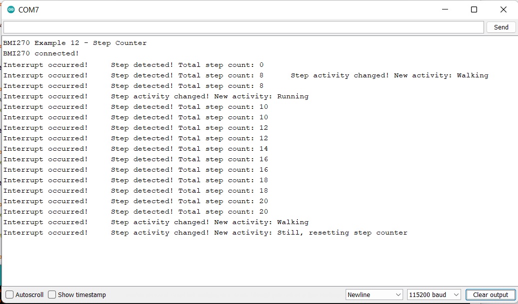
Example 12 Output