The Example2_Interrupts.ino example file can be accessed from the File > Examples > SparkFun TMAG5273 Arduino Library > Example2_Interrupts drop-down menu. This example builds upon the previous code in Example1_BasicReadings.ino. Instead of constantly streaming the sensor values from the TMAG5273, the microcontroller enables a magnetic threshold interrupt on the x-axis. Then, it waits until an interrupt is triggered on the INT pin before the data is retrieved through the I2C interface.
Example2_Interrupts.inoCode Verification
The code modification was last verified to be functional under the following parameters:
Arduino IDE Version: 2.2.1
Arduino Library Version: 1.0.3

Hardware Platform:
- SparkFun RedBoard Plus
- SparkFun Linear 3D Hall-Effect Sensor - TMAG5273 (Qwiic)
- SparkFun Mini Linear 3D Hall-Effect Sensor - TMAG5273 (Qwiic)
Required Modification
This code was developed to be utilized with the ESP32 on the IoT Motor Driver. Users will need to modify the example code, to utilize the interrupt pins of the ATmega328P on the RedBoard Plus. Replace uint8_t intPin = 4; with uint8_t intPin = 2; to utilize the D2 pin on the RedBoard Plus, which can handle interrupts.
Original Code:
/*
 * Example 2: Interrupts
 * -------------------------
Modified Code:
// Interrupt pin used// NOTE: This pin is specific to the SparkFun IoT Motor Driveruint8_tintPin=2;
/* * --------------------------------------------------------------------------------- * Copyright (c) 2025, SparkFun Electronics Inc. * * SPDX-License-Identifier: MIT * --------------------------------------------------------------------------------- *//* * Example 2: Interrupts * ------------------------- * This example demonstrates how to configure the TMAG5273 sensor to use interrupts. The example is * setup to trigger an interrupt when the X-axis magnetic field exceeds a specified threshold. * * * Hardware Connections: *. - None reqquired - this example is intended to be used with the SparkFun IoT Brushless Motor Driver * * Note: Make sure to install the SparkFun TMAG5273 Arduino Library before running this example. * You can install it via the Arduino Library Manager or download it from: * https://github.com/sparkfun/SparkFun_TMAG5273_Arduino_Library * */#include"SparkFun_TMAG5273_Arduino_Library.h" // Used to send and recieve specific information from our sensor#include<Wire.h> // Used to establish serial communication on the I2C busTMAG5273sensor;// Initialize hall-effect sensor// I2C default addressuint8_ti2cAddress=TMAG5273_I2C_ADDRESS_INITIAL;// Interrupt pin used// NOTE: This pin is specific to the SparkFun IoT Brushless Motor Driveruint8_tintPin=4;// Start the flag as falsevolatileboolinterruptFlag=false;// ISR to print what interrupt was triggeredvoidisr1(){interruptFlag=true;}voidsetup(){delay(1000);Wire.begin();// Start serial communication at 115200 baudSerial.begin(115200);// Configure Interrupt PinpinMode(intPin,INPUT);// Attach interrupt to pin 4 as a digital, falling pinattachInterrupt(digitalPinToInterrupt(intPin),isr1,CHANGE);// Begin example of the magnetic sensor code (and add whitespace for easy reading)Serial.println("");Serial.println("------------------------------------------------------------------");Serial.println("TMAG5273 Example 2: Interrupts");Serial.println("------------------------------------------------------------------");Serial.println("");// If begin is successful (0), then start exampleif(sensor.begin(i2cAddress,Wire)==true){Serial.println("Begin");}else// Otherwise, infinite loop{Serial.println("Device failed to setup - Freezing code.");while(1);// Runs forever}// Set interrupt through !INTsensor.setInterruptMode(TMAG5273_INTERRUPT_THROUGH_INT);// Set the !INT pin state - pulse for 10ussensor.setIntPinState(true);// Enable the interrupt response for the thresholdssensor.setThresholdEn(true);// int pinStatus = sensor.getInterruptPinStatus();pinMode(intPin,INPUT);// Set X, Y, Z, and T Thresholds for interrupt to be triggeredsensor.setXThreshold(5);// mT// sensor.setYThreshold(5); // mT// sensor.setZThreshold(5); // mT// sensor.setTemperatureThreshold(50); // CSerial.print("X Threshold Set: ");Serial.println(sensor.getXThreshold());}/* To use the other thresholds, simply change the names and use the other functions:- sensor.getYThreshold();- sensor.getZThreshold();- sensor.getTemperatureThreshold();*/voidloop(){if(interruptFlag==true){interruptFlag=false;Serial.print("X Threshold Reached! ");intxThresh=sensor.getXThreshold();Serial.print("X Threshold: ");Serial.println(xThresh);if(sensor.getMagneticChannel()!=0)// Checks if mag channels are on - turns on in setup{floatmagX=sensor.getXData();floatmagY=sensor.getYData();floatmagZ=sensor.getZData();floattemp=sensor.getTemp();// Serial.print("(");// Serial.print(magX);// Serial.print(", ");// Serial.print(magY);// Serial.print(", ");// Serial.print(magZ);// Serial.println(") mT");// Serial.print(temp);// Serial.println(" °C");// This examples is primarily intended for use with the SparkFun IoT Brushless Motor Driver// board, which is ESP32 based. Because of this, we are using Serial.printf for easier// formatted output. If you are using an AVR based board, you can replace this with the// commented out Serial.print statements above.Serial.printf(" Magnetic: [ X: %7.2f Y: %7.2f Z: %7.2f ] mT, Temp:\t%6.2f C\r\n",magX,magY,magZ,temp);}else{Serial.println("Mag Channels disabled, stopping..");while(1);}}else{Serial.println("Checking for Interrupts...");}delay(500);}
Hardware Connections
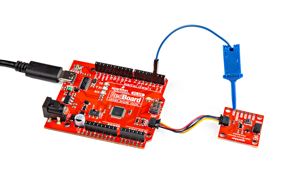
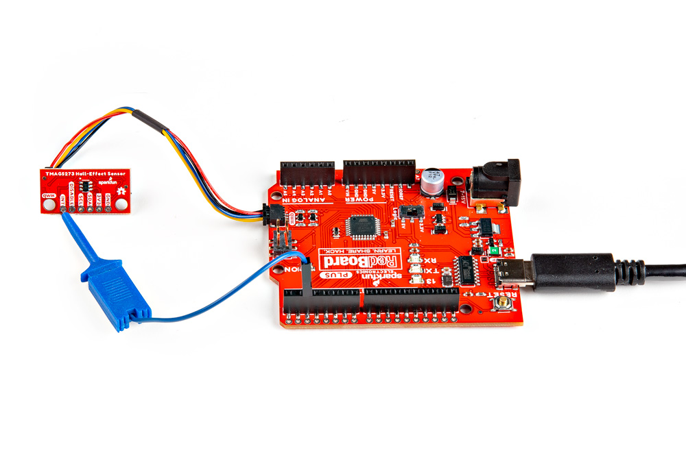
For this example, users simply need to connect their Qwiic Hall-Effect Sensor board to their microcontroller, utilizing the I2C interface and interrupt pin. Users can easily connect the I2C interface with the Qwiic connection system on their boards. To connect the interrupt pin, we recommend utilizing an IC-hook for a temporary connection.
*The Qwiic Hall-Effect Sensor boards are connected to a [RedBoard Plus](https://www.sparkfun.com/products/18158), with a [Qwiic cable](https://www.sparkfun.com/products/15081) and an [IC-hook](https://www.sparkfun.com/products/9741).*
Pin Connections
For users with a development board without a Qwiic connector, the table below illustrates the required pin connections. Make sure that the logic-level of the sensor is compatible with the development board that is being connected.
Sensor Pin
Microcontroller Pin
RedBoard/Uno
INT
Interrupt Pin
D2
SCL
I2C - Serial Clock
SCL/A5
SDA
I2C - Serial Data
SDA/A4
3V3
Power: 1.7 to 3.6V
3.3V
GND
Ground
GND
Serial Monitor
This example waits until an interrupt is triggered by the magnetic threshold before data is retrieved from the TMAG5273 sensor. The data is then displayed in the Serial Monitor.
The magnetic flux (mT) and temperature (°C) values streamed from the TMAG5273 sensor into the Serial Monitor.
Tip
For this example to work, users will need to move a magnet near the sensor to trigger the interrupt.
Warning
The casing of rare Earth magnets is often conductive. Users should take precautions to avoid shorting out the components or electrical contacts with these types of magnets.