Hardware Overview
Board Dimensions
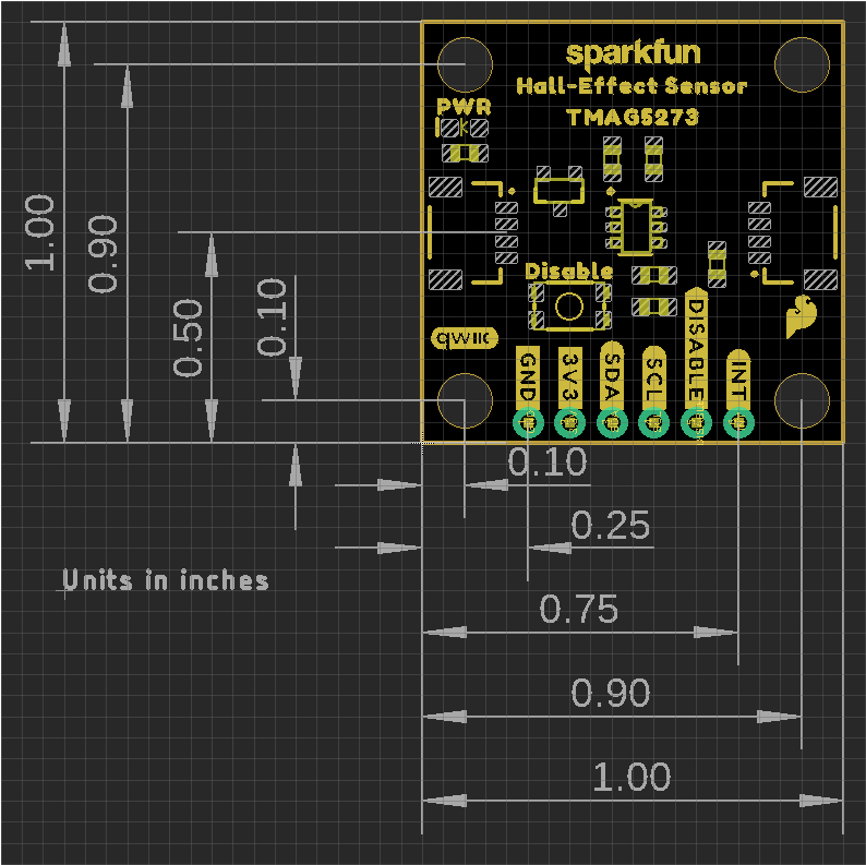
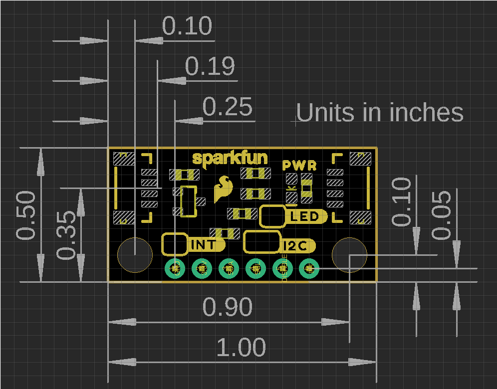
The Qwiic Hall-Effect Sensors are laid out in the standardized 0.5"x 1" (1.77 x 2.54 cm) mini form-factor and the regular, 1" x 1" (2.54 x 2.54 cm) Qwiic breakout board. These boards also include standard 0.13" mounting holes, which are compatible with 4-40 screws. The dimensions of these boards are illustrated in the drawings below, where the listed measurements are in inches.
Need more measurements?
For more information about the board's dimensions, users can download the eagle files for the boards. These files can be opened in Eagle and additional measurements can be made with the dimensions tool.
Eagle - Free Download!
Eagle is a CAD program for electronics that is free to use for hobbyists and students. However, it does require an account registration to utilize the software.
 Dimensions Tool
This video from Autodesk demonstrates how to utilize the dimensions tool in Eagle, to include additional measurements:

Power
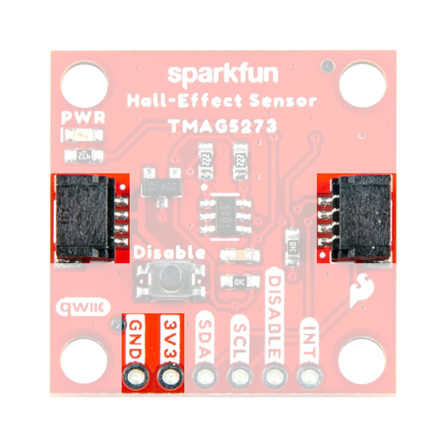
The TMAG5273 requires a supply voltage between 2.3 to 3.6V (1). This power can be provided to the board, either, through one of the polarized Qwiic connectors or the dedicated 3.3V (3V3) and ground (GND) PTH pins broken out on the board.
- While the sensor's listed voltage range is 1.7 to 3.6V, its under-voltage range is 1.9 to 2.2V. Users may find that their sensor is unresponsive below 2.3V.
Warning
The Qwiic connect system is meant to run on 3.3V. Ensure that another voltage is not being supplied through the PTH pins when utilized in conjunction with this system.
Under-Voltage Threshold
The under-voltage threshold of the TMAG5273 is 1.9 to 2.2V. It is recommended that users provide an input voltage between 2.3 to 3.6V.
Info
For more details, users can reference the schematic and the TMAG5273 datasheet.
Power Status LED
The red, PWR LED will begin to light up once ~1.4V is supplied to the board; however, for most users, it will light up when 3.3V is supplied through the Qwiic connector. A jumper is available to disconnect the power from the LED, for low-power applications (see Jumpers section below).
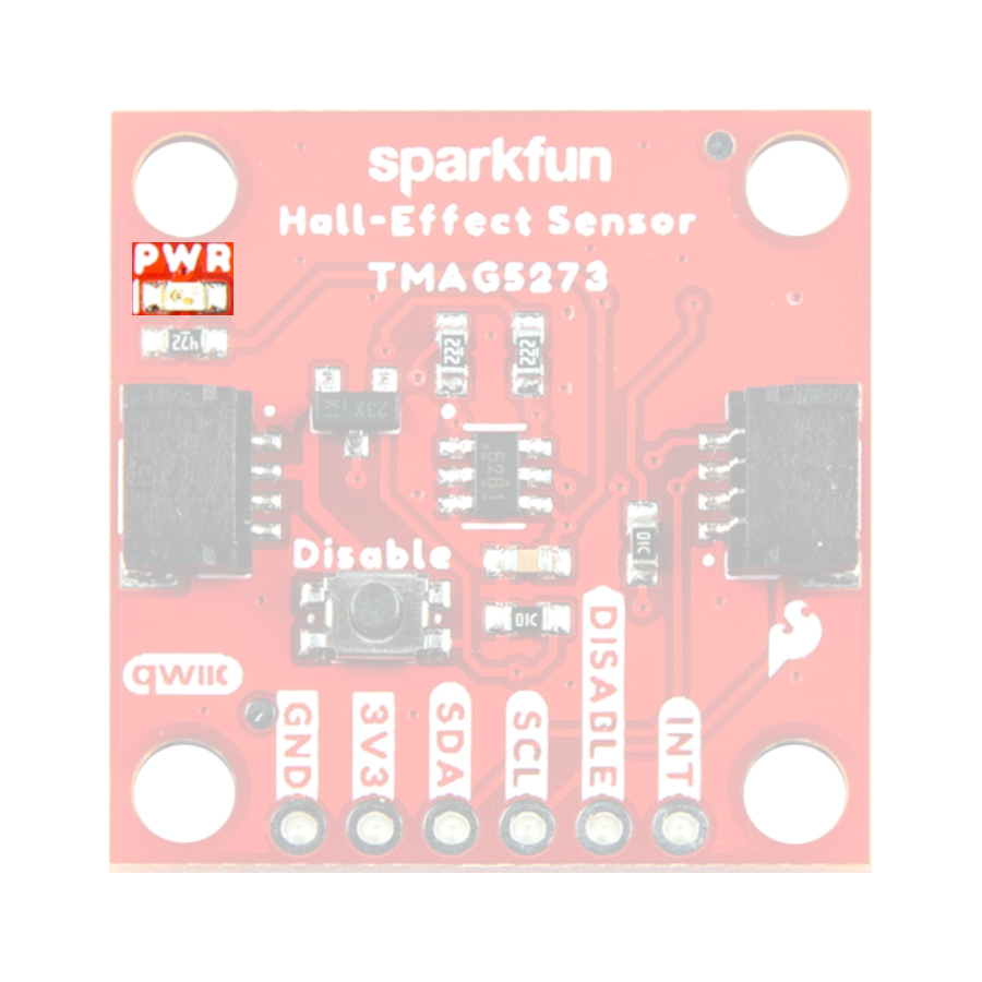
Minimum Voltage
Users should keep in mind that the forward voltage of the red LED is lower than the minimum voltage required to power the TMAG5273 sensor. Therefore, the LED could potentially be (dimly) lit, when there isn't enough voltage to power the sensor.
TMAG5273
The Qwiic Hall-Effect Sensor board features the TMAG5273 sensor from Texas Instruments. The TMAG5273 is low-power 3D hall-effect sensor that is perfect for detecting and measuring changes in a nearby magnetic field. The magnetic range of the sensor is configurable to either ±40 mT or ±80 mT. In addition, the TMAG5273 features TI's integrated angle calculation engine (CORDIC) with gain adjustment, tamper detection, and temperature compensation (for NdBFe and ceramic magnet types). The operation sensor's interrupt can be configured to trigger through the I2C interface or an interrupt pin, based upon a wake-up/threshold setting or the conversion of a new measurement.
Features:
- Configurable I2C Address:
- Default (7-bit): 0x35 (hex) or
0110101(bin)
- Default (7-bit): 0x35 (hex) or
- Operating Voltage: 1.7 to 3.6V (1)
- Current Draw:
- Active: 2.3mA
- Sleep Mode: 5nA
- Wake-Up/Sleep (@ 1Hz): 1µA
- Full-Scale Range: ±40mT or ±80mT (2)
- Accuracy: ±5% (3)
- Temperature Compensation (4)
- CORDIC Engine (5)
- Output Data Rate (Hz): (6)
- 0.05, 0.2, 0.5, 1, 2, 10, 20, 33, 50, 66, 100, 200, or 1000
- Operating Temperature: -40 to 125°C
- Interrupt Triggers:
- Threshold
- Conversion
- The sensor may be unresponsive below 2.3V; its under-voltage range is 1.9 to 2.2V
- The range on each axis
- The typical sensitivity at room temperature
- Adjusts for magnet type (NdBFe or ceramic)
- Integrated angle calculation (along a single axis)
- CRC can be enabled
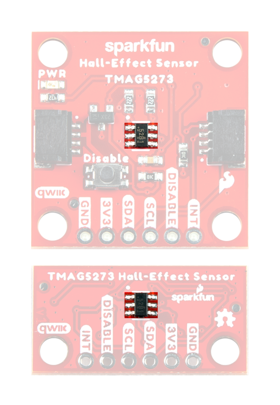
The TMAG5273 sensor on the Qwiic Hall-Effect Sensor boards.
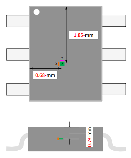
Sensor Alignment
We have positioned the TMAG5273 chip, based on the offset of the internal hall elements in the sensor.
Info
For exact measurements, users can download and reference the eagle files of the boards. We recommend referencing the sensor's position based on the board's CNC milled, mounting holes.
Note
In manufacturing, we panelize our boards on a single PCB with a v-score separation. This is an efficient method to assemble multiple boards at once. After the panel is populated, cleaned, and inspected, the individual boards are separated by slicing the v-scores.
While efficient, this process means that measurements referencing the edges of the PCB won't be as accurate when compared to the included mounting holes.
The orientation of the sensor's axes is illustrated in the figure below.
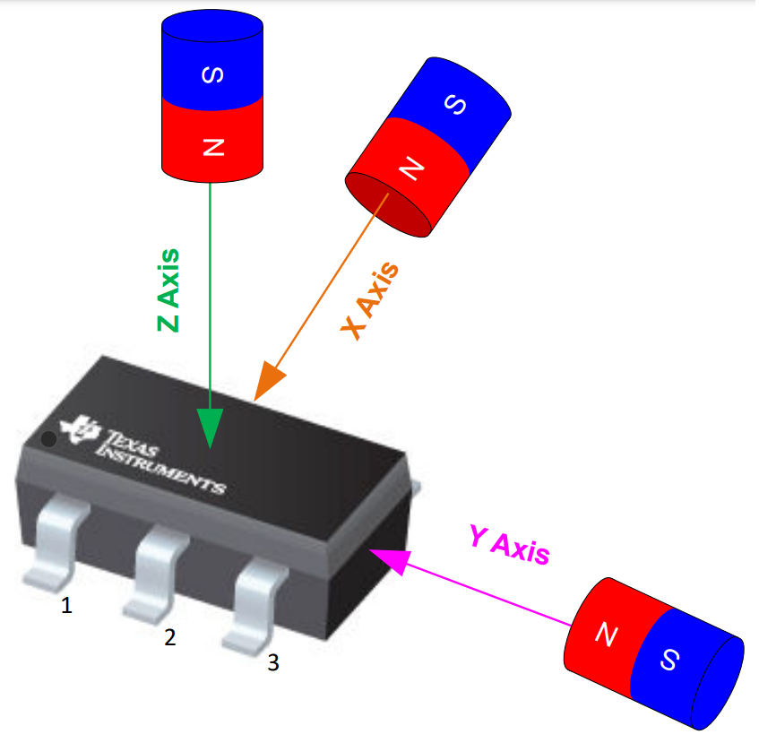
Info
The orientation of the TMAG5273 sensor is indicated by the white silkscreen dot, next to the sensor, on the PCB of the Qwiic Hall-Effect Sensor boards. That dot correlates with the black dot just below the Texas Instruments logo in the figure above.
Interrupt Operation
The interrupt function for the TMAG5273 can be set up to operate on either the INT or SCL pins. Users can also configure what triggers the interrupt, a threshold or data conversion. Control of the interrupt's operation is managed in the following registers:
DEVICE_CONFIG_2SENSOR_CONFIG_2INT_CONFIG_1
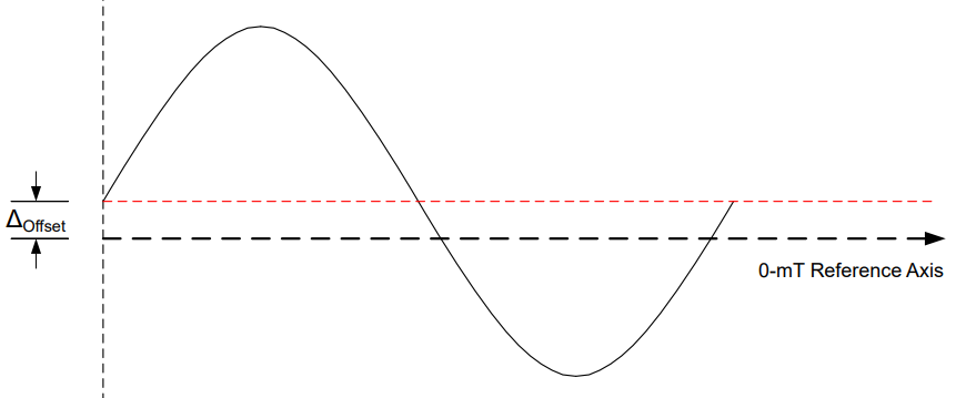
Magnetic Offset Correction
The TMAG5273 features an offset correction, on a pair of magnetic axes for situations where the sensor might be affected by a persistent magnetic field. The offsets are configured in the following registers:
MAG_OFFSET_CONFIG_1MAG_OFFSET_CONFIG_2SENSOR_CONFIG_2
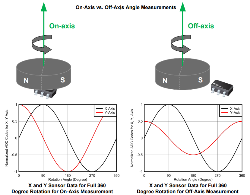
Gain Adjustment
The TMAG5273 features a gain adjustment, on a pair of magnetic axes for situations where a magnet's rotation axis is offset from the position of the sensor's hall elements. The gain adjustments are configured in the following registers:
MAG_GAIN_CONFIGSENSOR_CONFIG_2
Tamper Detection
Magnetic tamper detection can be employed with the TMAG5273 by continuously monitoring for external magnetic fields. For more details, users can reference section 8.2.1 of the TMAG5273 datasheet and the application note.
Info
For more details, users can reference the TMAG5273 datasheet.
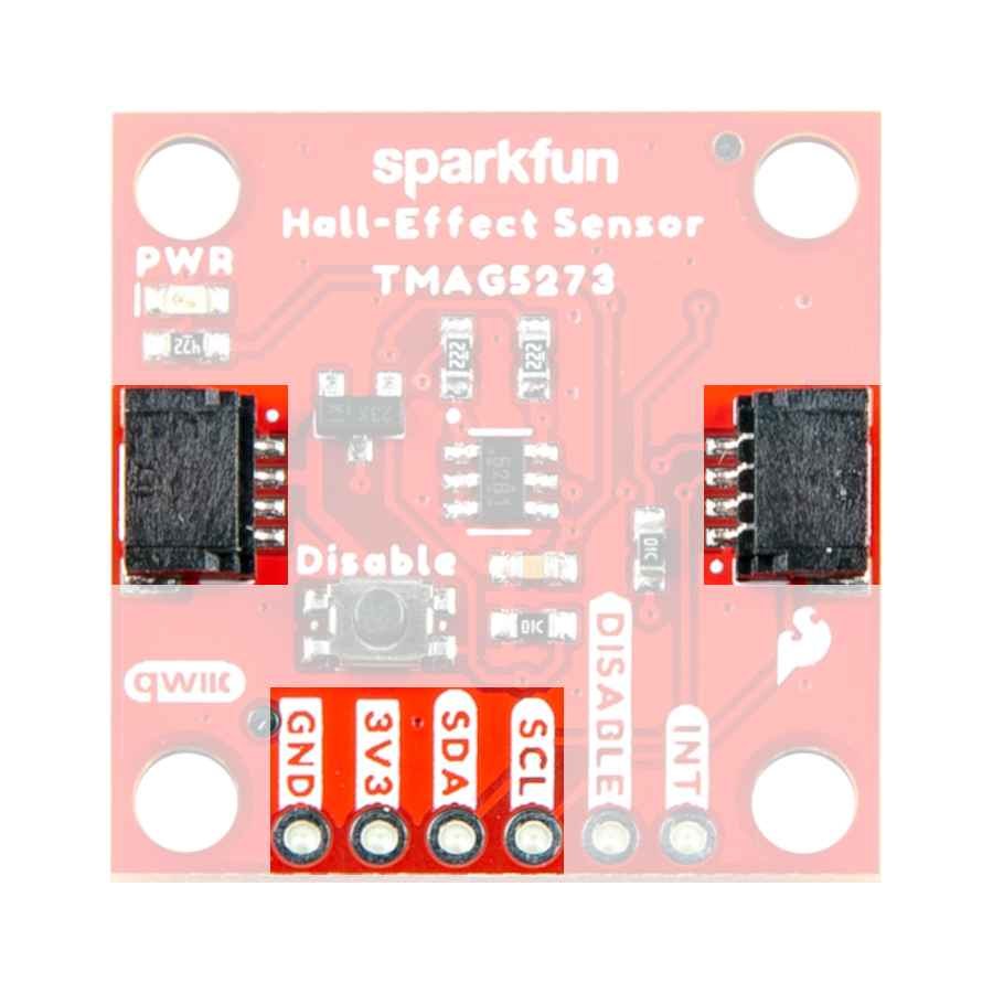
Breakout Pins
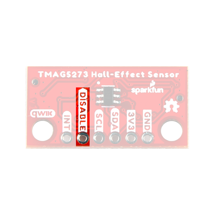
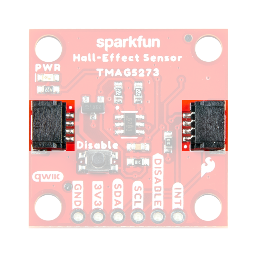
There are six PTH pins broken out on the Qwiic Hall-Effect Sensor boards. The pins are evenly spaced at 0.1" on the outer edge of the board; perfect for attaching headers. These pins provide access to the I2C interface and interrupt pin of the TMAG5273 sensor; and included is a DISABLE pin that controls the power to the sensor.
Note
The I2C interface can also be accessed through the Qwiic connectors on the board.
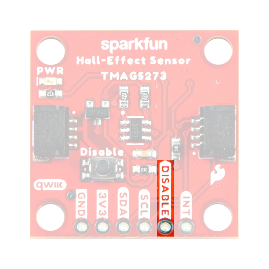
Disable Pin
Unfortunately, the TMAG5273 doesn't incorporate a software reset. The intended use of the TMAG5273 is to hard reset the sensor's power with a GPIO pin. However, with the Qwiic connect system, users may not want to power cycle the other Qwiic devices on the system. Therefore, we have incorporated DISABLE pin whose circuitry allows users to reset the TMAG5273, without interrupting the power of the Qwiic connect system.
Info
For more details, users can reference the schematic and the TMAG5273 datasheet.
Disable Button
A Disable button is only provided on the regular, 1" x 1" Qwiic board. This button is connected to the same reset circuitry of the DISABLE pin.
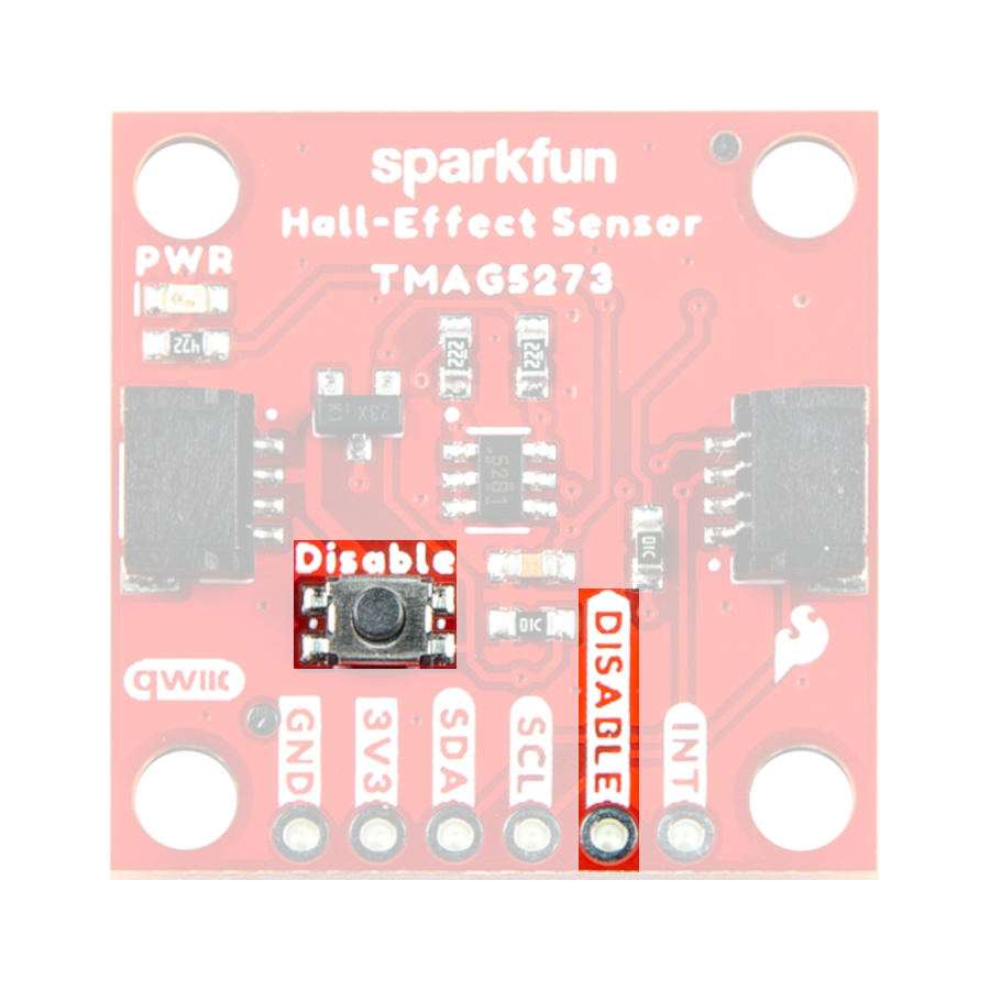
The Disable button on the Qwiic Hall-Effect Sensor.
Tip
The button casing appears to be ferromagnetic. Therefore, a strong magnetic field (i.e. from a rare Earth magnet) could potentially exert enough force to rotate or lift the board.
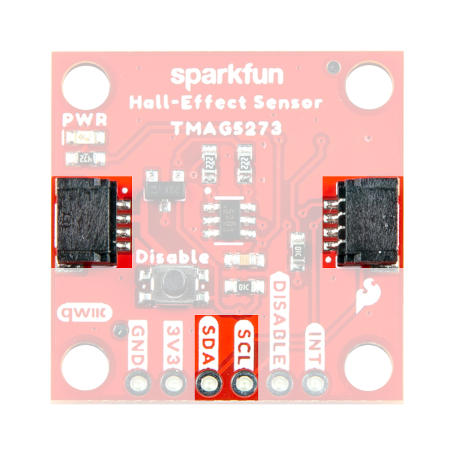
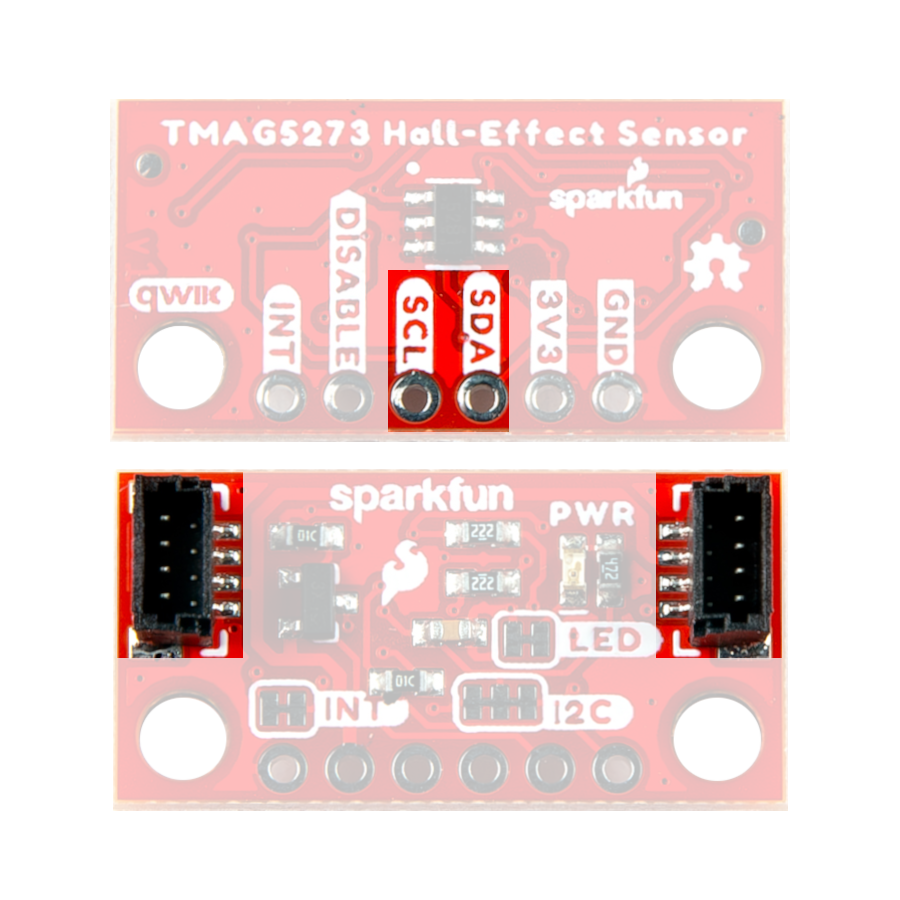
I2C Pins
The I2C interface can also be accessed either through the breakout pins or the Qwiic connectors on the board. In most cases, the Qwiic connector will be the simplest method to connect the Qwiic Hall-Effect Sensor boards to a microcontroller.
Qwiic Connector
Qwiic connectors are provided for users to seamlessly integrate I2C devices with SparkFun's Qwiic Ecosystem.
Interrupt Function
TI does not recommend sharing the same I2C bus with multiple secondary devices when using the SCL pin for interrupt function. The SCL interrupt may cause bus contention issues that would corrupt the I2C transactions with other secondary devices, when present on the same I2C bus.
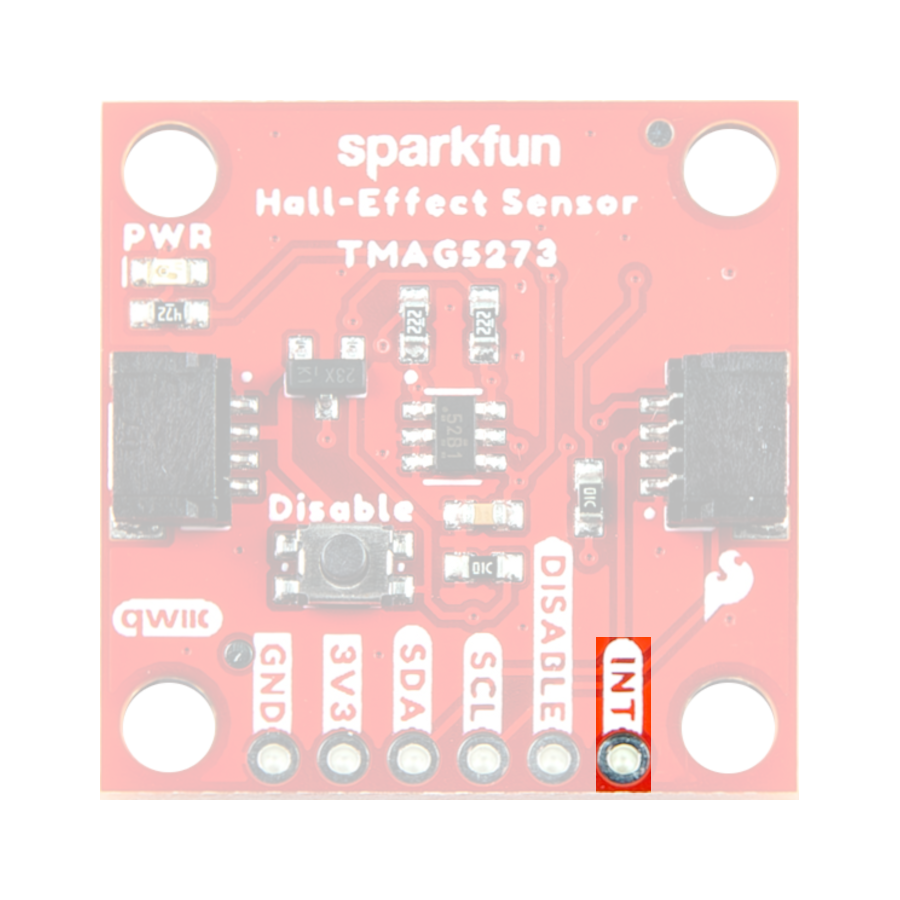
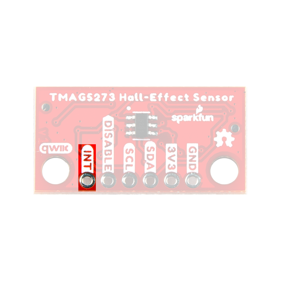
Interrupt Pin
The interrupt function can be configured to operate through either the SCL or INT pins. When utilizing the interrupt pin (INT), the interrupt function can be configured to trigger once a conversion is completed or when a magnetic threshold has been surpassed.
Qwiic Connectors
Qwiic connectors are provided for users to seamlessly integrate with SparkFun's Qwiic Ecosystem. Otherwise, users can access the I2C interface through the PTH pins broken out on the board.
What is Qwiic?
The Qwiic connect system is a solderless, polarized connection system that allows users to seamlessly daisy chain I2C boards together. Play the video below to learn more about the Qwiic connect system or click on the banner above to learn more about Qwiic products.
Features of the Qwiic System


Qwiic cables (4-pin JST) plug easily from development boards to sensors, shields, accessory boards and more, making easy work of setting up a new prototype.


There's no need to worry about accidentally swapping the SDA and SCL wires on your breadboard. The Qwiic connector is polarized so you know you’ll have it wired correctly every time, right from the start.
The PCB connector is part number SM04B-SRSS (Datasheet) or equivalent. The mating connector used on cables is part number SHR04V-S-B or an equivalent (1mm pitch, 4-pin JST connector).


It’s time to leverage the power of the I2C bus! Most Qwiic boards will have two or more connectors on them, allowing multiple devices to be connected.
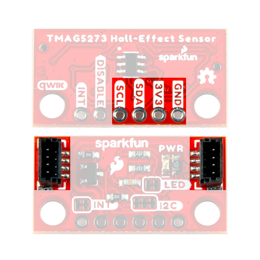
Jumpers
Never modified a jumper before?
Check out our Jumper Pads and PCB Traces tutorial for a quick introduction!
-

How to Work with Jumper Pads and PCB Traces
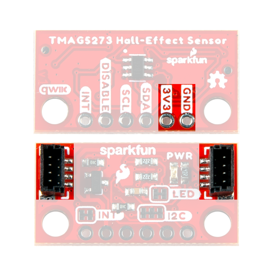
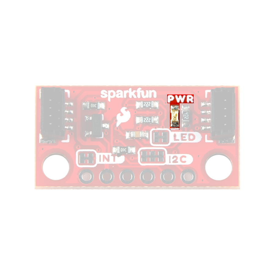
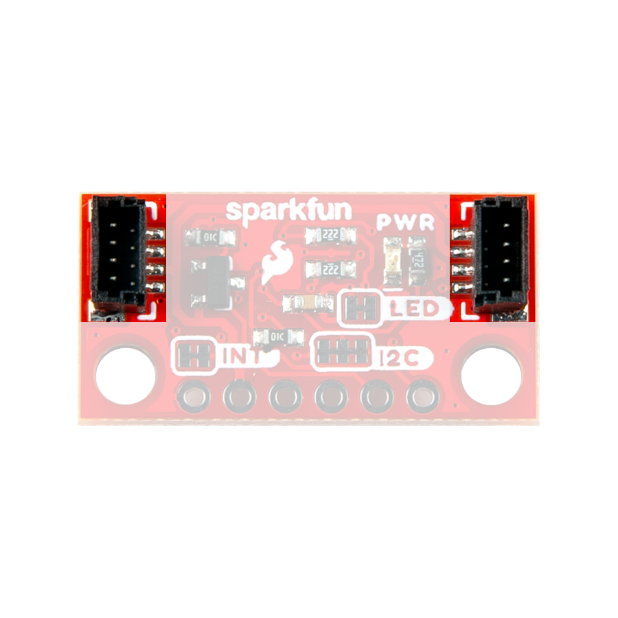
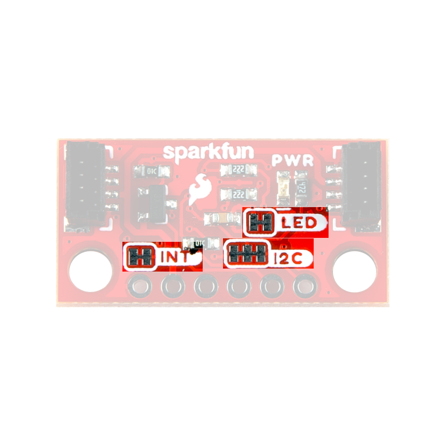
There are three jumpers on the back of the board that can be used to easily modify the hardware connections of the board.
- LED - This jumper can be used to disconnect power from the red, power LED for low-power applications.
- I2C - This jumper can be used to remove the pull-up resistors on the I2C bus.
- INT - This jumper can be used to remove the pull-up resistor from the
INTpin.
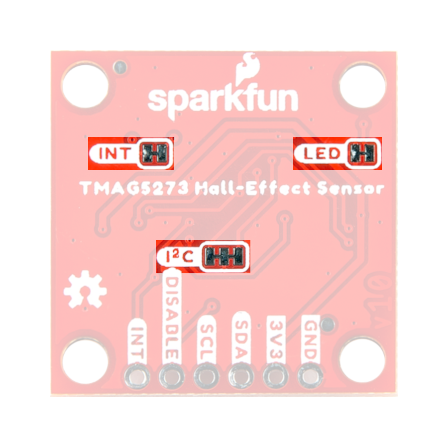
Jumpers on the back of the Qwiic Hall-Effect Sensor board.
Jumpers on the Qwiic Hall-Effect Sensor board.