Hardware Assembly - Qwiic Relay - 1x1A DPDT
Qwiic Assembly
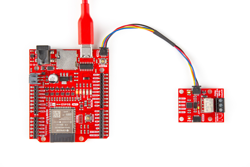
We'll start by connecting the Qwiic Relay to the RedBoard IoT - ESP32. Just plug one end of the Qwiic cable into the Qwiic Relay and the other into the RedBoard IoT - ESP32 like the photo below:
AC Load Assembly
Make sure the cable is not plugged into the wall as you cut into the wire in the following section. Not sure about what color insulation wiring is used in you region? Check out the standard wire insulation colors listed online for reference. If you are unsure about the standard wiring color in your region, please consult a certified electrician to connect to the AC input voltage side.
- Start by cutting the live AC line (usually black or red) and stripping a small amount of insulation away from the ends of the cut wire.
- Insert one end of the cut wire into the
COMscrew terminal and tighten it to secure the wire. - Insert the other end of the cut wire either into the
NCorNOscrew terminal depending on whether the device will normally be on or off.- If the device will normally be on and switched off, connect this end to
NC. - If the device will normally be off and switched on, connect this end to
NO.
- If the device will normally be on and switched off, connect this end to
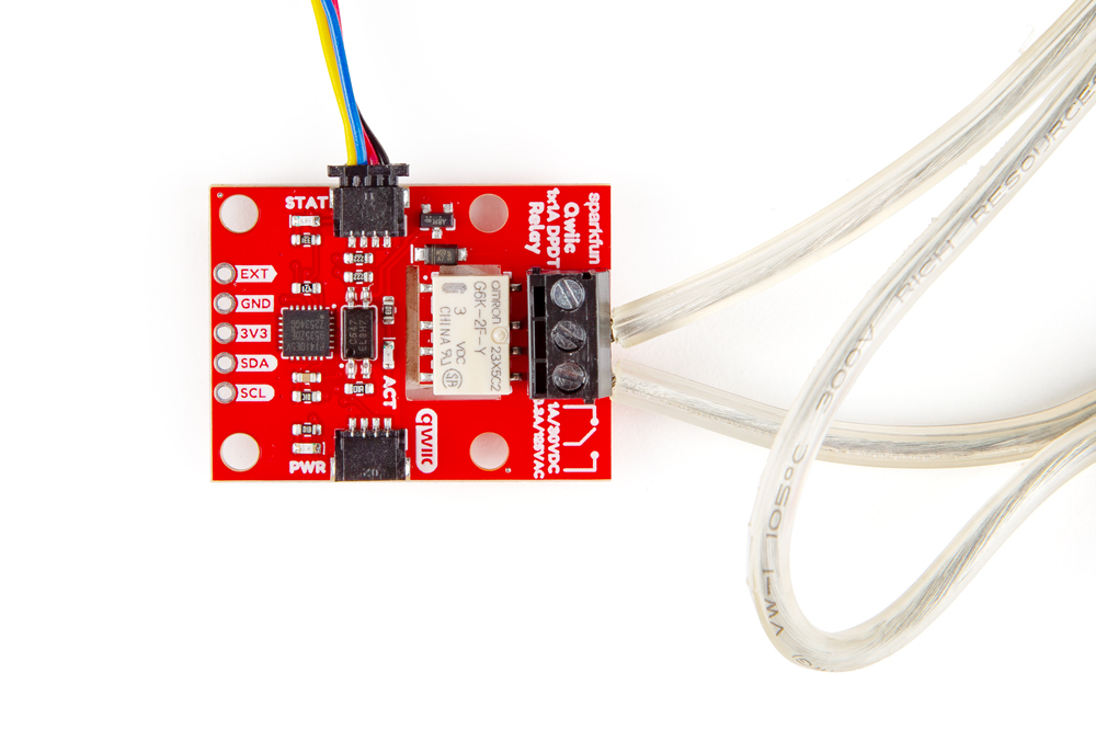
We connected the AC load to normally be off so the wires in the photo connect to the COM and NO terminals:
Warning! Make sure that your wires connecting to the wall outlet are secure and are rated to handle the current! Please be careful when handling the contacts when the cable is plugged into a wall outlet. Touching the contacts while powered could result in injury.
Looking for information about safety and insulation? Check out the notes about Safety and Insulation from our Beefcake Relay Control Kit.
With everything connected up, your circuit should look similar to the photo below. Now let's upload some code to turn the load on and off.