Hardware Overview - Qwiic Relay - 1x1A DPDT
Let's take a closer look at the components on the Qwiic Relay - 1x1A DPDT.
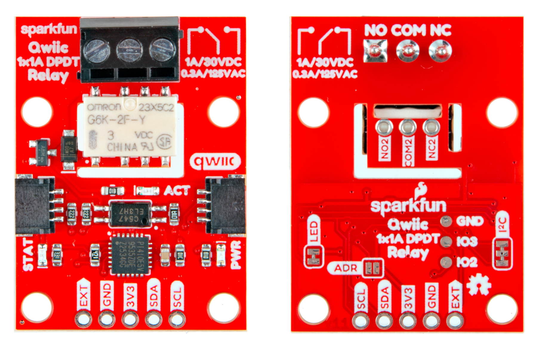
1A Dual-Pole/Dual-Throw Relay
The G6K-2F-Y Dual-Pole/Dual-Throw (DPDT) relay from Omron Electronic Components handles switching loads of 1A/30VDC and 0.3A/125VAC (at 40°C) with very low drive currents. The design of this board lets users drive the relay over I2C or through an external drive pin. Driving the relay over I2C requires up to 5.8mA while driving it from an external source requires up to 33mA.
The board isolates the high-power side of the relay with both a physical air-gap in the PCB along with an opto-isolator circuit. For detailed information on the G6K-2F-Y, refer to the datasheet.
Load Connections
This relay board includes two connection types for the relay's two poles. The main (COM) pole connects to a 3-pin screw terminal for solderless connection of a load. In order to conserve space on the board, the second (COM2) pole connects to three 0.1"-spaced plated through-hole pins on the bottom of the board.
TCA9555 I2C GPIO Expander
The Qwiic Relay uses a TCA9555 I2C GPIO Expander to control the relay over I2C. The TCA9555 is a 16-bit I/O expander that is configured in the Arduino example to have two of its pins act as outputs to control the relay's signal line and the green status LED. This allows the drive current for the relay to just be up to 5.8mA. The board sets the TCA9555's I2C address to 0x20 by default. Users can set the GPIO Expander to the alternate address, 0x21, by closing the ADR jumper. For a complete overview of the TCA9555, refer to the datasheet
Connectors
Qwiic Connectors
The Qwiic Relay has a pair of Qwiic connectors to power and control the board from a microcontroller over I2C.
PTHs
The Qwiic Relay has one 0.1"-spaced plated through-hole (PTH) header that breaks out the board's power pins, I2C pins (SDA/SCL) as well as an external drive pin to control the relay from a connected I/O pin or other external input. The external drive pin requires 33mA to drive the relay.
LEDs
This board has three LEDs labeled PWR, STAT and ACT. The red Power (PWR) LED indicates when the board has power over 3.3V. The green Status (STAT) LED connects to P01 on the GPIO Expander IC. This LED can be used as a visual indicator for a variety of statuses. The example code turns it on whenever the relay is active. The green Activity (ACT) LED connects to the output of the optoisolator and turns on whenever the relay is switched on.
Solder Jumpers
The Qwiic Relay has three solder jumpers labeled LED, ADR and I2C. The LED jumper completes the power LED circuit and is CLOSED by default. Open this jumper to disable the power LED. The ADR jumper controls the GPIO Expander IC's I2C address and is OPEN by default to set the I2C address to 0x20. Close the ADR jumper to switch the GPIO Expander's I2C address to 0x21. The I2C jumper pulls the I2C lines (SDA/SCL) to 3.3V through a pair of 2.2kΩ resistors. Completely open this jumper to disable pullups on the bus.
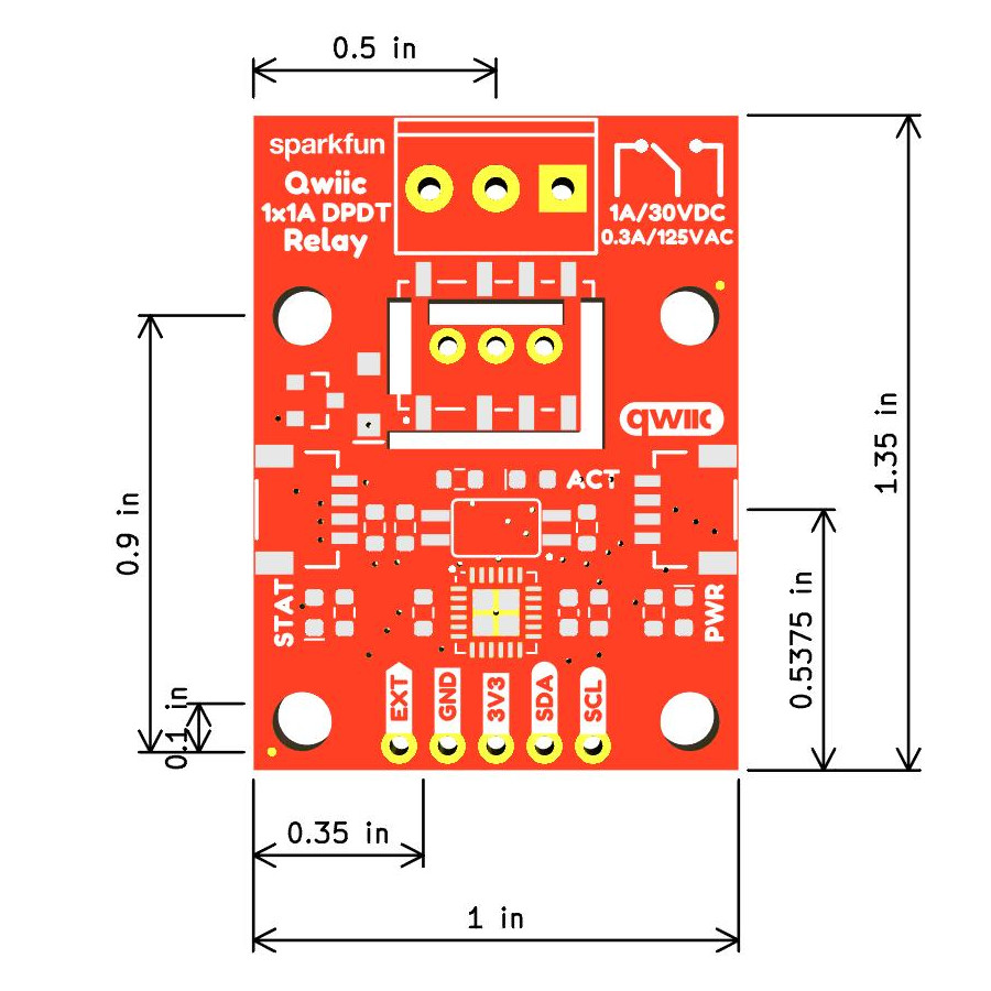
Board Dimensions
The Qwiic Relay 1x1A - DPDT measures 1" x 1.35" (25.40mm x 34.29mm) and has four mounting holes that fit a 4-40 screw.