Ports Menu
- EVK:
- Facet mosaic:
- Postcard:
- Torch:
- TX2:

Setting the baud rates of the two available external ports
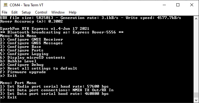
Baud rate configuration of the RADIO and DATA ports
The RADIO and DATA ports vary between RTK devices:
- The RTK Facet mosaic has both RADIO and DATA ports.
- The RTK Torch and TX2 do not have a RADIO or DATA port, but can output NMEA over USB.
- The RTK Postcard has both RADIO and DATA ports.
- The RTK EVK has only a RADIO port.
Radio Port
Available on devices that have an external RADIO port.
The RADIO port is connected directly to a UART on the GNSS receiver allowing output of NMEA or RTCM, and receiving RTCM corrections. Depending on the platform, the port is set to 57600bps to match the Serial Telemetry Radios that are recommended to be used with the RTK Facet (it is a plug-and-play solution). This can be set from 4800bps to 921600bps.
The default RADIO baud rate for the RTK Postcard is 115200bps.
Data Port
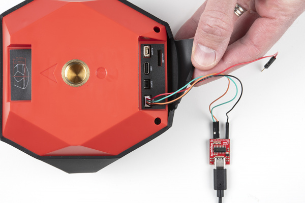
DATA port connected to a SparkFun USB C to Serial adapter
The DATA port can be configured from 4800bps to 921600bps. The default depends on the GNSS model: e.g. 460800bps on LG290P, 230400bps on other models. The default rate was chosen to support applications where a large number of messages are enabled and a large amount of data is sent. If you need to decrease the baud rate to 115200bps or other on the ZED-F9P, be sure to monitor the MON-COMM message within u-center for buffer overruns. A baud rate of 115200bps and the NMEA+RXM default configuration at 4Hz will cause buffer overruns.
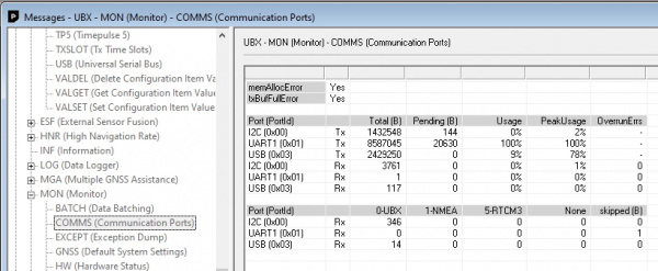
Monitoring the COM ports on the ZED-F9P
If you must run the data port at lower speeds, and you need to enable a large number of messages and/or increase the fix frequency beyond 4Hz, be sure to verify that UART1 usage stays below 90%. The image above shows the UART1 becoming overwhelmed because the ZED cannot transmit at 115200bps fast enough.
Most applications do not need to plug anything into the DATA port. Most users will get their NMEA position data over Bluetooth. However, this port can be useful for sending position data to an embedded microcontroller or single-board computer. The pinout is 3.3V / TX / RX / GND. 3.3V is provided by this connector to power a remote device if needed. While the port is capable of sourcing up to 600mA, we do not recommend more than 300mA. This port should not be connected to a power source.
Postcard USB Ports

RADIO and DATA ports on the RTK Postcard

Dual serial ports show in Device Manager
The DATA port on the RTK Postcard is the USB C connector. This connection creates two serial ports. SERIAL-A is used for Serial Configuration. SERIAL-B is connected to the DATA port of the LG290P to receive NMEA and other data directly. The DATA port is also used for updating the firmware on the LG290P.
Output GNSS Data over USB
Enabling Output GNSS data to USB serial will pipe all GNSS output (generally NMEA but also RTCM) to the USB serial connection. This permits a wired connection to be made on devices, such as the RTK Torch or TX2, that have only one external port (USB).
Note
To exit this mode, press +++ to open the configuration menu.
On RTK Facet mosaic, data can be output on the USB1 USB COM port.
Additionally, corrections may be sent to the device over USB. RTCM corrections received over USB will follow the Corrections Priority table.
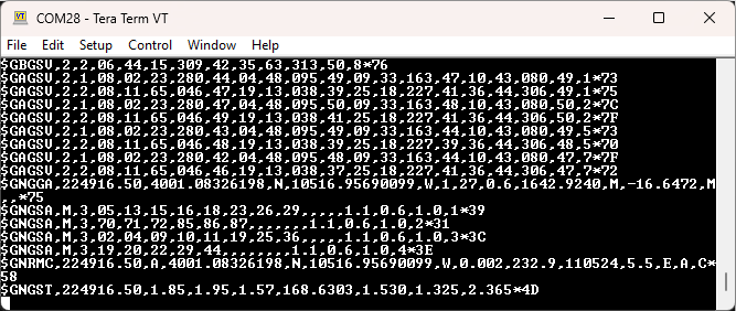
Example NMEA output over USB
Limit RADIO Port Output to RTCM
Enabling this option will turn off all data output to the RADIO port except for the minimum RTCM messages necessary for RTK work. This is helpful in situations where a telemetry radio is used for connecting a Rover to a Base. Extra NMEA and binary data can tax a radio link and may cause the link to become intermittent or fail.
Allow Incoming Corrections on COM/UART
Disable this feature to block corrections on the given port.
If a GNSS receiver gets corrections from multiple sources (WiFi, Bluetooth, serial, etc) it can lead to unpredictable outcomes. To avoid this, RTK Everywhere firmware includes a sophisticated 'corrections controller' to give priority to the various sources, discarding any lower priority corrections sources that are detected. See the Corrections Priority section for more information. Because the RTK Everywhere firmware cannot filter out corrections from a serial connection, this option allows a user to disable that correction source that may .
Mux Channel
Available on devices that have a built-in multiplexer on the DATA port.
The DATA port on the RTK Facet is very flexible. Internally the DATA connector is connected to a digital mux allowing one of four software-selectable setups. By default, the port will be connected to the GNSS UART and output any messages via serial.
- GNSS TX Out/RX In - The TX pin outputs any enabled messages (NMEA, RTCM and binary). If supported, the RX pin can receive RTCM for RTK and can also receive configuration commands.
- PPS OUT/Event Trigger In - The TX pin outputs the pulse-per-second signal that is accurate to typically 30ns RMS. The RX pin is connected to the EXTINT pin on the ZED-F9P or EVENTA on the mosaic-X5, allowing events to be measured with incredibly accurate nano-second resolution. See the Pulse Per Second and External Trigger section below for more information.
- I2C SDA/SCL - The TX pin operates as SCL, RX pin as SDA on the I2C bus. This allows additional sensors to be connected to the I2C bus, typically sharing it with the GNSS and OLED. This is useful for custom applications where you are using your own firmware.
- ESP32 DAC Out/ADC In - The TX pin operates as a DAC-capable GPIO on the ESP32. The RX pin operates as an ADC-capable input on the ESP32. This is useful for custom applications where you are using your own firmware. These pins have no function with the standard RTK Everywhere firmware.
Pulse Per Second and External Trigger
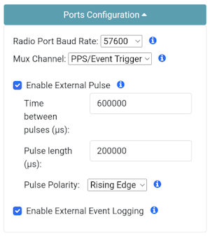
Configuring the External Pulse and External Events over WiFi
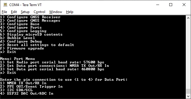
Port menu showing mux data port connections
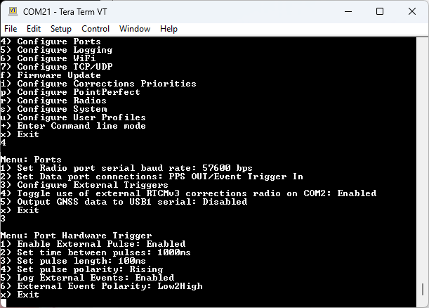
Configuring the External Pulse and External Events on RTK Facet mosaic
When PPS OUT/Event Trigger In is selected, the Pulse-Per-Second output from the GNSS is sent out of the TX pin of the DATA port. Once the RTK device has GNSS reception, this can be used as a very accurate time base.
The pulse width, frequency and polarity are configurable. The absolute timing accuracy depends on the GNSS.
The DATA port RX pin is routed to the GNSS EXTINT / EVENTA pin, allowing external events and triggers to be captured precisely. The absolute timing accuracy depends on the GNSS. For products using the u-blox ZED-F9P GNSS, the event timing is recorded in the UBX-TIM-TM2 binary message. On the mosaic-X5, the ExtEvent and ExtEventPVTCartesian SBF binary messages capture the timing and position of events.
For PPS, only the Black and Green wires are needed. For external events / triggers, only the Black and Orange wires are needed.
If you need to provide 3.3V to your system, the red wire can supply up to 600mA but we do not recommend sourcing more than 300mA.
- Red - 3.3V
- Green - TX (3.3V PPS output from the RTK device)
- Orange - RX (3.3V external trigger input into the RTK device)
- Black - GND
For products using the u-blox ZED-F9P GNSS, see the Timemark section of the ZED-F9P Integration Manual