Hardware Overview
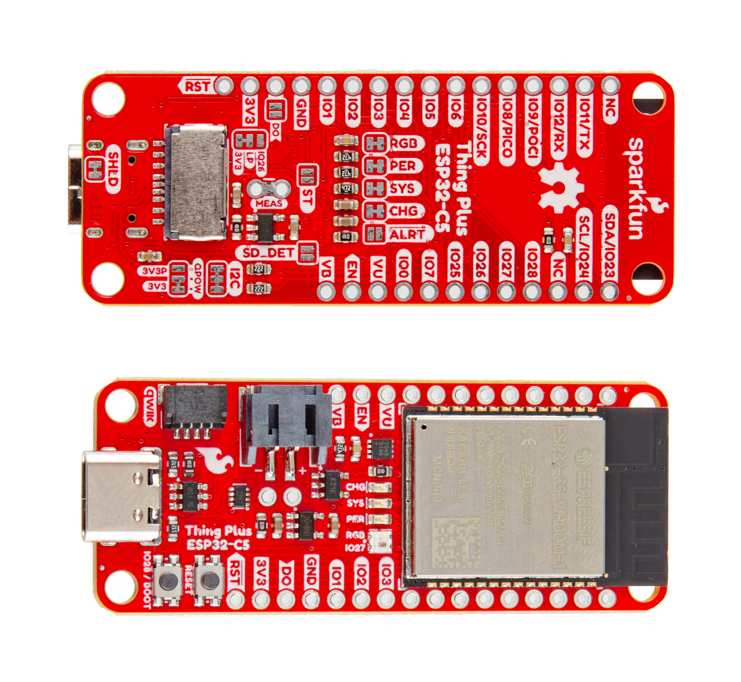
Let's take a closer look at the Thing Plus - ESP32-C5 and the hardware on the board.
ESP32-C5
The ESP32-C5 is a wireless module that supports 2.4 and 5GHz dual-band WiFi along with Bluetooth 5, Zigbee and Thread. The module is built around a 34-bit RISC-V single-core processor. This Thing Plus uses the ESP32-C5-WROOM-1 which 8MB Flash and 8MB of PSRAM storage with an integrated PCB antenna. It offers the typical peripherals you'd expect from an ESP32 module including 22 multifunction GPIO, SPI, UART, I2C, I2S, USB Serial/JTAG controller, ADC and more. For complete information on the ESP32-C5, refer to the datasheet.
Power Components
The Thing Plus ESP32-C6 includes several options for powering including USB-C, LiPo battery with on-board battery charging and monitoring circuits as well as direct power inputs.
USB-C Connector
The USB-C connector on the board acts as the primary serial interface for the ESP32-C6 module as well as a power input. It connects directly to the ESP32-C6's USB serial converter. The 5V USB input voltage is regulated down to 3.3V through a voltage regulator with a max current of 500mA@3.3V.
2-Pin JST Connector, Battery Charger, & Fuel Gauge
The board has a 2-pin JST connector to connect a single-cell Lithium Ion (LiPo) battery for battery-powered applications. It also has an MCP73831 battery charger to charge an attached battery and a MAX17048 fuel gauge to monitor battery voltage levels over I2C. The charge rate is set to 214mA@3.3V. The MCP73831 receives power from the V_USB line so it only is powered when 5V is provided either over USB or the V_USB PTH pin. If applying voltage directly to the V_USB pin make sure it does not exceed 5.5V.
Pinout & Qwiic Connector
Next up let's take a look at the Thing Plus pinout and Qwiic connector on this board.
PTH Headers
The Thing Plus routes all of the ESP32-C6's GPIO pins to a pair of 0.1"-spaced headers on either side of the board. This includes all six of the 12-bit ADC-capable pins, one UART, one I2C bus (SDA/SCL), one SPI interface (POCI/PICO/SCK), and six GPIO pins. Many of the GPIO connect to peripheral functions on the board by default through solder jumpers. If you'd like to free up these pins for an alternate use, make sure to adjust the solder jumpers to enable/disable the preferred functionality. Refer to the Solder Jumpers section below for more information on adjusting GPIO functions.
Qwiic Connector
There's a Qwiic connector on the board tied to the ESP32-C6's Low Power I2C bus (I/O pins 6 and 7) for easy integration into SparkFun's Qwiic ecosystem. The Qwiic connector provides connections for SDA, SCL, 3.3V, and Ground.
Buttons
There are two buttons on the board labeled RESET and BOOT. The RESET button is tied to the ESP32-C6's Enable (EN) pin and resets the module when pressed. The BOOT button puts the ESP32-C6 into bootloader mode when held down during power on or reset.
µSD Card Slot
This board also has a friction-fit µSD card slot for users who need more storage space on the Thing Plus - ESP32-C6. The slot connects the SD card's communication interface to the ESP32-C6's SPI interface using the following pins:
- SD Serial Data Out: IO9/POCI
- SD Serial Data In: IO8/PICO
- SD Serial Clock: IO10/SCK
- SD Chip Select: IO25/CS
- SD Detect: IO7/SD_DET (Not Connected by Default)
LEDs
This Thing Plus has four LEDs labeled SYS, PER, CHG, and STAT. The red Power (PWR) LED indicates whenever the 3.3V circuit is powered. The yellow Charge (CHG) LED indicates whenever the MCP73831 is charging a connected LiPo battery. The WS2812 RGB Status (STAT) LED connects the LED's Data In signal to IO23.
Solder Jumpers
The Thing Plus - ESP32-C5 has thirteen solder jumpers labeled RGB, PER, SYS, CHG, ALRT, ST, SD_DET, DO, IO26/LP/3V3, MEAS, I2C, QPOW and SHLD. The list below outlines the functionality, default states and any notes about using the solder jumpers.
- RGB - The RGB jumper connects the WS2812 RGB LED's Data In pin to IO27 on the C5. It is CLOSED by default. Open the solder jumper to disconnect IO27 from the RGB LED if needed for other uses.
- PER - The PER jumper completes the peripheral power LED circuit. It is CLOSED by default. Open the jumper to disable the peripheral power indicator LED.
- SYS - The SYS jumper completes the system power LED circuit. It is CLOSED by default. Open the jumper to disable the system power indicator LED.
- CHG - The CHG jumper completes the battery charging indicator LED circuit. It is CLOSED by default. Open the jumper to disable the battery charging LED.
- ALRT - The ALRT jumper allows users to connect the Battery Fuel Gauge's alert pin to IO0 on the C5. It is OPEN by default. Close the jumper to monitor the fuel gauge alert signal on IO0.
- ST - The ST jumper allows users to connect the voltage regulator's status pin to IOA6 on the C5. It is OPEN by default. Close the jumper to measure the status signal on IO6. This signal is HIGH when using VBAT and LOW when using VUSB.
- SD_DET - The SD_DET lets users connect the microSD card SD detect pin to IO7 on the C5. It is OPEN by default. Close the jumper to monitor the SD detect signal on IO7.
- DO - The DO jumper allows for connecting the RGB LED's data output to the AREF pin. It is OPEN by default. Close this jumper to connect the RGB LED's data output to the AREF pin to daisy-chain other WS2812 LEDs to this pin.
- IO26/LP/3V3 - The IO26/LP/3V3 jumper is a three-way jumper that lets users control low power settings using IO26 on the C5. It defaults to have the 3.3V regulator enabled at all times. Switching the jumper from 3V3 to LP lets users control the regulator using IO26 to toggle the regulator on and off. Driving the IO HIGH enables the regulator, driving it LOW disables it.
- MEAS - The MEAS jumper lets users measure the Thing Plus' total current draw. It is CLOSED by default. Open it to use a multimeter on the two PTHs on either side of the jumper to measure the board's total current consumption.
- I2C - The I2C jumper pulls the I2C lines (SDA/SCL) to 3.3V through a pair of 2.2lΩ resistors. This three-way jumper is CLOSED by default. Completely open this jumper to disable pullups on the I2C bus.
- QPOW - The QPOW jumper is a three-way jumper that selects how to power the Qwiic connector. By default it sets Qwiic power to the system voltage. Switching from 3V3 to 3V3P sets the Qwiic connector's power to come from the peripheral voltage.
- SHLD - The SHLD jumper connects the USB-C connector's shield pin to the board's ground. It is CLOSED by default. Open this jumper to isolate the USB-C shield from the board.
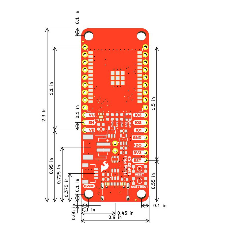
Board Dimensions
The Thing Plus - ESP32-C5 matches the standard Thing Plus footprint and measures 2.3" x 0.9" (mm x mm) and has four mounting holes that fit a 4-40 screw.