Arduino Examples
Example 1: Basic Color Sensing
This first example just does some basic measurements. To find Example 1, go to File > Examples > SparkFun Color Sensor OPT4048 > example1_BasicColorSensing:

Finding Example 1
Alternatively, you can expand the link below and copy and paste the code into a shiny new Arduino sketch:
Example 1: Basic Color Sensing
/*
Example 1 - Basic Color Sensing

This example shows the basic operation of the OPT4048 Color Sensor.
If you're curious about CIE 1931 color space, check out this link:
https://en.wikipedia.org/wiki/CIE_1931_color_space

Written by Elias Santistevan @ SparkFun Electronics, July 2023

Products:
    Qwiic 1x1: https://www.sparkfun.com/products/22638
    Qwiic Mini: https://www.sparkfun.com/products/22639

Repository:
    https://github.com/sparkfun/SparkFun_OPT4048_Arduino_Library

SparkFun code, firmware, and software is released under the MIT
License (http://opensource.org/licenses/MIT).
*/

#include "SparkFun_OPT4048.h"
#include <Wire.h>

SparkFun_OPT4048 myColor;

void setup()
{
    Serial.begin(115200);
    Serial.println("OPT4048 Example 1 Basic Color Sensing.");

    Wire.begin();

    if (!myColor.begin()) {
        Serial.println("OPT4048 not detected- check wiring or that your I2C address is correct!");
        while (1) ;
    }

    myColor.setBasicSetup();

    Serial.println("Ready to go!");
}


void loop()
{
    Serial.print("CIEx: ");
    Serial.print(myColor.getCIEx());
    Serial.print(" CIEy: ");
    Serial.println(myColor.getCIEy());
    // Delay time is set to the conversion time * number of channels
    // You need three channels for color sensing @ 200ms conversion time = 600ms.
    delay(200);
}
Make sure you've selected the correct board and port in the Tools menu and then hit the upload button. Once the code has finished uploading, go ahead and open a Serial Monitor. You should see something similar to the following.
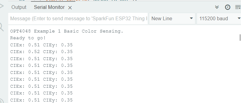
Example 1 Output
The CIEx and CIEy values are going to fall somewhere between 0 and 1. Page 35 of the datasheet gives more detail on this, but generally speaking, you can map the predominant color of the space you're measuring using the following:
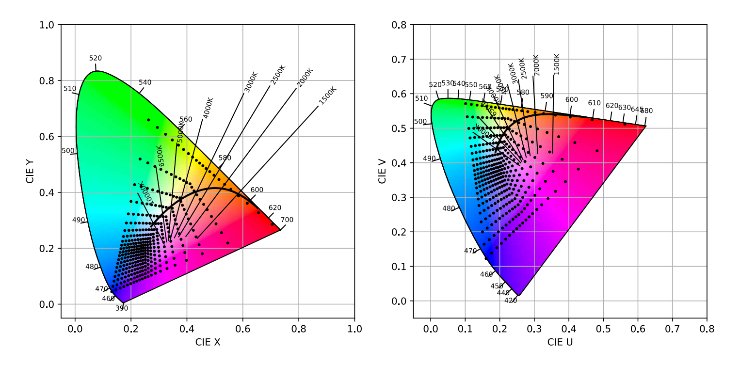
CIE XY and CIE UV space plots of color coordinates
For more information on the CIE and CIY values, refer to the CIE 1931 Color Space Wiki Page.
Example 2: Basic Lux Readings
This example measures the lux readings of the surrounding environment. To find Example 2, go to File > Examples > SparkFun Color Sensor OPT4048 > example2_BasicLuxSensing:
Finding Example 2
Alternatively, you can expand the link below and copy and paste the code into a shiny new Arduino sketch:
Example 2: Basic Lux Sensing Arduino Code
/*
Example 2 - Basic Lux Sensing

This example shows the basic operation of the OPT4048 Color Sensor
for sensing light intensity.

Written by Elias Santistevan @ SparkFun Electronics, July 2023

Products:
    Qwiic 1x1: https://www.sparkfun.com/products/22638
    Qwiic Mini: https://www.sparkfun.com/products/22639

Repository:
    https://github.com/sparkfun/SparkFun_OPT4048_Arduino_Library

SparkFun code, firmware, and software is released under the MIT
License (http://opensource.org/licenses/MIT).
*/

#include "SparkFun_OPT4048.h"
#include <Wire.h>

SparkFun_OPT4048 myColor;

void setup()
{
    Serial.begin(115200);
    Serial.println("OPT4048 Example 2 Basic Lux Sensing.");

    Wire.begin();

    if (!myColor.begin()) {
        Serial.println("OPT4048 not detected- check wiring or that your I2C address is correct!");
        while (1) ;
    }

    myColor.setBasicSetup();

    Serial.println("Ready to go!");
}


void loop()
{
    Serial.print("Lux:");
    Serial.print(myColor.getLux());
    // Delay time is set to the conversion time * number of channels
    // You only need one channel for sensing light intensity @ 200ms conversion time = 200ms.
    delay(200);
}
Make sure you've selected the correct board and port in the Tools menu and then hit the upload button. Once the code has finished uploading, go ahead and open a Serial Monitor. You should see something similar to the following.

Example 2 Output
Lux values will be measured anywhere from 2.15 mlux to 144 klux. Measurements here start at my general office lighting, and then I put my finger over the sensor.
Example 3: Basic Color Warmth
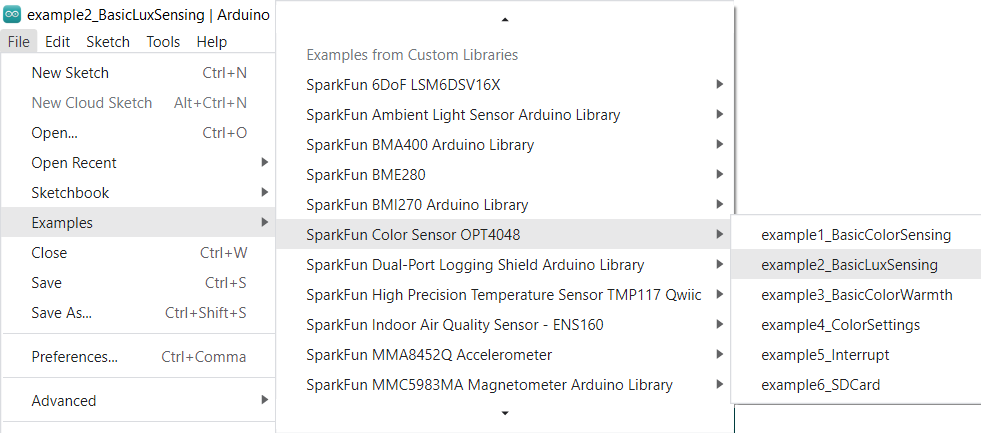
This example measures the basic color warmth. To find Example 3, go to File > Examples > SparkFun Color Sensor OPT4048 > example3_BasicColorWarmth:

Finding Example 3
Alternatively, you can expand the link below and copy and paste the code into a shiny new Arduino sketch:
Example 3: Basic Color Warmth Arduino Code
/*
Example 3 - Color Warmth

This example shows how to retrieve the Corelated Color Temperature (CCT) from the OPT4048.
If you need more information on CCT, check out this Wikipedia article:
https://en.wikipedia.org/wiki/Correlated_color_temperature

Written by Elias Santistevan @ SparkFun Electronics, July 2023

Products:
    Qwiic 1x1: https://www.sparkfun.com/products/22638
    Qwiic Mini: https://www.sparkfun.com/products/22639

Repository:
    https://github.com/sparkfun/SparkFun_OPT4048_Arduino_Library

SparkFun code, firmware, and software is released under the MIT
License (http://opensource.org/licenses/MIT).
*/

#include "SparkFun_OPT4048.h"
#include <Wire.h>

SparkFun_OPT4048 myColor;

void setup()
{
    Serial.begin(115200);
    Serial.println("OPT4048 Example 3 Basic Color Warmth.");

    Wire.begin();

    if (!myColor.begin()) {
        Serial.println("OPT4048 not detected- check wiring or that your I2C address is correct!");
        while (1) ;
    }

    myColor.setBasicSetup();

    Serial.println("Ready to go!");
}


void loop()
{
    Serial.print("Color Warmth: ");
    Serial.print(myColor.getCCT());
    Serial.println("K");
    // Delay time is set to the conversion time * number of channels
    // You need three channels for color sensing @ 200ms conversion time = 600ms.
    delay(600);
}
Make sure you've selected the correct board and port in the Tools menu and then hit the upload button. Once the code has finished uploading, go ahead and open a Serial Monitor. You should see something similar to the following.
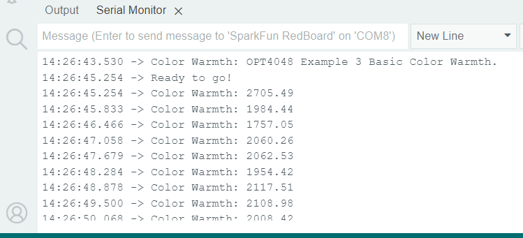
Example 3 Output
Color warmth addresses the perceived "feel" of the color. Color temperatures over 5000 K are called "cool colors" (bluish), while lower color temperatures (2700–3000 K) are called "warm colors" (yellowish).
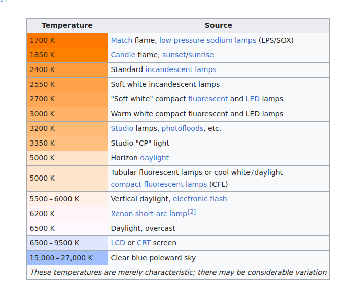
For more information on color temperature values, refer to the Color temperature Wiki Page.
Example 4: Color Settings
The color settings example lists the conversion times for each channel. In a nutshell, the longer the conversion time, the more accurate the read values. To find Example 4, go to File > Examples > SparkFun Color Sensor OPT4048 > example4_ColorSettings:
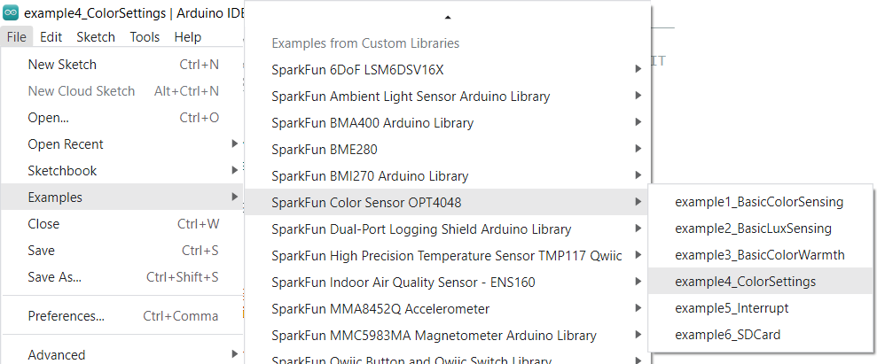
Finding Example 4
Alternatively, you can expand the link below and copy and paste the code into a shiny new Arduino sketch:
Example 4: Basic Color Senttings
/*
Example 4 - This example shows some of the examples.

This example shows the various settings for the OPT4048 and how to set and read them.

Written by Elias Santistevan @ SparkFun Electronics, July 2023

Products:
    Qwiic 1x1: https://www.sparkfun.com/products/22638
    Qwiic Mini: https://www.sparkfun.com/products/22639

Repository:
    https://github.com/sparkfun/SparkFun_OPT4048_Arduino_Library

SparkFun code, firmware, and software is released under the MIT
License (http://opensource.org/licenses/MIT).
*/

#include "SparkFun_OPT4048.h"
#include <Wire.h>

SparkFun_OPT4048 myColor;

void setup()
{
    Serial.begin(115200);
    Serial.println("OPT4048 Example 4 OPT4048 Advanced Settings");

    Wire.begin();

    if (!myColor.begin()) {
        Serial.println("OPT4048 not detected- check wiring or that your I2C address is correct!");
        while (1) ;
    }


    /////////////////////////////////////////////General Settings
    /*
     RANGE_2KLUX2,
     RANGE_4KLUX5,
     RANGE_9LUX,
     RANGE_18LUX,
     RANGE_36LUX,
     RANGE_72LUX,
     RANGE_144LUX,
     RANGE_AUTO
     A higher color range will result in a lower resolution.
     The RANGE_AUTO option will automatically select the best
     range for the current light conditions.
    */
    myColor.setRange(RANGE_2KLUX2);
    Serial.print("Range set to: ");
    Serial.println(myColor.getRange());
    //

    /*
     CONVERSION_TIME_600US,
     CONVERSION_TIME_1MS,
     CONVERSION_TIME_1MS8,
     CONVERSION_TIME_3MS4,
     CONVERSION_TIME_6MS5,
     CONVERSION_TIME_12MS7,
     CONVERSION_TIME_25MS,
     CONVERSION_TIME_50MS,
     CONVERSION_TIME_100MS,
     CONVERSION_TIME_200MS,
     CONVERSION_TIME_400MS,
     CONVERSION_TIME_800MS
     A higher conversion time will result in more precise readings.
     For color sensing, having the highest converstion time is suggested.
    */
    myColor.setConversionTime(CONVERSION_TIME_800MS);
    Serial.print("Conversion time set to:");
    Serial.println(myColor.getConversionTime());

    /*
     OPERATION_MODE_POWER_DOWN,
     OPERATION_MODE_AUTO_ONE_SHOT,
     OPERATION_MODE_ONE_SHOT,
     OPERATION_MODE_CONTINUOUS
    */
    myColor.setOperationMode(OPERATION_MODE_CONTINUOUS);
    Serial.print("Conversion time set to:");
    Serial.println(myColor.getOperationMode());


   // The Quick wake setting changes the behavior of the chip while in power down mode:
   // Not all of the circuitry will be powered down.
   // myColor.setQwake();
    Serial.println("Ready to go!");
}


void loop()
{
    Serial.print("CIEx: ");
    Serial.println(myColor.getCIEx());
    Serial.print("CIEy: ");
    Serial.println(myColor.getCIEy());
    Serial.print("CCT: ");
    Serial.println(myColor.getCCT());
    // Delay time is set to the conversion time * number of channels
    // You need three channels for color sensing @ 800ms conversion time = 3200ms.
    delay(3200);
}
Make sure you've selected the correct board and port in the Tools menu and then hit the upload button. Once the code has finished uploading, go ahead and open a Serial Monitor. You should see something similar to the following.
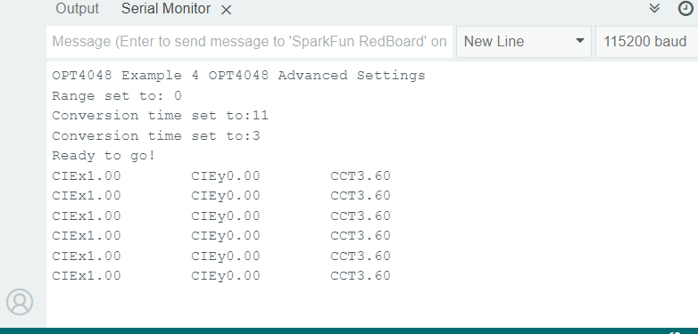
Example 4 Output
Example 5: Interrupt
The OPT4048 Color Sensor can be triggered by an interrupt if desired. Example 5 shows a simple setup case. To find Example 5, go to File > Examples > SparkFun Color Sensor OPT4048 > example5_Interrupt:

Finding Example 5
Alternatively, you can expand the link below and copy and paste the code into a shiny new Arduino sketch:
Example 5: Interrupt
/*
Example 5 - Interrupts

This example shows the various interrupt settings and their uses.

Written by Elias Santistevan @ SparkFun Electronics, July 2023

Products:
    Qwiic 1x1: https://www.sparkfun.com/products/22638
    Qwiic Mini: https://www.sparkfun.com/products/22639

Repository:
    https://github.com/sparkfun/SparkFun_OPT4048_Arduino_Library

SparkFun code, firmware, and software is released under the MIT
License (http://opensource.org/licenses/MIT).
*/

#include "SparkFun_OPT4048.h"
#include <Wire.h>

SparkFun_OPT4048 myColor;

int interruptPin = 3;

void setup()
{
    Serial.begin(115200);
    Serial.println("OPT4048 Example 5 - Interrupts.");

    pinMode(interruptPin, INPUT);

    Wire.begin();

    if (!myColor.begin()) {
        Serial.println("OPT4048 not detected- check wiring or that your I2C address is correct!");
        while (1) ;
    }

    // See Color Settings Example for functions for setting
    // converstion time, range, and mode.
    myColor.setBasicSetup();

    // Basic usage: if interrupt is set to latched mode
    //myColor.setIntLatch();
    myColor.setIntMechanism(INT_DR_ALL_CHANNELS);

    // Select the channel that will fire the interrupt
    // Lux values are generated in Channel One.
    //myColor.setThresholdChannel(THRESH_CHANNEL_CH1);

    // Change the interrupt direction to active HIGH.
    //myColor.setIntActiveHigh();

    // Change the interrupt to an INPUT to trigger measurements
    // set operation mode to one shot mode in this case.
    // myColor.setIntInput();

    Serial.println("Ready to go!");
}


void loop()
{
    if(digitalRead(interruptPin) == LOW)
    {
        Serial.print("CIEx: ");
        Serial.println(myColor.getCIEx());
        Serial.print("CIEy: ");
        Serial.println(myColor.getCIEy());
    }
    // Delay time is set to the conversion time * number of channels
    // You need three channels for color sensing @ 200ms conversion time = 600ms.
    delay(200);
}
The hardware setup should look something like this:

Example 5 Setup
The example code sets the interrupt pin as Pin 3, but if you change the code, you'll need to change the hardware setup.
Make sure you've selected the correct board and port in the Tools menu and then hit the upload button. Once the code has finished uploading, go ahead and open a Serial Monitor.
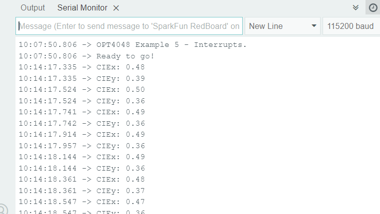
Example 5 Output
The output here sits at "Ready to go" until pin 3 is pulled low, then the output starts to roll by.