/*Super HeadphonesSparkFun ElectronicsPete LewisSeptember 2023Using an ESP32 Thing Plus and a WM8960 Audio Codec,This project enables you to create your own wireless headphones (aka BT).It also alows you to mix in a pair of ambient microphones!Read the tutorial here:https://docs.sparkfun.com/SuperHeadphones/This code utilized Paul Schatzmann's ESP32-A2DP library to make all the wireless audio (BT) functionality happen. Big thank you to Paul Schatzmann and the many others who have contributed to that library!Download here: https://github.com/pschatzmann/ESP32-A2DP Do you like this open source code? Help support SparkFun. Buy a board! SparkFun Audio Codec Breakout - WM8960 (Qwiic) https://www.sparkfun.com/products/21250 SparkFun Thing Plus - ESP32 WROOM (USB-C) https://www.sparkfun.com/products/20168This program is distributed in the hope that it will be useful,but WITHOUT ANY WARRANTY; without even the implied warranty ofMERCHANTABILITY or FITNESS FOR A PARTICULAR PURPOSE. See theGNU General Public License for more details.You should have received a copy of the GNU General Public Licensealong with this program. If not, see <http://www.gnu.org/licenses/>.*/#include<Wire.h>#include<SparkFun_WM8960_Arduino_Library.h> // CTRL+Click here to get the library: http://librarymanager/All#SparkFun_WM8960WM8960codec1;#include"BluetoothA2DPSink.h" // To manually install, download here: https://github.com/pschatzmann/ESP32-A2DPBluetoothA2DPSinka2dp_sink;//// Iot Redboard//#define I2S_WS 16//#define I2S_SD 25//#define I2S_SDO 17//#define I2S_SCK 14// ESP32 Thing Plus C#define I2S_WS 13#define I2S_SD 27#define I2S_SDO 14#define I2S_SCK 32// Use I2S Processor 0#define I2S_PORT I2S_NUM_0// Define input buffer length#define bufferLen 64int16_tsBuffer[bufferLen];intpgaGain1=25;intpgaGain1_prev=0;#define NUM_OF_READINGS 20longuserInputA0;intuserInputArray[NUM_OF_READINGS]={};// used to make a rolling average of readings on ADC inputintarrayPos=0;#define PGA_GAIN_SETTING_MAX 32 // don't really need more than this on the PGA, so let's put a max on it so no one gets too crazy.voidsetup(){Serial.begin(115200);Serial.println(" ");Wire.begin();Wire.setClock(100000);if(codec1.begin()==false)//Begin communication over I2C{Serial.println("The codec 1 did not respond. Please check wiring.");while(1);//Freeze}Serial.println("Codec1 is connected properly.");codec1_setup();// Set up I2Si2s_install();i2s_setpin();a2dp_sink.start("SuperHeadphones");}voidloop(){// Read the volumet potentiometer to set the volume of the ambient mics.// Every loop:// - take a reading and put it into the array// - increment position// - loop back position to start of array // - when we reach the end take all readings in array, and create a rolling average.userInputArray[arrayPos]=analogRead(A0);arrayPos+=1;if(arrayPos>NUM_OF_READINGS)arrayPos=0;inttotal=0;for(inti=0;i<NUM_OF_READINGS;i++)total+=userInputArray[i];userInputA0=total/NUM_OF_READINGS;// map it from 0-4096, to a value that is acceptable in the pga gain (0-63)// 0-63, (0 = -17.25dB) <<-- 0.75dB steps -->> (23 = +0dB)...(63 = +30dB)pgaGain1=map(userInputA0,0,4096,PGA_GAIN_SETTING_MAX,0);if(pgaGain1!=pgaGain1_prev){codec1.setLINVOL(pgaGain1);codec1.setRINVOL(pgaGain1);Serial.print("pgaGain1: ");Serial.println(pgaGain1);}pgaGain1_prev=pgaGain1;delay(10);}voidcodec1_setup(){// General setup neededcodec1.enableVREF();codec1.enableVMID();//codec1.enableMicBias();// WM8960_MIC_BIAS_VOLTAGE_0_9_AVDD (0.9*AVDD) or// WM8960_MIC_BIAS_VOLTAGE_0_65_AVDD (0.65*AVDD)//codec1.setMicBiasVoltage(WM8960_MIC_BIAS_VOLTAGE_0_9_AVDD);// setup signal flow to the ADCcodec1.enableLMIC();codec1.enableRMIC();// connect from INPUT1 to "n" (aka inverting) inputs of PGAs.codec1.connectLMN1();codec1.connectRMN1();// disable mutes on PGA inputs (aka INTPUT1)codec1.disableLINMUTE();codec1.disableRINMUTE();// set input boosts to get inputs 1 to the boost mixerscodec1.setLMICBOOST(WM8960_MIC_BOOST_GAIN_0DB);// 0 = 0dBcodec1.setRMICBOOST(WM8960_MIC_BOOST_GAIN_0DB);// 0 = 0dBcodec1.pgaLeftNonInvSignalSelect(WM8960_PGAL_VMID);// for single ended input on LIN1codec1.pgaRightNonInvSignalSelect(WM8960_PGAL_VMID);// for single ended input on RIN1//codec1.enablePgaZeroCross();codec1.connectLMIC2B();codec1.connectRMIC2B();// enable boost mixerscodec1.enableAINL();codec1.enableAINR();// enable output mixerscodec1.enableLOMIX();codec1.enableROMIX();// Enable bypass connection from Left INPUT3 to Left output mixer, note, the// default gain on this input (LI2LOVOL) is -15dBcodec1.enableLI2LO();codec1.enableRI2RO();// Sets volume control between "left input" to "left output mixer"codec1.setLI2LOVOL(WM8960_OUTPUT_MIXER_GAIN_0DB);codec1.setRI2ROVOL(WM8960_OUTPUT_MIXER_GAIN_0DB);// LB2LO (booster to output mixer (analog bypass)codec1.enableLB2LO();codec1.enableRB2RO();// connect from DAC outputs to output mixercodec1.enableLD2LO();codec1.enableRD2RO();// set gainstage between booster mixer and output mixer// for this loopback example, we are going to keep these as low as they gocodec1.setLB2LOVOL(WM8960_OUTPUT_MIXER_GAIN_0DB);// 0 = -21dBcodec1.setRB2ROVOL(WM8960_OUTPUT_MIXER_GAIN_0DB);// 0 = -21dB// CLOCK STUFF, These settings will get you 44.1KHz sample rate, and class-d freq at 705.6kHzcodec1.enablePLL();// needed for class-d amp clockcodec1.setPLLPRESCALE(WM8960_PLLPRESCALE_DIV_2);codec1.setSMD(WM8960_PLL_MODE_FRACTIONAL);codec1.setCLKSEL(WM8960_CLKSEL_PLL);codec1.setSYSCLKDIV(WM8960_SYSCLK_DIV_BY_2);codec1.setBCLKDIV(4);codec1.setDCLKDIV(WM8960_DCLKDIV_16);codec1.setPLLN(WM8960_DCLKDIV_16);codec1.setPLLK(0x86,0xC2,0x26);// PLLK=86C226h//codec1.set_ADCDIV(0); // default is 000 (what we need for 44.1KHz), so no need to write this.//codec1.set_DACDIV(0); // default is 000 (what we need for 44.1KHz), so no need to write this.codec1.setWL(WM8960_WL_16BIT);codec1.enablePeripheralMode();//codec1.enableMasterMode();//codec1.set_ALRCGPIO(); // note, should not be changed while ADC is enabled.// enable ADCs and DACscodec1.enableAdcLeft();codec1.enableAdcRight();codec1.enableDacLeft();codec1.enableDacRight();codec1.disableDacMute();//codec1.enableLoopBack(); // Loopback sends ADC data directly into DACcodec1.disableLoopBack();codec1.disableDacMute();// default is "soft mute" on, so we must disable mute to make channels activecodec1.enableHeadphones();//codec1.enableSpeakers();codec1.enableOUT3MIX();// provides VMID as buffer for headphone ground//codec1.enableSpeakerZeroCross();Serial.println("Volume set to +0dB");//codec1.setSpeakerVolume(120);codec1.setHeadphoneVolumeDB(0.00);//codec1.enable3d();Serial.println("Codec 1 Setup complete. Listen to left/right INPUT1 on Speaker outputs.");delay(10);codec1.setLINVOL(23);codec1.setRINVOL(23);}voidi2s_install(){// Set up I2S Processor configurationstatici2s_config_ti2s_config={.mode=(i2s_mode_t)(I2S_MODE_MASTER|I2S_MODE_TX),.sample_rate=44100,// Updated automatically by A2DP.bits_per_sample=(i2s_bits_per_sample_t)16,.channel_format=I2S_CHANNEL_FMT_RIGHT_LEFT,.communication_format=(i2s_comm_format_t)(I2S_COMM_FORMAT_STAND_I2S),.intr_alloc_flags=0,// Default interrupt priority.dma_buf_count=8,.dma_buf_len=64,.use_apll=true,.tx_desc_auto_clear=true// Avoiding noise in case of data unavailability};a2dp_sink.set_i2s_config(i2s_config);}voidi2s_setpin(){// Set I2S pin configurationi2s_pin_config_tmy_pin_config={.bck_io_num=I2S_SCK,.ws_io_num=I2S_WS,.data_out_num=I2S_SDO,.data_in_num=I2S_PIN_NO_CHANGE};a2dp_sink.set_pin_config(my_pin_config);}
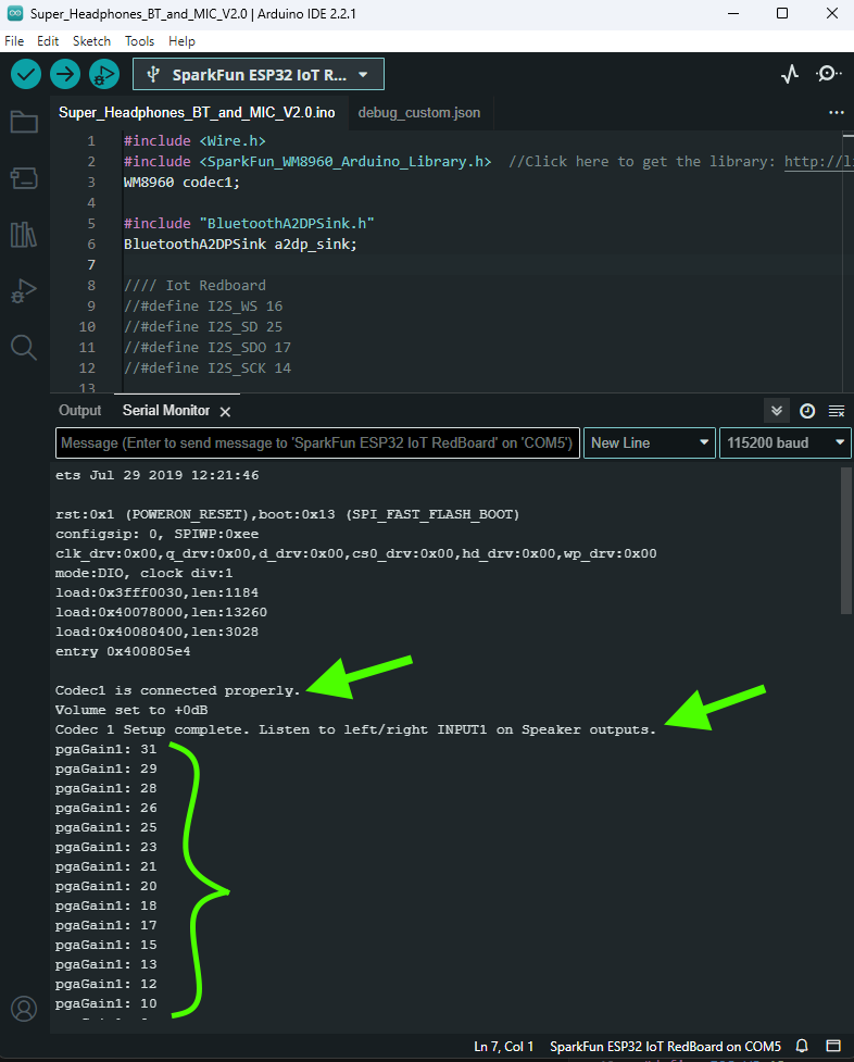
Select your board in the Tools menu (in our case ESP32 Thing Plus) and the correct Port it enumerated on and click "Upload". After uploading the code, open the Serial Monitor or terminal emulator of your choice with the baud rate set to 115200. You should see the following message pop up. And then as you turn the volume potentiometer, the setting value will be printed to the terminal.
If you see the above messages in your terminal, then you should be ready to try out some listening. Put your headphones on and try adjusting the potentiometer. As you turn the knob (clockwise), this will increase the volume level of the microphones.
One way to verify the system is to turn the volume all the way up and gently rub each microphone with your fingertip. You should hear a quiet scratching sound in the corresponding headphone ear speaker.
Note, if you hear a lot of buzzing, it is most likely the USB cable. Try unplugging the USB cable, and powering only from the battery. The battery will be a much quieter power source, and so should not add any noise into the audio signal.
Wireless connection
In addition to the messages sent to the serial terminal, the provided code sets up the ESP32 Thing Plus to be an audio receiver as a bluetooth A2DP Sink.
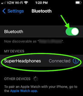
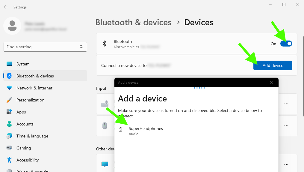
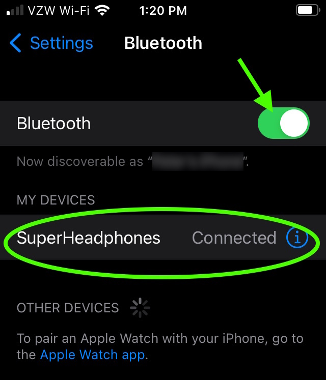
After powering up your headphones, use your PC or cell phone to find a Bluetooth device named "SuperHeadphones".
Connect BT with your PC
Connect to BT with your cell phone
Click Connect. Now you can play audio from your PC program or phone app and listen on your superheadphones!
Note, the volume control for this sound source is controlled by adjusting the setting on your computer or cell phone. The knob on the headphones is only used to adjust the volume of the ambient microphones.
Diving deeper
The provided code for this project is a combination of other Arduino example
sketches. Review these for further information on how each section of the code works.