Hardware Assembly
Important: Read Before Use!
ESD Sensitivity
The mosaic-X5 module is sensitive to ESD. Use a proper grounding system to make sure that the working surface and the components are at the same electric potential.
ESD Precaution
As recommended by the manufacturer, we highly recommend that users take the necessary precautions to avoid damaging their module.
- The Tri-band GNSS RTK breakout board features ESD protection on the USB-C connector and breakout's I/O:
- USB data lines
- I/O PTH pads
- JST connector's pins
- The mosaic-X5 module features internal ESD protection to the
ANT_1antenna input.
-
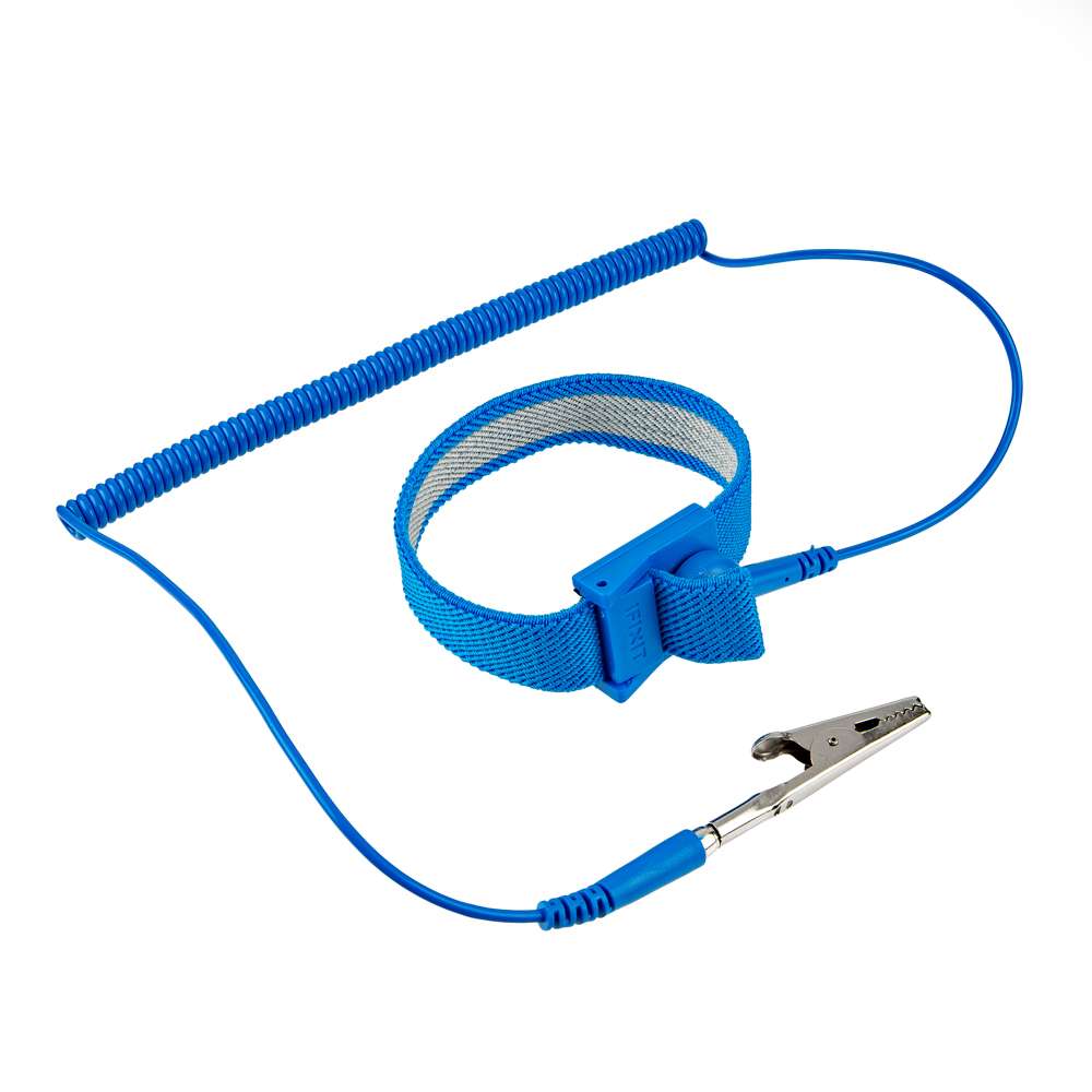
iFixit Anti-Static Wrist Strap
TOL-25572
Active Antenna
Never inject an external DC voltage into the SMA connector for the GPS antenna, as it may damage the mosaic-X5 module. For instance, when using a splitter to distribute the antenna signal to several GNSS receivers, make sure that no more than one output of the splitter passes DC. Use DC-blocks otherwise.
Info
A 3 - 5.5V DC voltage can be applied to the main antenna from the VANT pin, obviating the need for an external antenna supply or bias-tee.
USB Programming
The USB connection is utilized for programming and serial communication. Users only need to plug their Tri-band GNSS RTK breakout board into a computer using a USB-C cable.
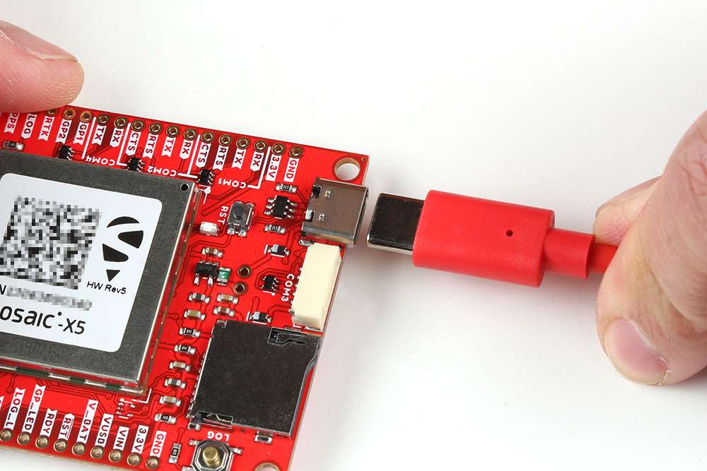
The Tri-band GNSS RTK breakout board with USB-C cable being attached.
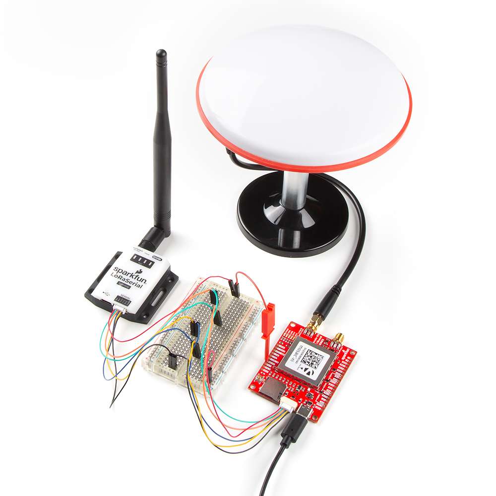
GPS Antenna
In order to receive GNSS signals, users will need to connect a compatible antenna. For the best performance, we recommend users choose an active, L1/L2/L5 (tri-band) GNSS antenna and utilize a low-loss cable.

Attaching a GPS antenna to the SMA connector on the Tri-band GNSS RTK breakout board.
SD Card
An µSD card slot is available for users to log and store data, locally on the board. Users, will need to insert a compatible SD card and configure the mosaic-X5 module for data logging.

Inserting an SD card into the Tri-band GNSS RTK breakout board.
Tip
There are multiple ways to configure and enable data logging to an SD card. However, the simplest method is with the LOG button.
- Pressing the LOG button (< 5s) toggles data logging to the SD card on and off.
- Holding the LOG button for more than 5 seconds (> 5s) and then releasing it, will force the board to:
- Unmount the SD card if it was mounted
- Mount the SD card if it was unmounted
For more information, please reference the SD Card Slot section.
JST Connector
The JST connector on the Tri-band GNSS RTK board, breaks out the COM3 UART port of the mosaic-X5 module.
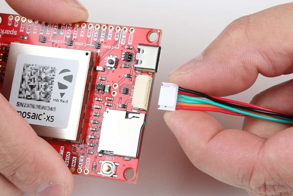
Connecting a cable to the JST connector of the Tri-band GNSS RTK breakout board.
Connecting a Radio
Radio Transceivers
In most circumstances, users will utilize the JST connector to interface with one of our radio transceivers for RTK correction data:
-
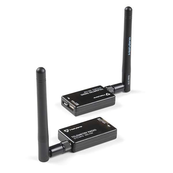
SiK Telemetry Radio V3 - 915MHz, 100mW
WRL-19032 -
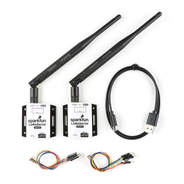
SparkFun LoRaSerial Kit - 915MHz (Enclosed)
WRL-20029
Pin Connections
When connecting the Tri-band GNSS RTK breakout board to one of our radio transceivers, users need to be aware of the pin connections between the products; as their pin layout is mirrored on each connector. Although the labels on each device may vary, their pins will operate exactly the same; with the exception of the input voltage ranges.
| Pin Number |
1 (Left Side) |
2 | 3 | 4 | 5 |
6 (Right) |
|---|---|---|---|---|---|---|
| Label |
V - Triband 5V - Radios |
RX - Triband/SiK RXI - LoRaSerial |
TX - Triband/SiK TXO - LoRaSerial |
C - Triband CTS - Radios |
R - Triband RTS - Radios |
G - Triband GND - Radios |
| Function |
Voltage Input - Triband: 3.5 to 5.5V - SiK: 5V - LoRaSerial: 3.3 to 5V |
UART - Receive | UART - Transmit |
Flow Control Clear-to-Send |
Flow Control Ready-to-Send |
Ground |
Pin Connections
-
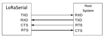
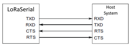
When connecting the Tri-band GNSS RTK breakout board to either of the radios, the pin connections should follow the table below. If the flow control is not enabled, the only the
RX,TX, andGNDpins are utilized.Triband RX TX RTS CTS GND Radio TX RX CTS RTS GND -
As documented in the LoRaSerial product manual, the pin connections between a host system (i.e. Tri-band GNSS RTK breakout board) and the LoRaSerial Kit radio is outlined in the image below.
The COMports on the Tri-band GNSS RTK breakout board.
Wiring Connections
Users have several options for wiring up these two products. Without creating a custom cable assembly, we recommend utilizing our breadboard cable along with any breadboard or F/F jumper wires.
-
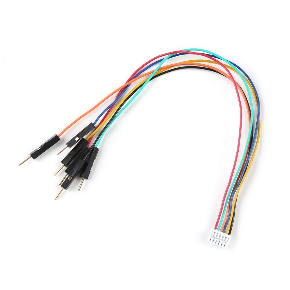
Breadboard to JST-GHR-06V Cable - 6-Pin x 1.25mm Pitch (For LoRaSerial)
CAB-23353 -
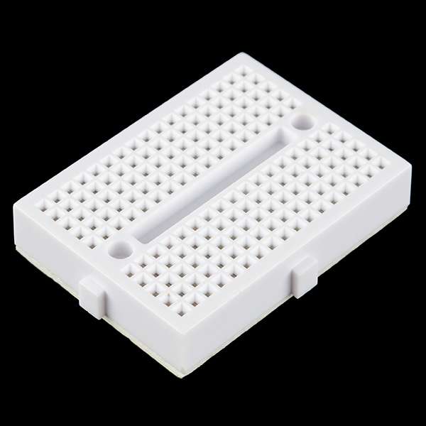
Breadboard - Mini Modular (White)
PRT-12043
Following the pin connections, outlined in the table above, users can wire up the two devices. In the figures below, a reference diagram for the pin connections of JST connector are provided along with an example setup, using a breadboard. However, users are free to utilize the products/methods that suit their project requirements.
-
Below if a diagram of the pin connections for the 6-pin JST GH connector on the devices that users can reference without having to pull up the datasheet or product manuals.
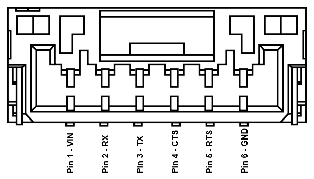
The pin connections of the JST connector on the Tri-band GNSS RTK breakout board. Warning
Please remember that the power pin, is a voltage input and should not be utilized to transfer power between the devices. Users should power their devices separately through the USB connectors on the devices.
-
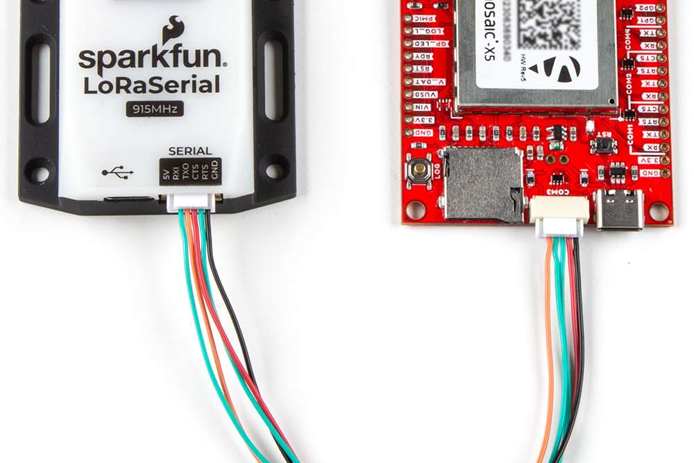
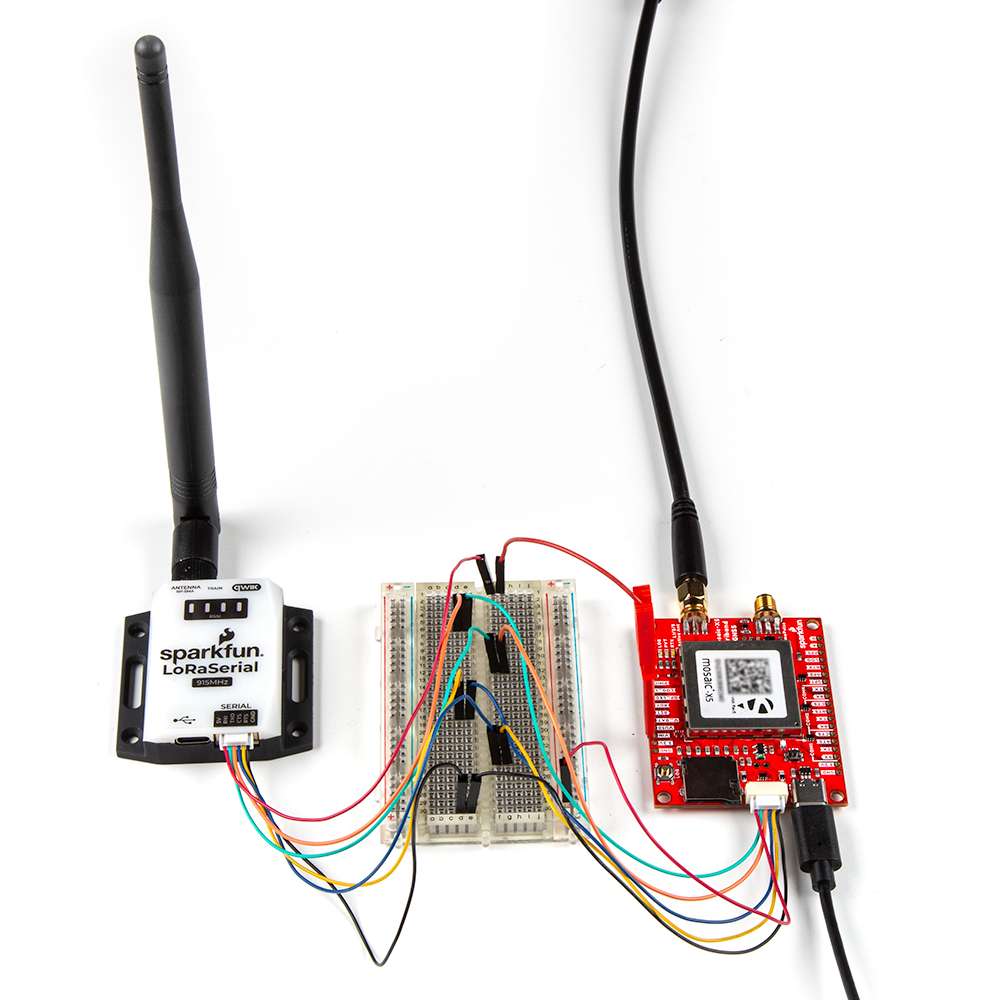
Below, is an example illustrating the Tri-band GNSS RTK breakout board being connected to the LoRaSerial Kit - 915MHz utilizing the breadboard cable and breadboard.
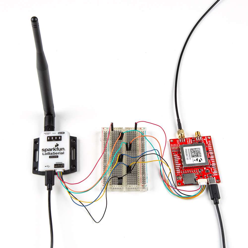
The Tri-band GNSS RTK breakout being connected to the LoRaSerial Kit - 915MHz. In this example, the devices are being powered separately through their USB ports. This is because the devices power pins are configured as voltage inputs. (Click the image to enlarge, users will notice that the power pins are not connected together, unlike the other pins.)
When complete, the setup should appear similar to the figure below.
Pairing Radios
By default, the radios in the LoRaSerial Kit - 915MHz are pre-configured for point-to-point communication and a paired with each other. For instructions on other configurations, please reference the product manual for the LoRaSerial Kit.
Custom Crossover Cable
Users could potentially create their own custom cable from our existing cable assembly. However, this would require delicate dexterity skills as the plastic pins of the harness's connector easily break. Two cable assemblies are required to create a single custom wiring harness (i.e. crossover cable).
-
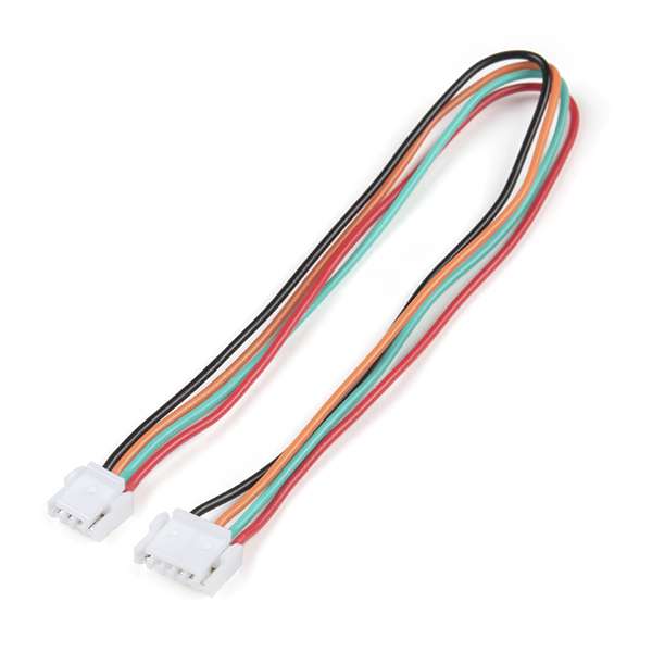
JST-GHR-04V to JST-GHR-06V Cable - 1.25mm pitch
CAB-17239
Following the pin connections, outlined in the table above, users would rewire the cable assembly. Make sure not to exclude the power pin connection; on both devices, that pin is for an input voltage on the JST connector.

Enabling a Voltage Output
Disclaimer
Due to the inherent risks of the modifications below, technical assistance will not be provided nor will refunds or returns be authorized for products with the following modifications.
By proceeding with the instructions below, users acknowledge that they are purposefully circumventing the reverse current protection diode on the board. By doing so, this can potentially expose their computer and any other devices to be permanently damaged. Proceed at your own risk!
Enable Voltage Output
While not recommended, because it bypasses the reverse current protection diode, users can enable a voltage output on the JST connector of the Tri-band GNSS RTK breakout board. Below are two different modifications that users could potentially utilize.
Jumper Pin Modification
The jumper pin modification requires a header to be soldered to the VIN and VUSB pins of the Tri-band GNSS RTK breakout board. Then a 2-pin jumper is utilized to bypass the protection diodes between the two pins. The example in the image below, utilizes a simple straight header. When a jumper is placed on the VIN and VUSB pins, any power that is provided through the USB-C connector of the Tri-band GNSS RTK breakout, will now be connected to the the power pin of the JST connector.

-
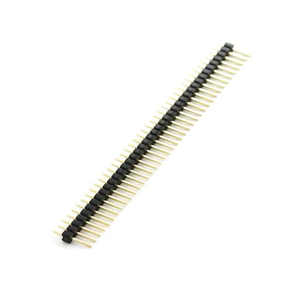
Break Away Headers - Straight
PRT-00116
-
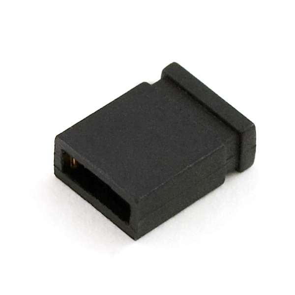
Jumper - 2 Pin
PRT-09044
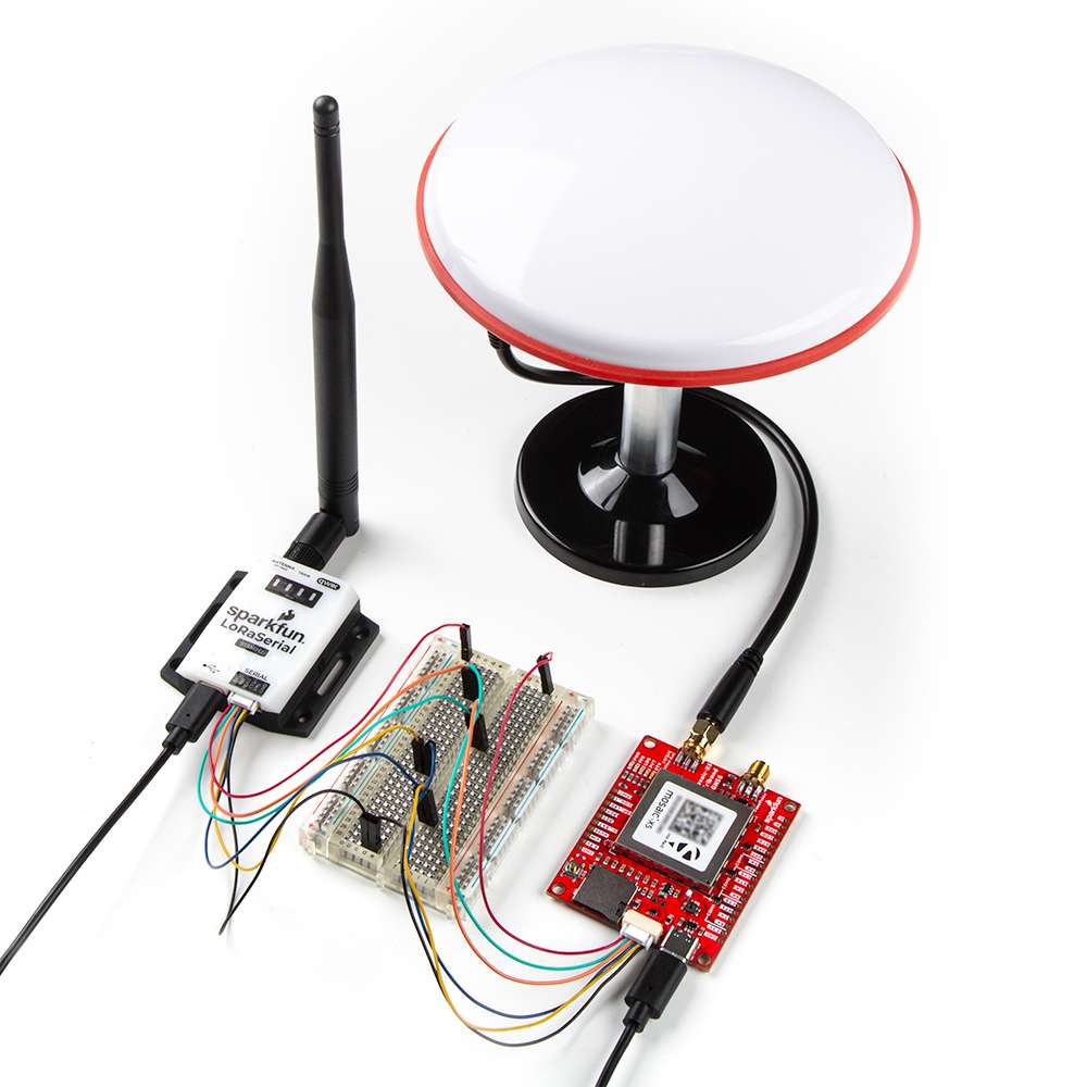
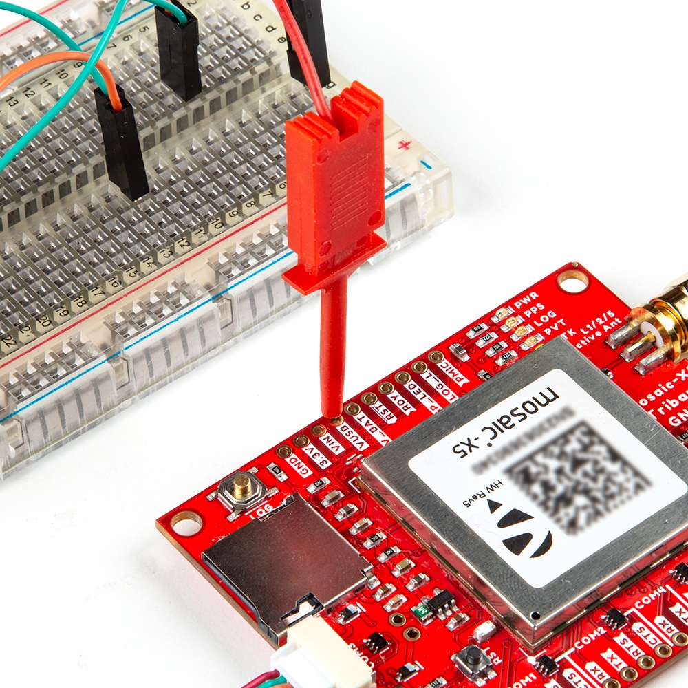
IC-Hook Modification
The IC-hook modification utilizes an IC-hook w/ pigtail to breakout the VUSB pin of the Tri-band GNSS RTK breakout board on a jumper wire.
-
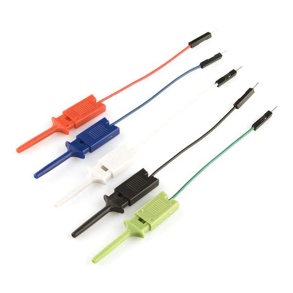
IC Hook with Pigtail
CAB-09741
VUSB pin of the Tri-band GNSS RTK breakout board.
In the example displayed below, IC-hook w/ pigtail connects the VUSB pin of the Tri-band GNSS RTK breakout directly to the 5V pin of the LoRaSerial Kit through the breadboard. (Click the images to enlarge, users will notice that the power pin of the radio is wired directly to the VUSB pin of the Tri-band GNSS RTK breakout board.)
VUSB pin of the Tri-band GNSS RTK breakout board.
Breakout Pins
The PTH pins on the Tri-band GNSS RTK board are broken out into 0.1"-spaced pins on the outer edges of the board.
New to soldering?
If you have never soldered before or need a quick refresher, check out our How to Solder: Through-Hole Soldering guide.
-
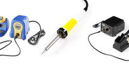
How to Solder: Through-Hole Soldering
When selecting headers, be sure you are aware of the functionality you require.
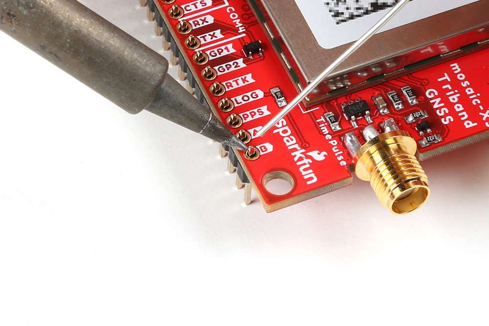
For a more permanent connection, users can solder wires directly to the board.
