Danger
ESD Sensitivity
The mosaic-X5 module is sensitive to ESD. Use a proper grounding system to make sure that the working surface and the components are at the same electric potential.
ESD Precaution
As recommended by the manufacturer, we highly recommend that users take the necessary precautions to avoid damaging their module.
- The Tri-band GNSS RTK breakout board features ESD protection on the USB-C connector and breakout's I/O:
- USB data lines
- I/O PTH pads
- JST connector's pins
- The mosaic-X5 module features internal ESD protection to the
ANT_1antenna input.
-

iFixit Anti-Static Wrist Strap
TOL-25572
Active Antenna
Never inject an external DC voltage into the SMA connector for the GPS antenna, as it may damage the mosaic-X5 module. For instance, when using a splitter to distribute the antenna signal to several GNSS receivers, make sure that no more than one output of the splitter passes DC. Use DC-blocks otherwise.
Info
A 3 - 5.5V DC voltage can be applied to the main antenna from the VANT pin, obviating the need for an external antenna supply or bias-tee.
Introduction
-
mosaic-X5 GNSS Breakout
SKU: GPS-23088

-
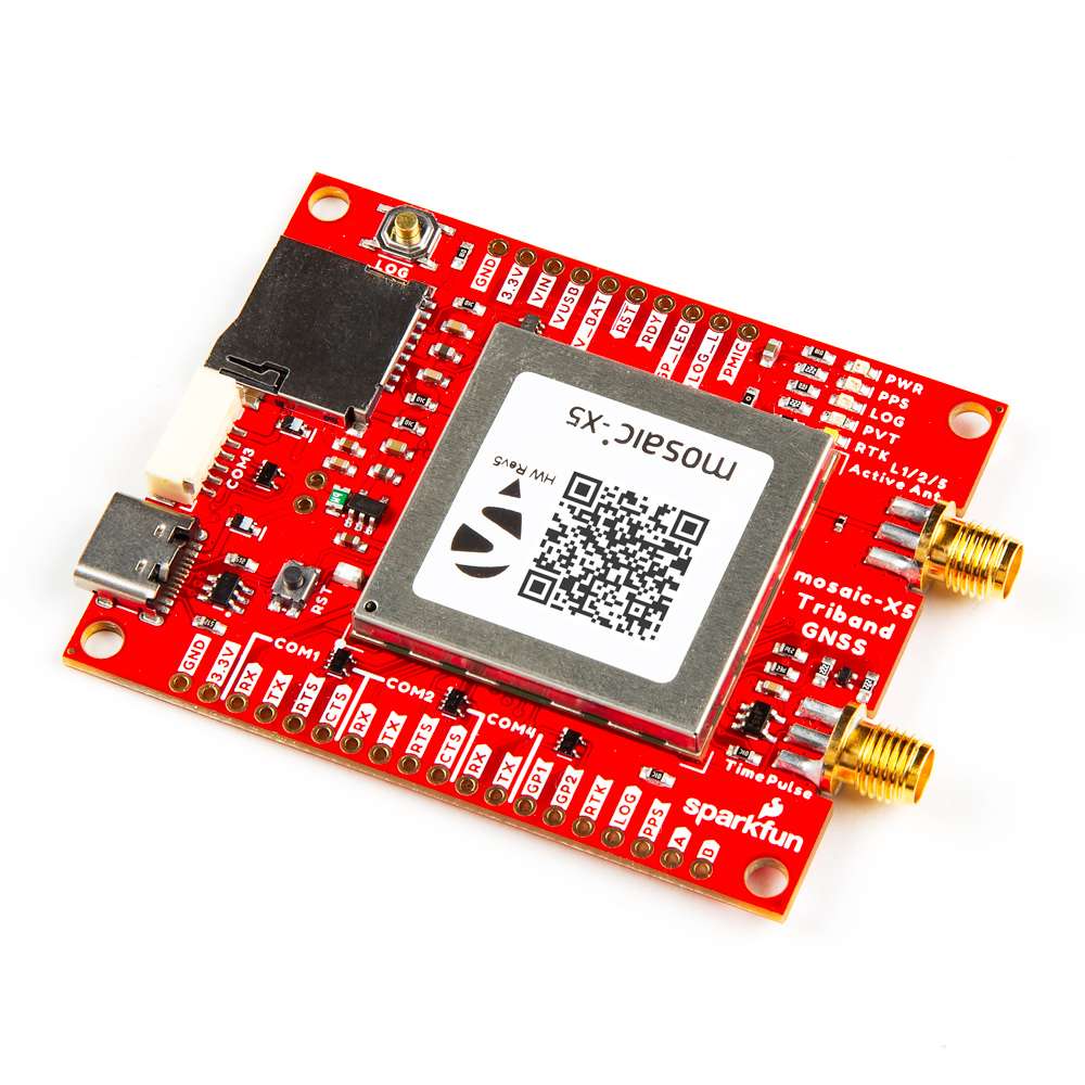
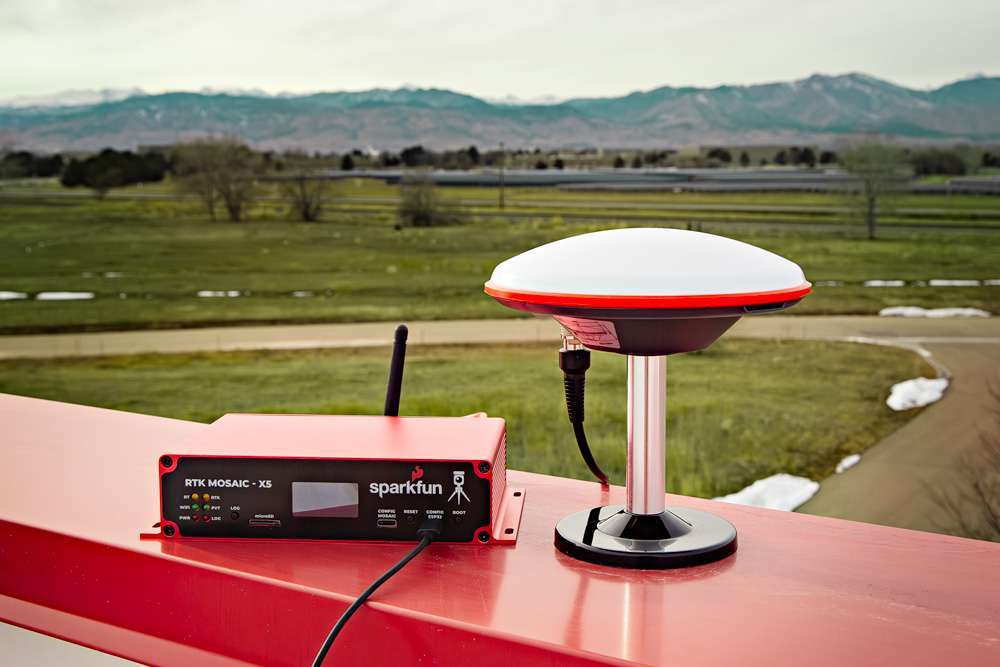
At the heart of the Triband GNSS RTK Breakout is Septentrio's mosaic-X5, their most compact, ultra-low power, multi-band, multi-constellation, high-precision GNSS receiver. The receiver supports the GPS (USA), GLONASS (Russia), Beidou (China), Galileo (Europe), and NavIC (India) constellations, including regional systems (i.e. SBAS and QZSS). With its Real Time Kinematics (RTK) capabilities, the module can achieve a horizontal accuracy of 6mm (~0.25in), vertical accuracy of 1cm (~0.4in) using RTK, and timing precision of 5ns (5 billionths of a second). It also features Septentrio's unique AIM+ technology for interference mitigation and anti-spoofing, ensuring best-in-class reliability and scalable position accuracy.
The mosaic-X5 is a sophisticated chip running an internal web server that can be accessed through the USB interface with a standard browser using a Linux/Windows computer. Septentrio also provides dozens of video tutorials to guide users through the configuration settings of their GNSS receivers utilizing the web interface.
Beyond the capabilities of the mosaic-X5 module, this board is seamless to operate with no programming skills required. Gone are the times when a microcontroller was required to interface with the GNSS receiver and log data to an SD card. The mosaic-X5 Triband GNSS RTK Breakout can start/stop logging data, without a single line of code, just utilizing a simple button.
This breakout board is a perfect middle ground for users who would like to integrate the mosaic-X5 module into a project/enclosure with access to a majority of the module's available pins, similar to Septentrio's developer kit, but in the smaller form factor of their evaluation kit. Or maybe... you just needed a PPS output at a 3.3V logic level. Please, check out the rest ouf our guide for more details on the capabilities of this board (that we couldn't fit in this product description).

Important: Read Before Use!
ESD Sensitivity
The mosaic-X5 module is sensitive to ESD. Use a proper grounding system to make sure that the working surface and the components are at the same electric potential.
ESD Precaution
As recommended by the manufacturer, we highly recommend that users take the necessary precautions to avoid damaging their module.
- The Tri-band GNSS RTK breakout board features ESD protection on the USB-C connector and breakout's I/O:
- USB data lines
- I/O PTH pads
- JST connector's pins
- The mosaic-X5 module features internal ESD protection to the
ANT_1antenna input.
-
iFixit Anti-Static Wrist Strap
TOL-25572
Active Antenna
Never inject an external DC voltage into the SMA connector for the GPS antenna, as it may damage the mosaic-X5 module. For instance, when using a splitter to distribute the antenna signal to several GNSS receivers, make sure that no more than one output of the splitter passes DC. Use DC-blocks otherwise.
Info
A 3 - 5.5V DC voltage can be applied to the main antenna from the VANT pin, obviating the need for an external antenna supply or bias-tee.
Product Comparison
Below is a simple comparison table between our breakout board and Septentrio's development and evaluation kits:
mosaic-X5 Development Kit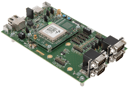
|
mosaic-go Evaluation Kit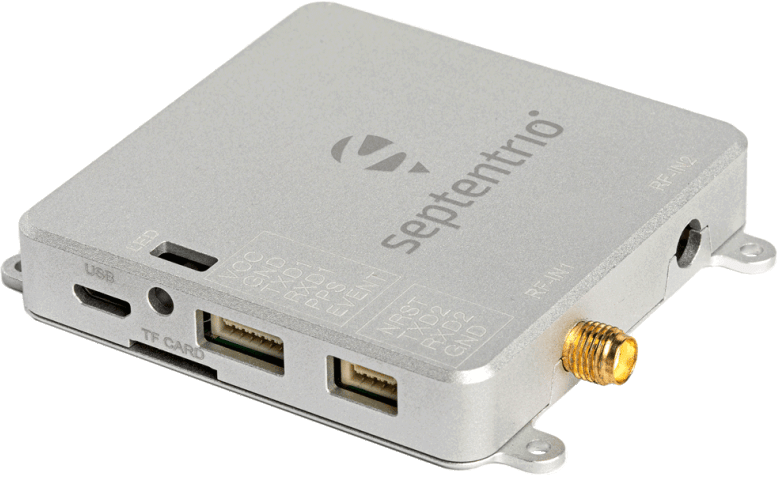
|
mosaic-X5 GNSS Breakout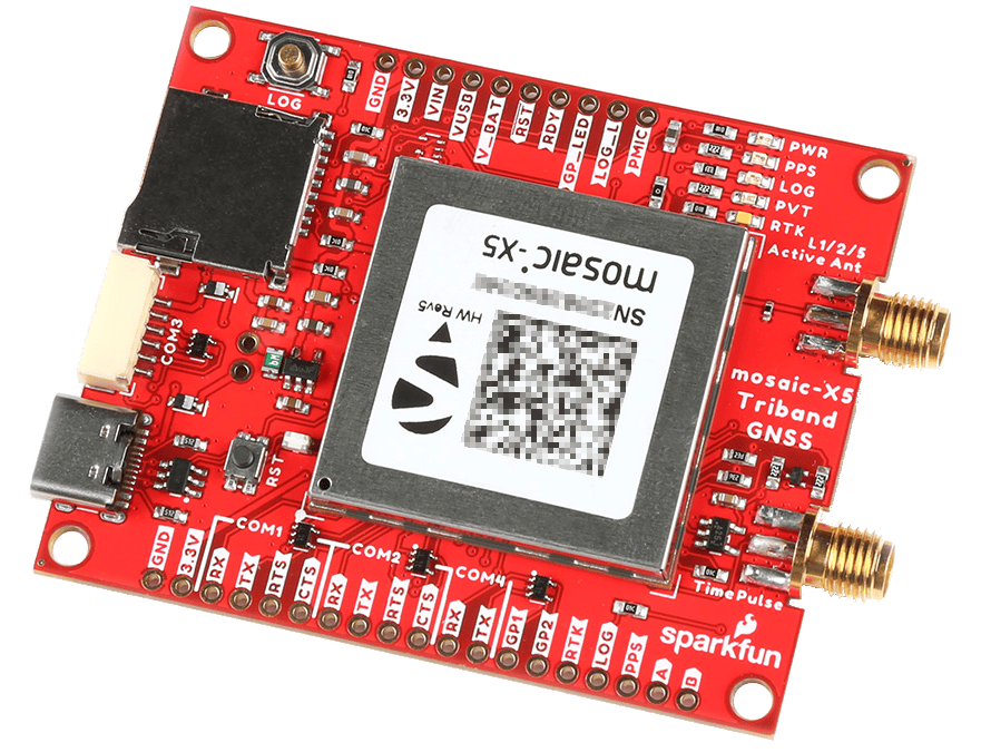
|
RTK mosaic-X5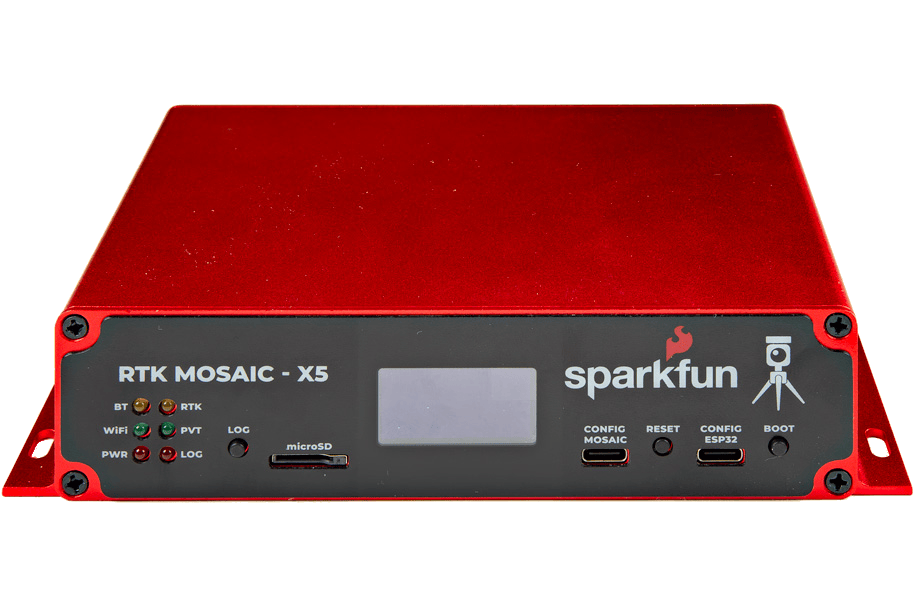
|
mosaic-X5 Flex Module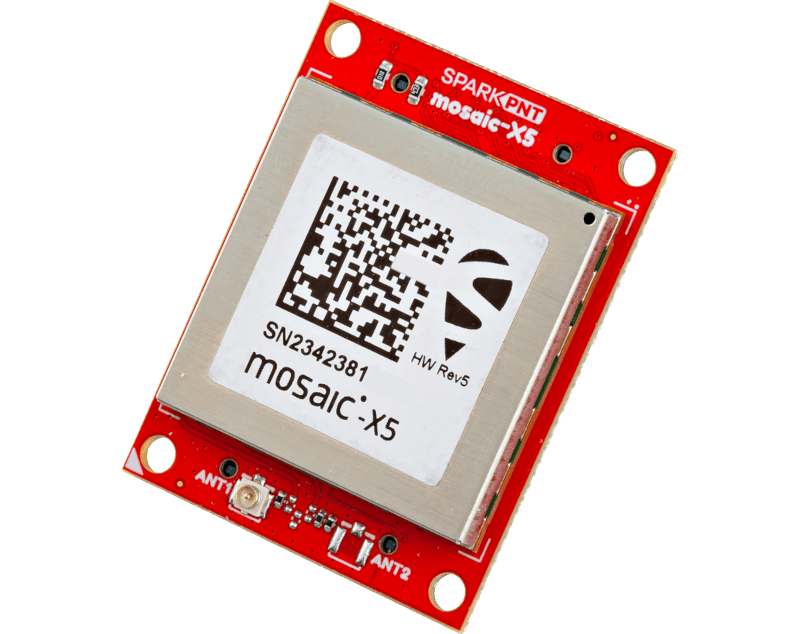
|
SparkPNT RTK Facet mosaic
|
|
|---|---|---|---|---|---|---|
| GNSS Antenna | Dual |
Single (mosaic-X5) Dual (mosaic-H) |
Single | Single | Single | Integrated |
| USB Connector | micro-B | micro-B | Type-C | Type-C | N/A* | Type-C |
| Ethernet |
Yes 10/100 Base-T |
No | No |
Yes 10/100 Base-T |
2x10 Header* | No |
| WiFi | No | No | No |
Yes - Network Bridge 10 Base-T |
No |
Yes - Network Bridge 10 Base-T |
| COM Ports | 4 | 2 | 4 |
1 - mosaic-X5 1 - ESP32 |
4 |
1 - mosaic-X5 1 - ESP32 |
| µSD Card Slot | Yes | Yes | Yes | Yes | 2x10 Header* | Yes |
| Reset/Log Buttons | Yes | No* | Yes | Yes | No | Yes |
| Logic-Level |
1.8V 3.3V |
3.3V | 3.3V |
3.3V 5V |
3.3V | 3.3V |
| PPS Signal | Header Pin | 6-Pin JST Connector | SMA Connector | Screw Terminal | 2x10 Header* | No |
| Enclosure Material | N/A | Metal | N/A | Aluminum | N/A | Plastic |
| Dimensions | N/A | 71 x 59 x 12mm ± 1mm | 70.9 x 50.8 x 8mm |
180.6 x 101.8 x 41mm Enclosure Only |
||
| Weight | N/A | 58g ± 1g | 22.6g |
415.15g Enclosure Only |
mosaic-go Evaluation Kit
The reset pin is exposed on 4-pin JST connector and the log pin is connected to the latch pin of the SD card slot.
mosaic-5 Flex Module
SparkPNT GNSS Flex modules are modular, plug-in boards that utilize a carrier board to access the pins of the GNSS Flex headers.
Required Materials
To get started, users will need a few items. Now some users may already have a few of these items, feel free to modify your cart accordingly.
-
Computer with an operating system (OS) that is compatible with all the software installation requirements (1)
Software Compatibility
The RxTools software suite from Septentrio, automatically installs the required USB-over-Ethernet driver and provides users with an interface for the receiver configuration, monitoring, data logging, and analysis. However, it only appears to be available for Windows and Linux operating systems.
-
USB 3.1 Cable A to C - 3 Foot - Used to interface with the mosaic-X5 GNSS Breakout (2)
- SparkFun Tri-band GNSS RTK Breakout - mosaic-X5 (3)
- GNSS Multi-Band L1/L2/L5 Surveying Antenna
- A list of the compatible GNSS receiver software, is provided on the Septentrio website.
- If your computer doesn't have a USB-A slot, then choose an appropriate cable or adapter.
- For the best performance, use a compatible L1/L2/L5 GNSS antenna.
-
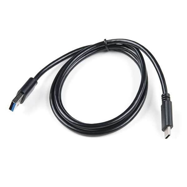
USB 3.1 Cable A to C - 3 Foot
CAB-14743 -
mosaic-X5 (Tri-band + RTK) GNSS Breakout
GPS-23088 -
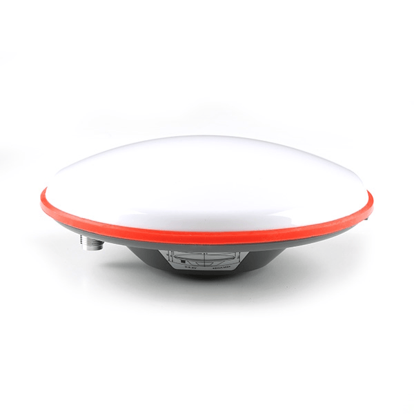
GNSS Multi-Band L1/L2/L5 Surveying Antenna - TNC (SPK6618H)
GPS-21801 -
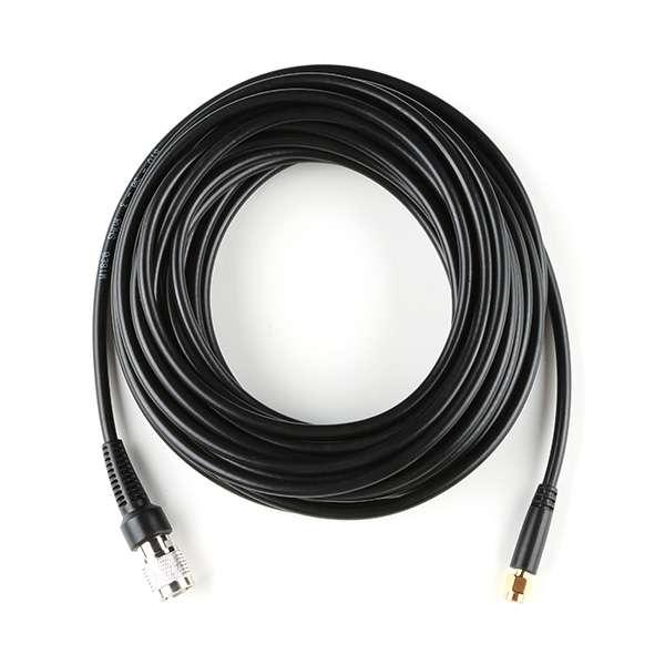
Reinforced Interface Cable - SMA Male to TNC Male (10m)
CAB-21740 -

GNSS Magnetic Antenna Mount - 5/8" 11-TPI
PRT-21257
ESD Protection
The Septentrio mosaic-X5 module is sensitive to ESD. Use a proper grounding system to make sure that the working surface and the components are at the same electric potential.
Warning
As recommended by the manufacturer, we highly recommend that users take the necessary precautions to avoid damaging their module.
-
iFixit Anti-Static Wrist Strap
TOL-25572
Antennas & Accessories
For the best performance, we recommend users choose a compatible L1/L2/L5 (tri-band) GNSS antenna and utilize a low-loss cable. For additional options, please check out the GPS Antenna category of our product catalog.
-
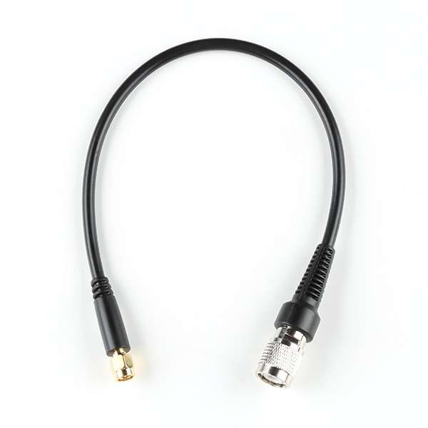
GNSS Multi-Band L1/L2/L5 Surveying Antenna - TNC (SPK6618H)
GPS-21801Adapter Cable
For our TNC antennas, users will need a TNC to SMA adapter cable.
-
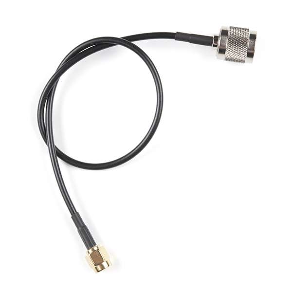
Interface Cable - SMA Male to TNC Male (300mm)
CAB-17833 -
Reinforced Interface Cable - SMA Male to TNC Male (300mm)
CAB-21739 -
Reinforced Interface Cable - SMA Male to TNC Male (10m)
CAB-21740
-
-
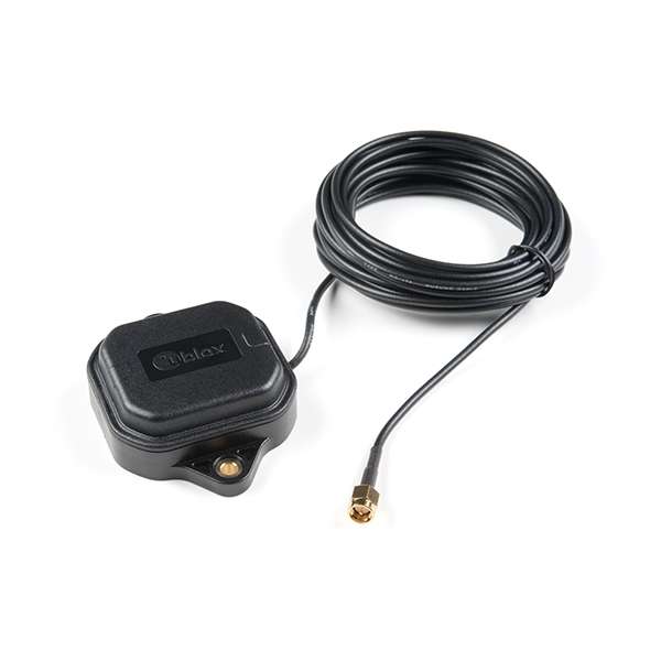
GNSS Multi-Band Magnetic Mount Antenna - 5m (SMA)
GPS-15192Kit Version
We also offer this product in a kit, which includes a ground plate and USB-C cable.
-
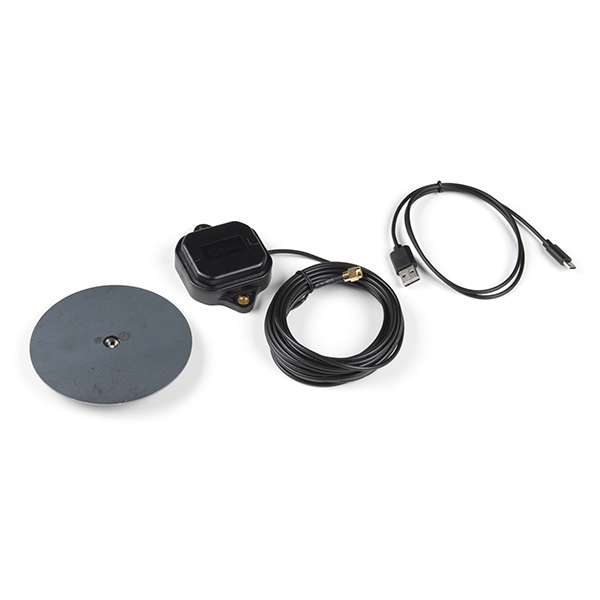
SparkFun GNSS-RTK Accessory Kit
KIT-18293
-
-
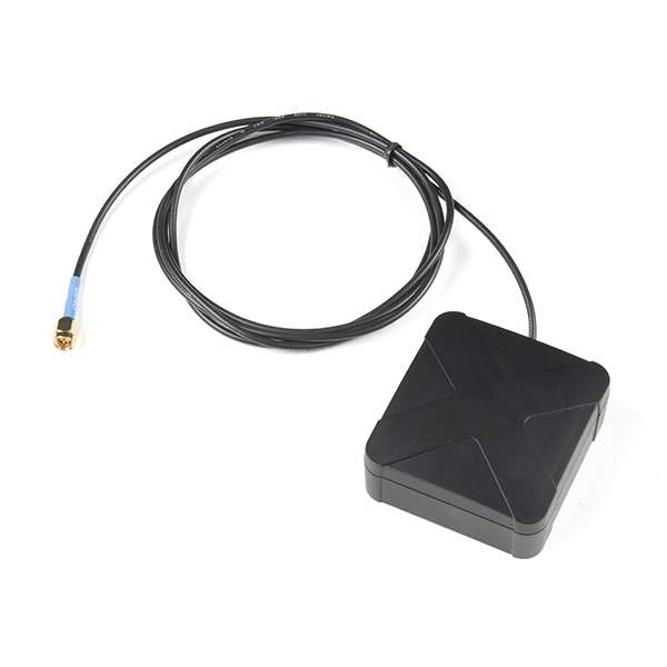
MagmaX2 Active Multiband GNSS Magnetic Mount Antenna - AA.200
GPS-17108
-
GNSS Magnetic Antenna Mount - 5/8" 11-TPI
PRT-212575/8"-11 TPI
This product is meant to be used with our surveying antennas. To mount those antennas to a camera tripod, check out our tripod adapter.
-
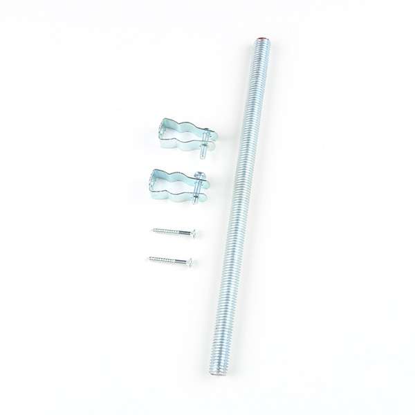
GNSS Antenna Mounting Hardware Kit
KIT-221975/8"-11 TPI
This product is meant to be used with our surveying antennas. To mount those antennas to a camera tripod, check out our tripod adapter.
-

GPS Antenna Ground Plate
GPS-175191/4"-20 TPI
This product is meant to be used with our magnetic antennas and a camera tripod with a standard ¼"-20 UNC camera mounting screw.
Data Logging
The Septentrio mosaic-X5 module is capable of logging data to an µSD card. Please check out the memory cards and accessories in our product catalog.
-
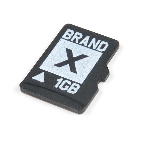
microSD Card - 1GB (Class 4)
COM-15107 -
microSD USB Reader
COM-13004
JST Cable & Transceivers
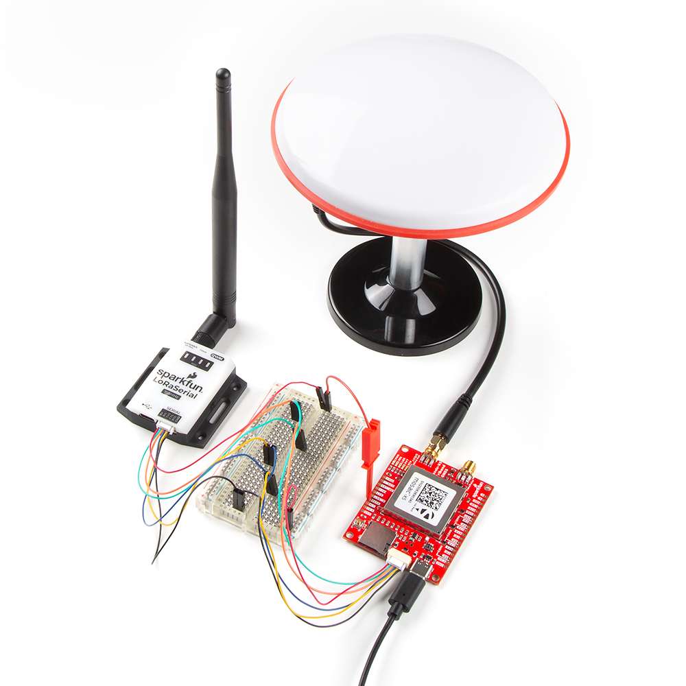
In remote applications, users may need to utilize one of our radio transceivers for RTK correction data. Users may also find our breadboard cable convenient for connecting your module to a development board.
-
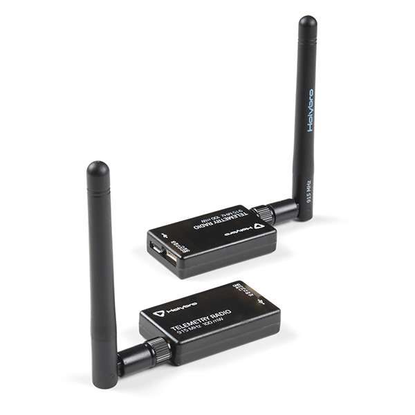
SiK Telemetry Radio V3 - 915MHz, 100mW
WRL-19032 -
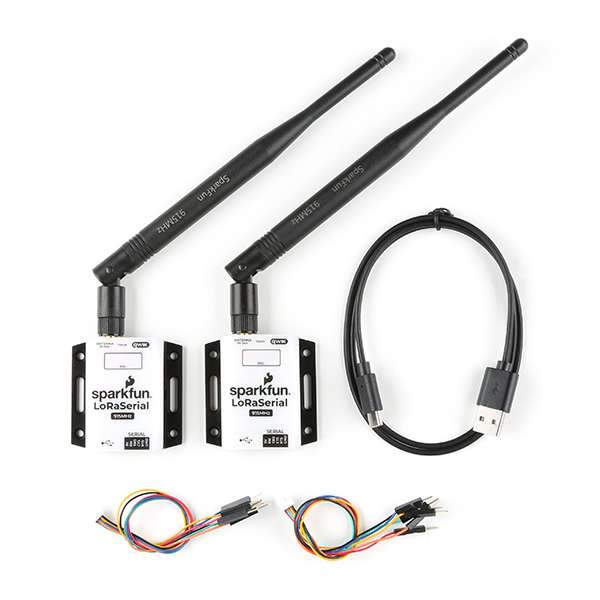
SparkFun LoRaSerial Kit - 915MHz (Enclosed)
WRL-20029 -
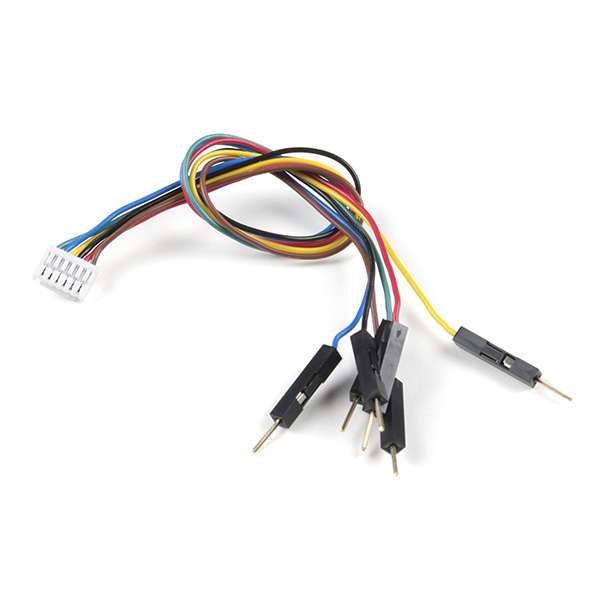
Breadboard to JST-GHR-06V Cable - 6-Pin x 1.25mm Pitch
CAB-18079 -
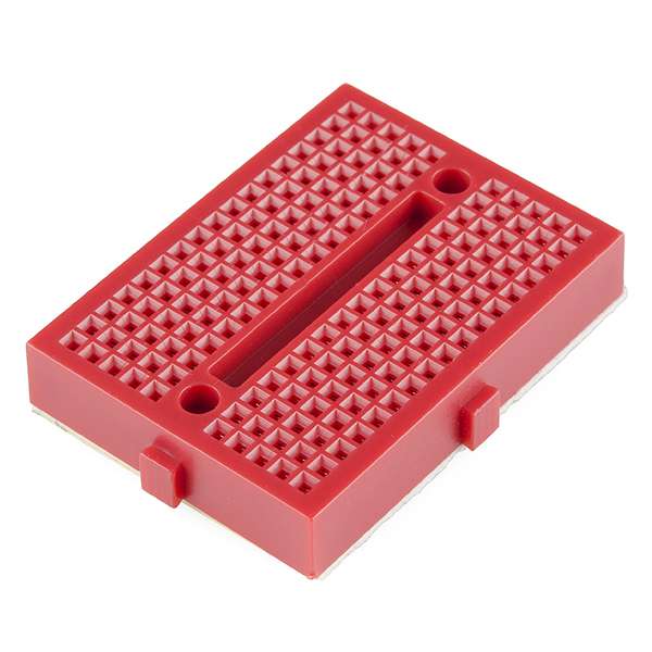
Breadboard - Mini Modular (Red)
PRT-12044
Headers and Wiring
To add headers or hookup wires, users will need soldering equipment and headers/wire.
New to soldering?
Check out our How to Solder: Through-Hole Soldering tutorial for a quick introduction!
-
How to Solder: Through-Hole Soldering
-

Solder Lead Free - 100-gram Spool
TOL-09325 -
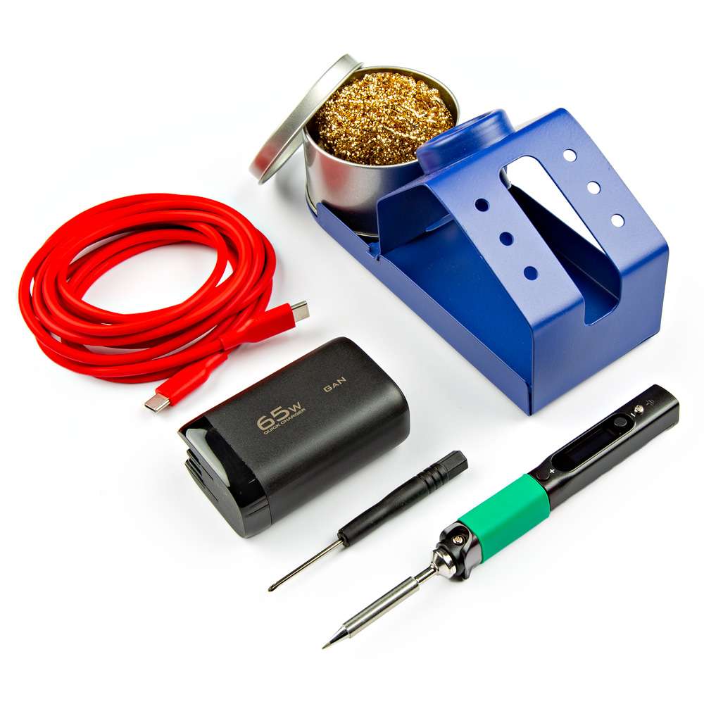
PINECIL Soldering Iron Kit
KIT-24063 -

Chip Quik No-Clean Flux Pen - 10mL
TOL-14579 -
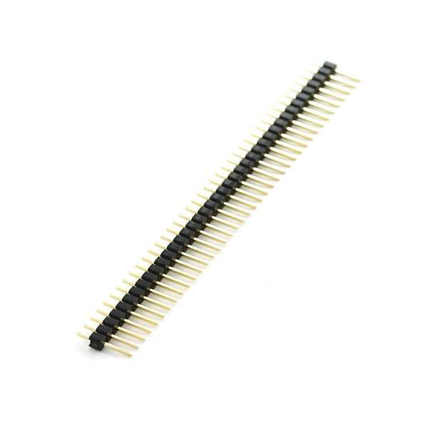
Break Away Headers - Straight
PRT-00116 -
Hook-Up Wire - Assortment (Stranded, 22 AWG)
PRT-11375
Jumper Modification
To modify the jumpers, users will need soldering equipment and/or a hobby knife.
New to jumper pads?
Check out our Jumper Pads and PCB Traces Tutorial for a quick introduction!
-

How to Work with Jumper Pads and PCB Traces
-
Solder Lead Free - 100-gram Spool
TOL-09325 -
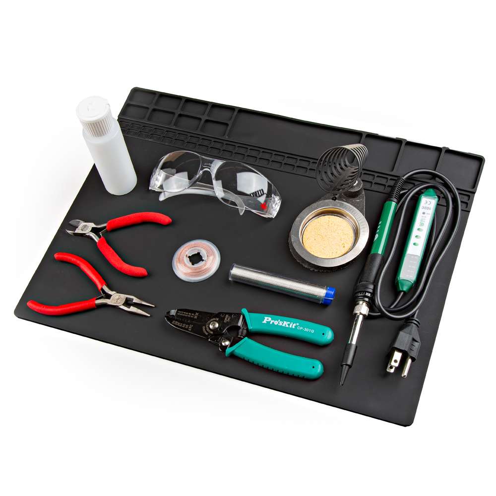
SparkFun Beginner Tool Kit
TOL-22265 -
Chip Quik No-Clean Flux Pen - 10mL
TOL-14579 -
Hobby Knife
TOL-09200
Suggested Reading
As a more sophisticated product, we will skip over the more fundamental tutorials (i.e. Ohm's Law and What is Electricity?). However, below are a few tutorials that may help users familiarize themselves with various aspects of the board.
Tip
Check out the www.gps.gov website to learn more about the U.S.-owned Global Positioning System (GPS) and the Global Navigation Satellite Systems (GNSS) of other countries.
-
GPS Basics
-
What is GPS RTK?
-
RTK mosaic-X5 Hookup Guide
-
Serial Communication
-
Serial Terminal Basics
-
How to Power a Project
-
How to Solder: Through-Hole Soldering
-
How to Work with Jumper Pads and PCB Traces
Related Blog Posts
Additionally, users may be interested in these blog post articles on GNSS technologies:
-

GPS vs GNSS
-

What is Correction Data?
-

Real-Time Kinematics Explained
-
New Video: Unlocking High-Precision RTK Positioning
-

DIY RTK Surveying
Hardware Overview
            TOL-25572</a>

        </div>


!!! warning "Active Antenna"
    Never inject an external DC voltage into the SMA connector for the GPS antenna, as it may damage the mosaic-X5 module. For instance, when using a splitter to distribute the antenna signal to several GNSS receivers, make sure that no more than one output of the splitter passes DC. Use [DC-blocks](https://en.wikipedia.org/wiki/DC_block) otherwise.

    ??? info
        A 3 - 5.5V DC voltage can be applied to the main antenna from the `VANT` pin, obviating the need for an external antenna supply or [bias-tee](https://en.wikipedia.org/wiki/Bias_tee).
Board Dimensions
The board dimensions are illustrated in the drawing below; the listed measurements are in inches.

Board dimensions (PDF) for the Tri-band GNSS RTK breakout board, in inches.
Need more measurements?
For more information about the board's dimensions, users can download the eagle files for the board. These files can be opened in Eagle and additional measurements can be made with the dimensions tool.
Eagle - Free Download!
Eagle is a CAD program for electronics that is free to use for hobbyists and students. However, it does require an account registration to utilize the software.
 Dimensions Tool
This video from Autodesk demonstrates how to utilize the dimensions tool in Eagle, to include additional measurements:

USB-C Connector
The USB connector is provided to power and interface with the mosaic-X5 GNSS receiver. For most users, it will be the primary method for communicating with the mosaic-X5 module.
USB-C connector on the Tri-band GNSS RTK breakout board.
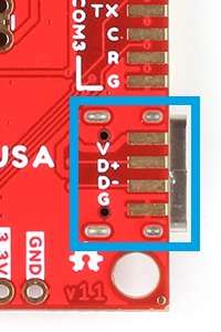
Test Pads
We accidentally mislabeled the test pads underneath the USB-C connector. The silkscreen for the D+ and D- signal lines are reversed.
Power
The Tri-band GNSS RTK breakout board only requires 5V to power all of the board's components. The simplest method to power the board is through the USB-C connector. Alternatively, the board can be converted to utilize 3.3V for low power applications.
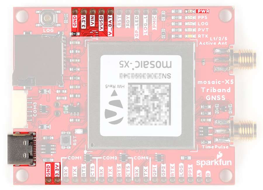
Tri-band GNSS RTK breakout board's power connections.
Below, is a general summary of the power circuitry on the board, broken out as PTH pins:
VUSB- The voltage from the USB-C connector, usually 5V.- Input Voltage Range: 4.4 - 5.5 V
- Power source for the entire board.
- Powers the 3.3V voltage regulator (AP2112) and the active antenna preamplifier for the mosaic-X5 module. (1)
- This pin powers the integrated PHY of the mosaic-X5 module's USB interface.
- Features ESD protection and a thermal fuse.
VIN- Alternate input supply voltage for the board.- Alternative power supply input for the board, excluding the integrated PHY of the USB interface.
- Power source for the entire board.
- Powers the 3.3V voltage regulator (AP2112) and the active antenna preamplifier for the mosaic-X5 module. (2)
- Features a thermal fuse.
3.3V- Provides a regulated 3.3V from AP2112 using the power from theVINorVUSB(5V) inputs.- Input Voltage Range: 3.135 - 3.465 V
- The 3.3V AP2112 LDO regulator can source up to 600mA.
V_BATT- Always-on power supply- Input Voltage Range: 3.135 - 3.465 V
- Tied to
3.3V(see the Jumpers section).- Used to power the module in Standby mode.
GND- The common ground or the 0V reference for the voltage supplies.
-
-
While the AP2112 LDO regulator has an input voltage range of 2.5 - 6V, users should supply:
- A minimum of 3.5V for a 3.3V output from the regulator
- A maximum of 5.5V as not to exceed the electrical limitations of the mosaic-X5 module
-
A 3 - 5.5V DC voltage can be applied to the main antenna from the
VANTpin, obviating the need for an external antenna supply or bias-tee.
-
-
A 3 - 5.5V DC voltage can be applied to the main antenna from the
VANTpin, obviating the need for an external antenna supply or bias-tee.
VIN Input Voltage
While the AP2112 LDO regulator has an input voltage range of 2.5 - 6V, users should supply:
- A minimum of 3.5V for a 3.3V output from the regulator
- A maximum of 5.5V as not to exceed the electrical limitations of the mosaic-X5 module
However, users are able to bypass the electrical limitations of the mosaic-X5 module and power the board with up to 6V. Users just need to modify the ANT_V jumper (see the Jumpers section) to the 3V3 pad.
MEAS Pins
These pins can be used to measure the current being drawn through the USB connector or VUSB/VIN pins (see the Jumpers section).
JST Connector
The V pin of the JST connector is designed for an input voltage to VIN. By default, it does not operate as a voltage output.
Bypass - Reverse Current Protection Diode
Danger - Proceed at Your Own Risk!
By bypassing the reverse current protection diode, users should take precautions to ensure that they do not provide an input voltage to the JST connector, when the board is connected to their computer. Otherwise, it may result in damage to the computer's USB bus.
To enable an output voltage on the JST connector, users will need to bypass the protection diode that prevents reverse current to the USB-C connector. This can be done by jumping the VUSB and VIN pins together.
Once jumpered, when the board is powered through the USB-C connector, the V pin of the JST connector will provide an output voltage from the USB-C connector.
Info
For more details, users can reference the schematic and the datasheets of the individual components on the board.
Power Modes
The mosaic-X5 module operates in three different power states.
- Off - The module is completely turned off
- When transitioning to the Off state from Active, recent data may not be lost and not logged to the external SD card
- Standby - The module is in a low-power consumption mode (1)
- The module power consumption in standby is <5mW
- The
PMIC_ON_REQpin is drivenLOW - The
MODULE_RDYpin is in aLOW - Monitors the state of the
ONOFFpin (Not available)
- Active - The module is operating with all functions active
- On power up, the module restarts in the configuration stored in the boot configuration file
- The
PMIC_ON_REQpin is drivenHIGH - The
MODULE_RDYpin is in aHIGH(2)
- Essentially, the same state as Off; except in the transition to the Standby mode, before the module shuts down:
- All logging tasks are terminated
- The SD card is unmounted
- The
PMIC_ON_REQpin is drivenLOW
- Level becomes
HIGHabout 300ms after powering up, reset, or waking up from standby
Info
By default, the board is hardwired to operate only in the Active and Off modes.
For more information on the power management of the mosaic-X5 module, please refer to sections 3.4, 3.5, 4.1, and 4.13 of the hardware manual.
Enabling Standby Mode
Users can enable Standby mode on the mosaic-X5, by modifying the V_BATT jumper (see the Jumpers section) and providing an external power source for the V_BATT pin (3.3V). However, because the ONOFF pin isn't exposed users will need to power cycle the board to return to the Active state.
Drive Current - PMIC_ON_REQ/MODULE_RDY
The drive current on the PMIC_ON_REQ and MODULE_RDY pins is low. Enough to be read by a digital pin on a microcontroller, but not high enough to drive an LED.
Power Consumption
The power consumption of the mosaic-X5 module depends on the GNSS signals enabled and the positioning mode. The table below, lists the average power consumption for common configurations. The current listed, is based on a supply voltage of 3.3V.
| GNSS Signals | Positioning Mode | Power (mW) | Current (mA) |
|---|---|---|---|
| GPS L1 C/A | Stand-Alone (1Hz) | 550 | 167 |
| GPS L1/L2 | RTK (1Hz) | 670 | 203 |
| GPS/GLONASS L1/L2 | RTK (1Hz) | 695 | 211 |
| GPS/GLONASS L1/L2+GALILEO L1/E5a +BeiDou B1C/B2a | RTK (1Hz) | 850 | 258 |
| GPS/GLONASS L1/L2+GALILEO L1/E5a +BeiDou B1C/B2a | RTK (100 Hz) | 930 | 282 |
| GPS/GLONASS L1/L2 + L-band | PPP (1Hz) | 760 | 230 |
| All signals from all GNSS constellations | Static (1Hz) | 910 | 276 |
| All signals from all GNSS constellations +L-band | Static(1Hz) | 980 | 297 |
| All signals from all GNSS constellations +L-band | Static (100Hz) | 1080 | 327 |
Source: mosaic-X5 Hardware Manual
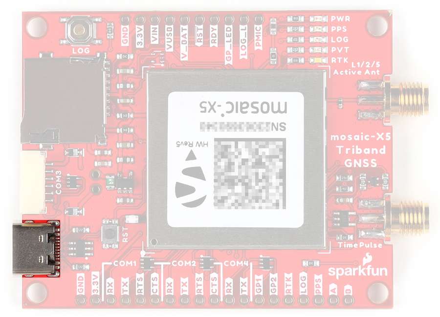
mosaic-X5
The centerpiece of the Tri-band GNSS RTK breakout board, is the mosaic-X5 module from Septentrio. Their mosaic modules are low-power, multi-band, multi-constellation GNSS receivers capable of delivering centimeter-level precision at high update rates. The modules also feature Septentrio's unique AIM+ technology for interference mitigation and anti-spoofing, which ensures their best-in-class reliability and scalable position accuracy.

The mosaic-X5 module on the Tri-band GNSS RTK breakout board.
Features:
- Operating Voltage: 3.135 - 3.465V
- Operating Temperature: -40 - 85°C
- GNSS Support
- GPS: L1C/A, L1PY, L2C, L2P, L5
- GLONASS: L1CA, L2CA, L2P, L3 CDMA
- Beidou: B1I, B1C, B2a, B2b, B2I, B3
- Galileo: E1, E5a, E5b, E5 AltBoc, E6
- QZSS: L1C/A, L1 C/B, L2C, L5
- Navic: L5
- SBAS: Egnos, WA
- Antenna Specifications
- Preamplification Range: 15-50dB
- Bias Voltage: 3.0 - 5.5V
- 448 Hardware Channels
- Update Rate: 100Hz
- Latency: < 10ms
- Time to Fix
- Cold Start: < 45s
- Warm: < 20s
- Reacquisition: 1s
- Timing Precision: 5ns
-
Position Accuracy
Correction Horizontal Vertical RTK 0.6cm (±0.5ppm)
~0.25"1cm (±1ppm)
~.4"DGNSS 40cm
~1.3'70cm
~2.3'SBAS 60cm
~2'80cm
~2.6'Standalone 1.2m
~4'1.9m
~6.2'
Info
The mosaic-X5 has three power modes: Active, Standby, and Off (see the Power Modes section).
Frequency Bands
The mosaic modules are multi-band, multi-constellation GNSS receivers. Below, are charts illustrating the frequency bands utilized by all the global navigation satellite systems and the ones supported by the mosaic-X5 module.
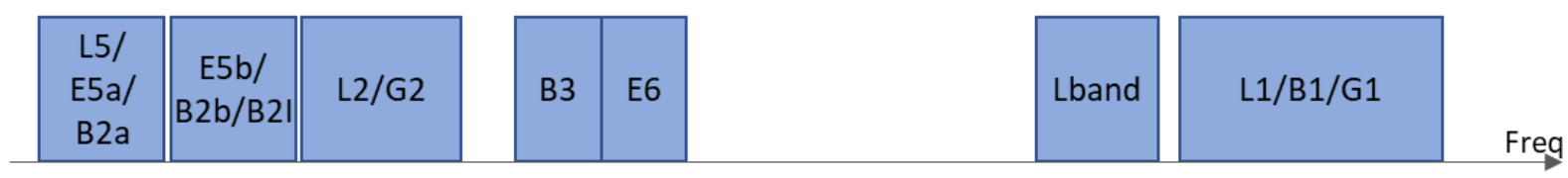
The frequency bands supported by the mosaic-X5 GNSS receiver.
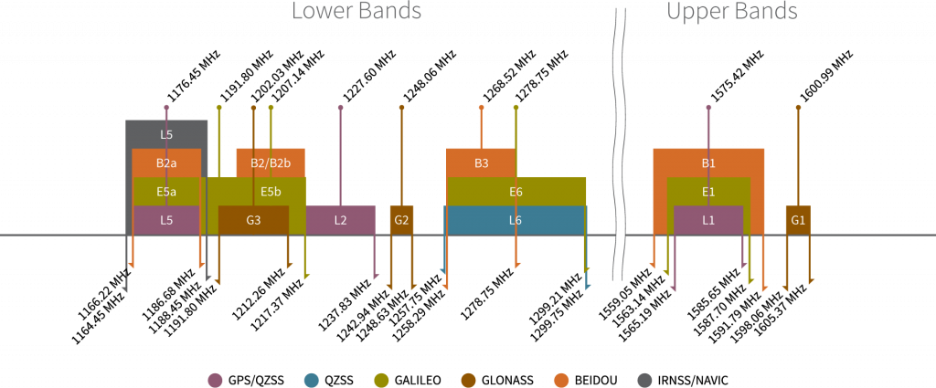
Frequency bands of the global navigation satellite systems. (Source: Tallysman)
Info
For a comparison of the frequency bands supported by the mosaic modules, refer to section 3.1 of the hardware manual.
What are Frequency Bands?
A frequency band is a section of the electromagnetic spectrum, usually denoted by the range of its upper and lower limits. In the radio spectrum, these frequency bands are usually regulated by region, often through a government entity. This regulation prevents the interference of RF communication; and often includes major penalties for any interference with critical infrastructure systems and emergency services.

However, if the various GNSS constellations share similar frequency bands, then how do they avoid interfering with one another? Without going too far into detail, the image above illustrates the frequency bands of each system with a few characteristics specific to their signals. Wit these characteristics in mind, along with other factors, the chart can help users to visualize how multiple GNSS constellations might co-exist with each other.
For more information, users may find these articles of interest:
Position Accuracy
The accuracy of the position reported from the mosaic-X5 module, can be improved based upon the correction method being employed. Currently, RTK corrections provide the highest level of accuracy; however, users should be aware of certain limitations of the system:
- RTK technique requires real-time correction data from a reference station or network of base stations.
- RTK corrections are signal specific (i.e. an RTK network might provide corrections on only
E5band notE5a).
- RTK corrections are signal specific (i.e. an RTK network might provide corrections on only
- The range of the base stations will vary based upon the RTK method being employed.
- The reliability of RTK corrections are inherently reduced in multipath environments. However, with Septentrio's multipath mitigation technology (APME+) on the mosaic-X5, these errors are significantly reduced when compared to multipath mitigation techniques that modify the correlators in the tracking channels.
RTK Corrections
To understand how RTK works, users will need a more fundamental understanding of the signal error sources.
-
Real-Time Kinematics Explained
-
What is Correction Data?
-

GNSS Corrections Demystified
Tip
For the best performance, we highly recommend that users configure the module to utilize/provide RTK corrections with a compatible L1/L2/L5 (tri-band) GNSS antenna and utilize a low-loss cable.
Peripherals and I/O Pins
The mosaic-X5 features several peripherals and I/O pins. Some of these are broken out as pins on the Tri-band GNSS RTK breakout board; whereas, others are broken out to their specific interface (i.e. µSD Carsd slot, USB connector, etc.). Additionally, some of their connections are tied to other components on the board.
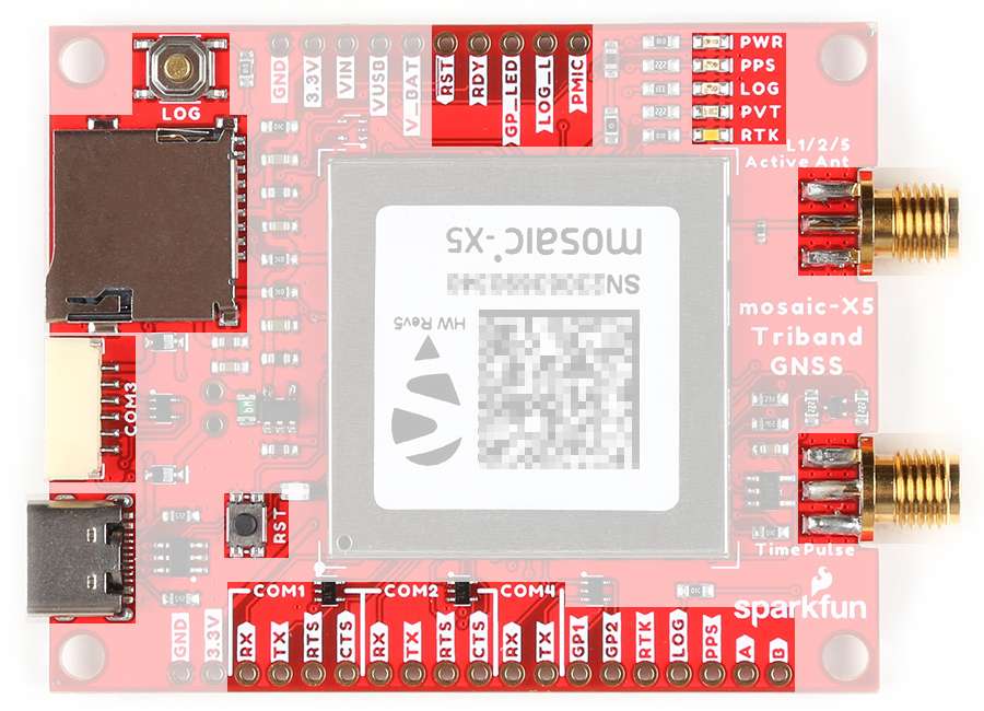
The peripherals and I/O pins on the Tri-band GNSS RTK breakout board.
Interfaces:
- 4x UART (LVTTL, up to 4 Mbps)
Ethernet (RMII/MDIO), 10/100 Mbps(1)- USB device (2.0, HS)
- SDIO (mass storage)
- 2x GPIO user programmable
- 2x Event markers
- 1x Configurable PPS out
- Not available on the Tri-band GNSS RTK breakout board.
For most users, this will be the primary interface for the mosaic-X5 module.
- When a module is initially connected to a computer, the board will initialize as a USB mass storage device.
- For Windows PCs, the USB driver (1) can be installed from the mass storage device or the RxTools software suite.
- When the SD card is mounted, this drive will contain the contents of the SD card that is inserted on the board.
- Once the USB driver is installed:
- Two virtual
COMports are emulated, which can be used as standardCOMports to access the receiver. - This interface will support Ethernet-over-USB.
- By default, the receiver is not allowed to access the Internet over USB.
- The IP address allocated to the Ethernet-over-USB interface is
192.168.3.1.- The IP address cannot be changed; therefore, only single receiver should be connected to your computer at a time.
- Two virtual
- On Linux, the standard Linux CDC-ACM driver is suitable.
The mosaic-X5 has four UARTs that are organized into separate COM ports. The operation for each of these ports can be configured separately.
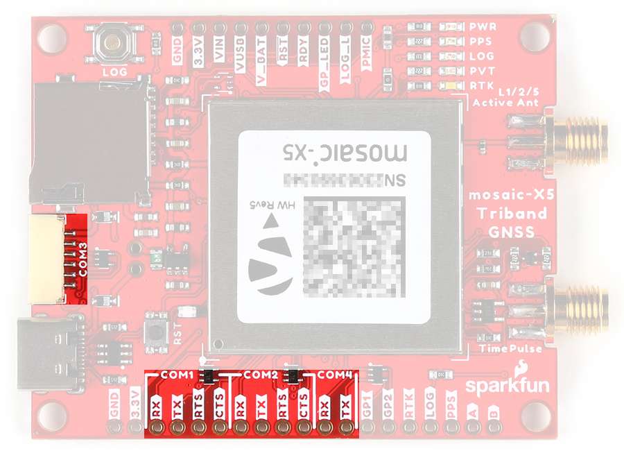
COM ports on the Tri-band GNSS RTK breakout board.
COMports 1-3 feature flow control pins, which are disabled by default.COM3is available through the JST connector(1), but the pins can also be accessed from the pads on the bottom of the board.- These ports also support a point-to-point protocol server, by which it can accept TCP/IP connections over a serial link.
-
Breadboard to JST-GHR-06V Cable - 6-Pin x 1.25mm Pitch
CAB-18079
Info
By default, the COM ports will be configured with the following settings:
- Baudrate: 115200bps
- Data Bits: 8
- Parity: No
- Stop Bits: 1
- Flow Control: None
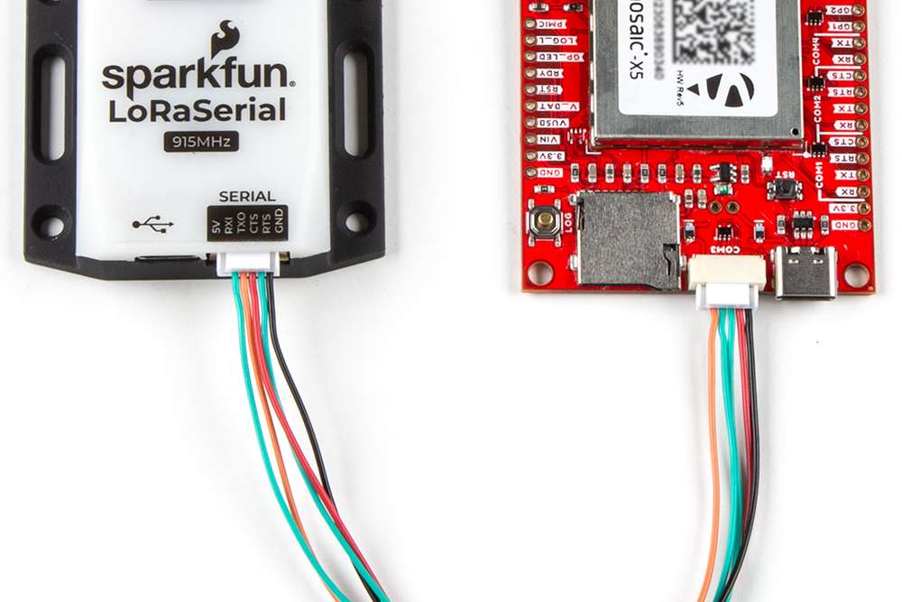
Pin Connections
When connecting to the board's UART pins, the pins should be connected based upon the flow of their data. For example, when utilizing the Telemetry Radio or the LoRaSerial Kit:
Users will need to connect a compatible GPS antenna to the L1/2/5 ActiveAnt SMA connector. The type of antenna used with the mosaic-X5 module affects the overall accuracy of the positions calculated by the GNSS receiver.
- An active antenna often features a LNA. This allows the module to boost the signal received by the GNSS module without degrading the SNR.
- The more bands an antenna supports, the greater the performance.
- Faster acquisition time.
- Access and support for the
L5GPS band can potentially mitigate multi-path errors. - Supporting more frequency bands, allows a GNSS receiver to be less susceptible to jamming and spoofing.
Tip
For the best performance, we recommend users choose a compatible L1/L2/L5 (tri-band) GNSS antenna and utilize a low-loss cable.
There are some key parameters related to an antenna that can make or break the signal reception from the satellites. These include the operation frequency, gain, polarization, efficiency and overall loss.

Info
The VANT pin provides external power for an active antenna. By default, this supply voltage is configured at 5V (see the Jumpers section).
Danger
Never inject an external DC voltage into the SMA connector for the GPS antenna, as it may damage the mosaic-X5 module. For instance, when using a splitter to distribute the antenna signal to several GNSS receivers, make sure that no more than one output of the splitter passes DC. Use DC-blocks otherwise.
From the module, the PPS output signal's logic-level is 1.8V. However, for the convenience of users, we have added a buffer and bumped up the signal's logic-level to 3.3V on the Tri-band GNSS RTK breakout. This 3.3V signal output can be access through the SMA connector and the PPS pin. The signal is also connected to the PPS LED, to be used as a visual indicator.

PPS signal's outputs on the Tri-band GNSS RTK breakout board.
Jumpers
See the Jumpers section for more details.
- There is a jumper attached to the
PPSpin. When cut, it disconnects the pin from the PPS signal. - There is a jumper attaches to the
PPSLED. For low power applications, the jumper can be cut to disable thePPSLED.
Use Case
- Users could use this signal in conjunction with the event pins to synchronize two mosaic-X5 modules with each other.
- Users could use this signal to create their own Stratum 0 source for the NTP on a primary time server.
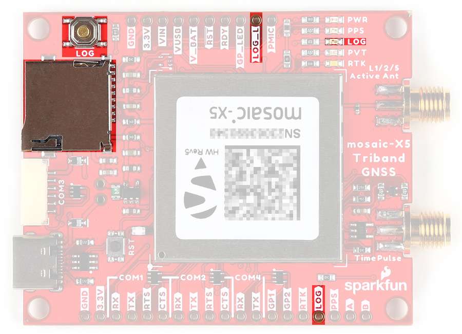
The data logging functionality of the board can be configured through the software/web interfaces or through the use of the LOG button or LOG pin (1). Data logging activity will be indicated by the LOG status LED (2).
- The LOG button and
LOGpin are connected to the same active-high, input of the mosaic-X5. Pressing the button or pulling the pin low will toggle the data logging feature. Whereas, holding them for more than 5 seconds will mount/unmount the SD card (see the Log Button section). - See the SD Card Slot section
- Button
- LOG - Connected to the
LOGpin
- LOG - Connected to the
- Pins
LOG- Connected to the LOG buttonLOG_L- Connected to theLOGLED- µSD Card Slot - Connected to the SDIO pins
- LED
LOG- Connected to theLOG_Lpin
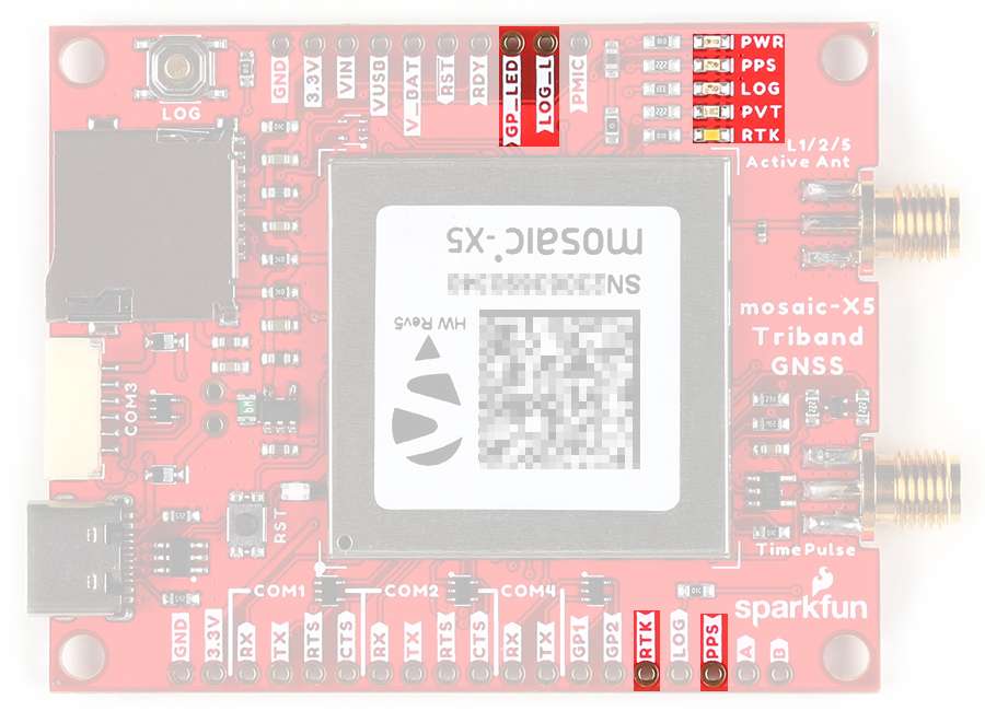
The mosaic-X5 module features two general purpose, output LED pins. These pins have a maximum output current of 10 mA and output impedance of 20Ω. In addition, to these pins, there are several status LEDs on the board (see the Status LEDs section).
- The general purpose LED pins are connected to the
RTKandPVTLEDs; and respectively, theRTKandGP_LEDpins. - The PPS output signal is connected to the
PPSpin,PPSLED, andTimePulseSMA connector. - The
LOG_Lpin is connected to theLOGLED.
Info
See the Status LEDs section.
The mosaic-X5 module features two general purpose, output pins. These pins can drive a maximum current of 10mA.
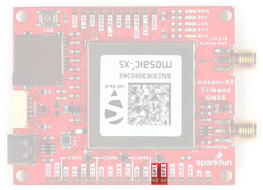
GPx pins on the Tri-band GNSS RTK breakout board.
The mosaic-X5 module features two general purpose, event input pins. These pins can be used to time tag external events with a time resolution of 20ns.

Tip
For example, these pins can be used in conjunction with the PPS output signal for time syncing.
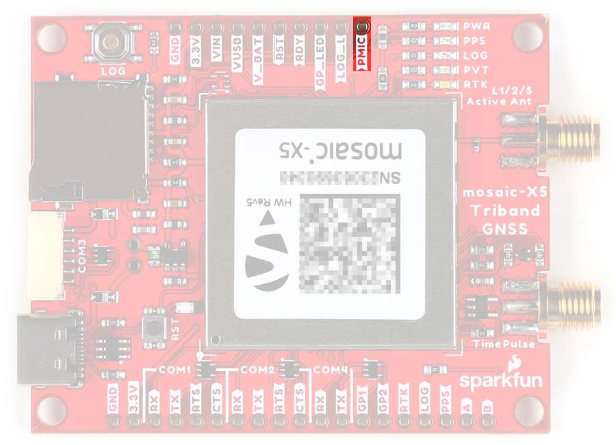
The state of PMIC pin indicates when the subsystems are energized and ready (see the Power Modes section). It can be used as a power switch to drive external power to the antenna (VANT) (see the Jumpers section).
The RDY pin indicates the operational mode of the mosaic-X5 module (see the Power Modes section). The level is high when module is operating, and low when in standby or reset.

SMA Connectors
There are two SMA connectors on the Tri-band GNSS RTK breakout board.
The TimePulse connector provides a PPS output signal (see the PPS Output section).
JST Connector
The Tri-band GNSS RTK breakout features a 6-pin JST GH connector, which is polarized and locking. Users can access the COM3 port of the mosaic-X5 module, through the JST connector with our breadboard cable(1).
-
Breadboard to JST-GHR-06V Cable - 6-Pin x 1.25mm Pitch
CAB-18079
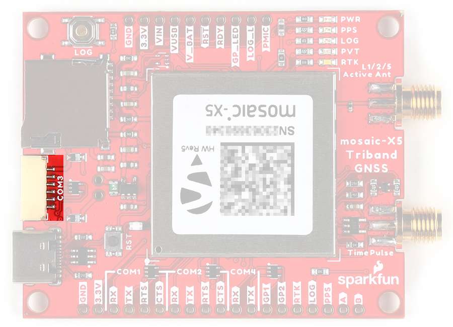
The JST connector on the Tri-band GNSS RTK breakout board.
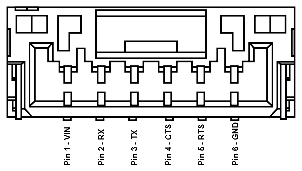
The pin connections of the JST connector on the Tri-band GNSS RTK breakout board.
Pin Connections
When connecting to the board's UART pins, the pins should be connected based upon the flow of their data. For example, when utilizing the Telemetry Radio or the LoRaSerial Kit:
V Pin
By default, the power pin (i.e. V or Pin 1) of the JST connector is connected to VIN and configured as a power input. The board can be modified to configure that pin as a power output; however, the modification would bypass some of the safety features of the board (see the Power section).
SD Card Slot
The µSD card slot allows users easily log and store data on the board.

The µSD card slot on the Tri-band GNSS RTK breakout board.
Initial Configuration
Before data logging can occur, it is necessary to create a logging stream from the Logging tab of the web interface or using the RxTools software suite. Streams can contain NMEA or SBF (Septentrio Binary Format) data; SBF can contain RTCM and/or RINEX. (see the Data Logging section)
SD Card Specifications
The mosaic-X5 module is only compatible with SD cards of up to 32GB, formatted with a FAT32 file system.
Standby Mode
When Standby mode is initialized, the module terminates all running processes and unmounts the external SD card to avoid any log file corruption (see the Power Modes section).
LOG Button
Data logging can be controlled with the LOG button (see the Log Button section).
- Pressing the LOG button (< 5s) toggles data logging to the SD card on and off.
- Holding the LOG button for more than 5 seconds (> 5s) and then releasing it, will force the board to:
- Unmount the SD card if it was mounted
- Mount the SD card if it was unmounted
LOG Status LED
The SD card mount status is indicated on the LOG LED andLOG_L pin (see the Status LEDs section).
| LED | Pin | Status |
|---|---|---|
| Off | Low | SD card not present or unmounted |
| On | High | SD card present and mounted |
| Blinking | Pulses | Data logging activity |
Status LEDs
There are five status LEDs on the TMC6300 motor driver:
PWR- Power (Red)- Turns on once power is supplied through the USB-C connector or
VINconnections
- Turns on once power is supplied through the USB-C connector or
PPS- Pulse-Per-Second (Yellow)- Indicates when there is a pulse-per-second signal (see the PPS Output section)
LOG- Data Logging (Green)- Indicates data logging activity (see the SD Card Slot section)
- Off - SD card not present or unmounted
- On - SD card present and mounted
- Blinking - Data logging activity
- Indicates data logging activity (see the SD Card Slot section)
PVT- Position/Velocity/Time Solution (Blue)- Turns on when a PVT solution is available
RTK- RTK Mode (White)- Controlled through
GPIO 02
- Controlled through

The status indicator LEDs on the Tri-band GNSS RTK breakout board.
Buttons
There are two buttons on Tri-band GNSS RTK breakout board: RST and LOG buttons.

Buttons on the Tri-band GNSS RTK breakout board.
Reset Button
The RST (reset) button allows users to reset the mosaic-X5 module without unplugging the board.
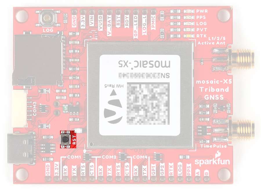
RST button on the Tri-band GNSS RTK breakout board.
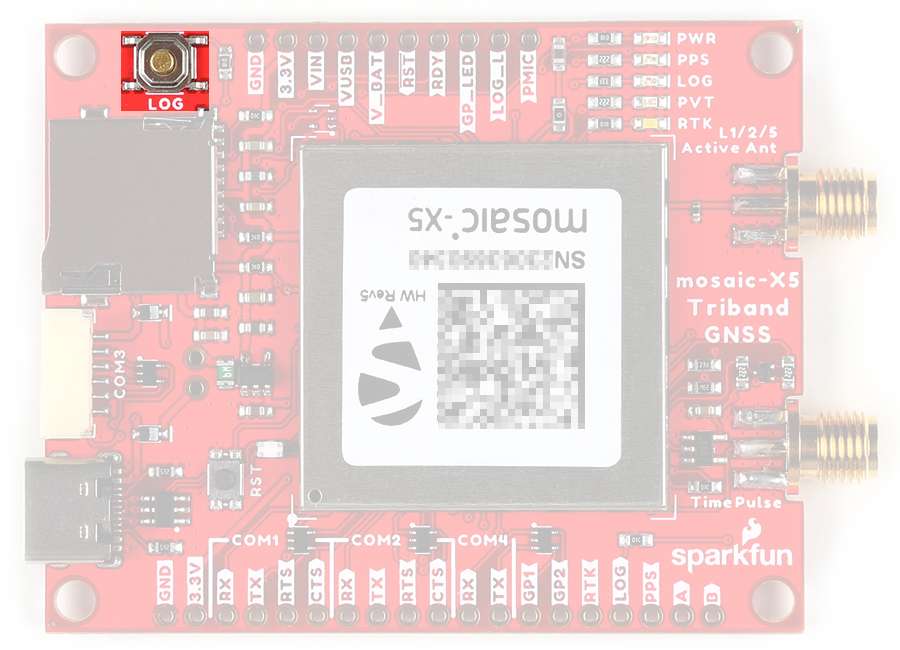
Log Button
The LOG button allows users easily control the data logging feature and the µSD card, without having to configure the module.
- Pressing the LOG button (< 5s) toggles data logging to the SD card on and off.
- Holding the LOG button for more than 5 seconds (> 5s) and then releasing it, will force the board to:
- Unmount the SD card if it was mounted
- Mount the SD card if it was unmounted
SD Card Status
The SD card mount status is indicated on the LOG LED andLOG_L pin (see the Status LEDs section).
| LED | Pin | Status |
|---|---|---|
| Off | Low | SD card not present or unmounted |
| On | High | SD card present and mounted |
| Blinking | Pulses | Data logging activity |
The LOG button on the Tri-band GNSS RTK breakout board.
Jumpers
Never modified a jumper before?
Check out our Jumper Pads and PCB Traces tutorial for a quick introduction!
-
How to Work with Jumper Pads and PCB Traces
There are nine jumpers on the back of the board that can be used to easily modify the hardware connections on the board.
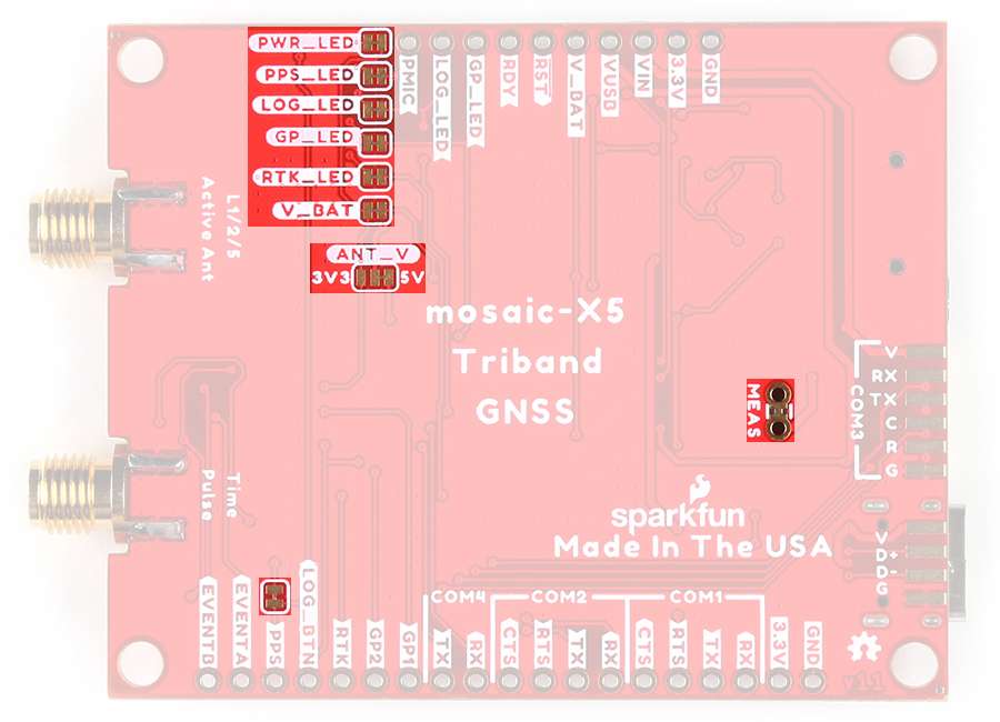
The jumpers on the back of the Tri-band GNSS RTK breakout board.
MEAS-
This jumper can be cut and used to measure the current consumption of the board from the
VUSBand/orVINpower supply inputs. V_BATT-
This jumper can be cut to disconnect the
VBATTpin from the 3.3V output of the AP2112 LDO regulator.Info
The
VBATTpin is the power input for the mosaic-X5 module, when it is in Standby mode. Therefore, it also determines the power state of the mosaic-X5 module, when power is disconnected from theVUSBandVINinputs.- By default, the jumper connected and the
VBATTpin is powered at 3.3V. When the primary power is disconnected, the mosaic-X5 module will enter Standby mode. - If cut, the
VBATTpin will be disconnected from the 3.3V output of the AP2112 LDO regulator. When the primary power is disconnected theVUSBandVINinputs, the mosaic-X5 module will shut off.
- By default, the jumper connected and the
ANT_V-
This jumper can be modified to control the output voltage of the active antenna connection.
Info
By default, the middle pad is connected to the
5Vpad, which draws power from theVUSBand/orVINinputs.Users can modify the jumper, to configure the output voltage of the active antenna connection to 3.3V, by cutting the jumper and connecting the middle pad to the
3V3pad.
There are five jumpers that control power to the status LEDs on the board.
Info
By default, all the jumpers are connected, to power the status LEDs. For low power applications, users can cut the jumpers to disconnect power from each of the LEDs.
PWR_LED- This jumper can be cut to remove power from the red, power LED.PPS_LED- This jumper can be cut to remove power from the yellow LED, which is connected to the PPS signal.LOG_LED- This jumper can be cut to remove power from the green LED, which indicates if data is being logged to the SD card.GP_LED- This jumper can be cut to remove power from the blue LED that is connected to the general purpose pins.RTK_LED- This jumper can be cut to remove power from the white LED, indicating RTK corrections.
Hardware Assembly
            TOL-25572</a>

        </div>


!!! warning "Active Antenna"
    Never inject an external DC voltage into the SMA connector for the GPS antenna, as it may damage the mosaic-X5 module. For instance, when using a splitter to distribute the antenna signal to several GNSS receivers, make sure that no more than one output of the splitter passes DC. Use [DC-blocks](https://en.wikipedia.org/wiki/DC_block) otherwise.

    ??? info
        A 3 - 5.5V DC voltage can be applied to the main antenna from the `VANT` pin, obviating the need for an external antenna supply or [bias-tee](https://en.wikipedia.org/wiki/Bias_tee).
USB Programming
The USB connection is utilized for programming and serial communication. Users only need to plug their Tri-band GNSS RTK breakout board into a computer using a USB-C cable.
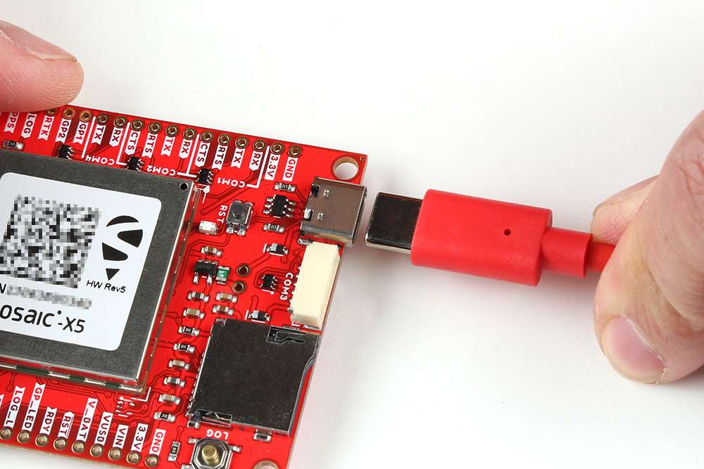
The Tri-band GNSS RTK breakout board with USB-C cable being attached.
GPS Antenna
In order to receive GNSS signals, users will need to connect a compatible antenna. For the best performance, we recommend users choose an active, L1/L2/L5 (tri-band) GNSS antenna and utilize a low-loss cable.

Attaching a GPS antenna to the SMA connector on the Tri-band GNSS RTK breakout board.
SD Card
An µSD card slot is available for users to log and store data, locally on the board. Users, will need to insert a compatible SD card and configure the mosaic-X5 module for data logging.

Inserting an SD card into the Tri-band GNSS RTK breakout board.
Tip
There are multiple ways to configure and enable data logging to an SD card. However, the simplest method is with the LOG button.
- Pressing the LOG button (< 5s) toggles data logging to the SD card on and off.
- Holding the LOG button for more than 5 seconds (> 5s) and then releasing it, will force the board to:
- Unmount the SD card if it was mounted
- Mount the SD card if it was unmounted
For more information, please reference the SD Card Slot section.
JST Connector
The JST connector on the Tri-band GNSS RTK board, breaks out the COM3 UART port of the mosaic-X5 module.
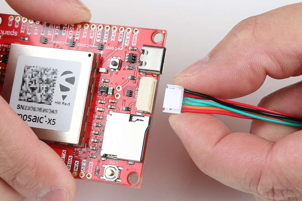
Connecting a cable to the JST connector of the Tri-band GNSS RTK breakout board.
Connecting a Radio
Radio Transceivers
In most circumstances, users will utilize the JST connector to interface with one of our radio transceivers for RTK correction data:
-
SiK Telemetry Radio V3 - 915MHz, 100mW
WRL-19032 -
SparkFun LoRaSerial Kit - 915MHz (Enclosed)
WRL-20029
Pin Connections
When connecting the Tri-band GNSS RTK breakout board to one of our radio transceivers, users need to be aware of the pin connections between the products; as their pin layout is mirrored on each connector. Although the labels on each device may vary, their pins will operate exactly the same; with the exception of the input voltage ranges.
| Pin Number |
1 (Left Side) |
2 | 3 | 4 | 5 |
6 (Right) |
|---|---|---|---|---|---|---|
| Label |
V - Triband 5V - Radios |
RX - Triband/SiK RXI - LoRaSerial |
TX - Triband/SiK TXO - LoRaSerial |
C - Triband CTS - Radios |
R - Triband RTS - Radios |
G - Triband GND - Radios |
| Function |
Voltage Input - Triband: 3.5 to 5.5V - SiK: 5V - LoRaSerial: 3.3 to 5V |
UART - Receive | UART - Transmit |
Flow Control Clear-to-Send |
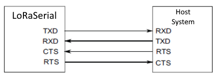
Flow Control Ready-to-Send |
Ground |
Pin Connections
-
When connecting the Tri-band GNSS RTK breakout board to either of the radios, the pin connections should follow the table below. If the flow control is not enabled, the only the
RX,TX, andGNDpins are utilized.Triband RX TX RTS CTS GND Radio TX RX CTS RTS GND -
As documented in the LoRaSerial product manual, the pin connections between a host system (i.e. Tri-band GNSS RTK breakout board) and the LoRaSerial Kit radio is outlined in the image below.
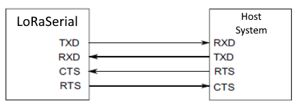
The COMports on the Tri-band GNSS RTK breakout board.
Wiring Connections
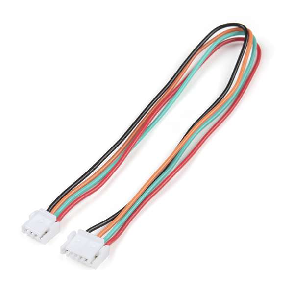
Users have several options for wiring up these two products. Without creating a custom cable assembly, we recommend utilizing our breadboard cable along with any breadboard or F/F jumper wires.
-
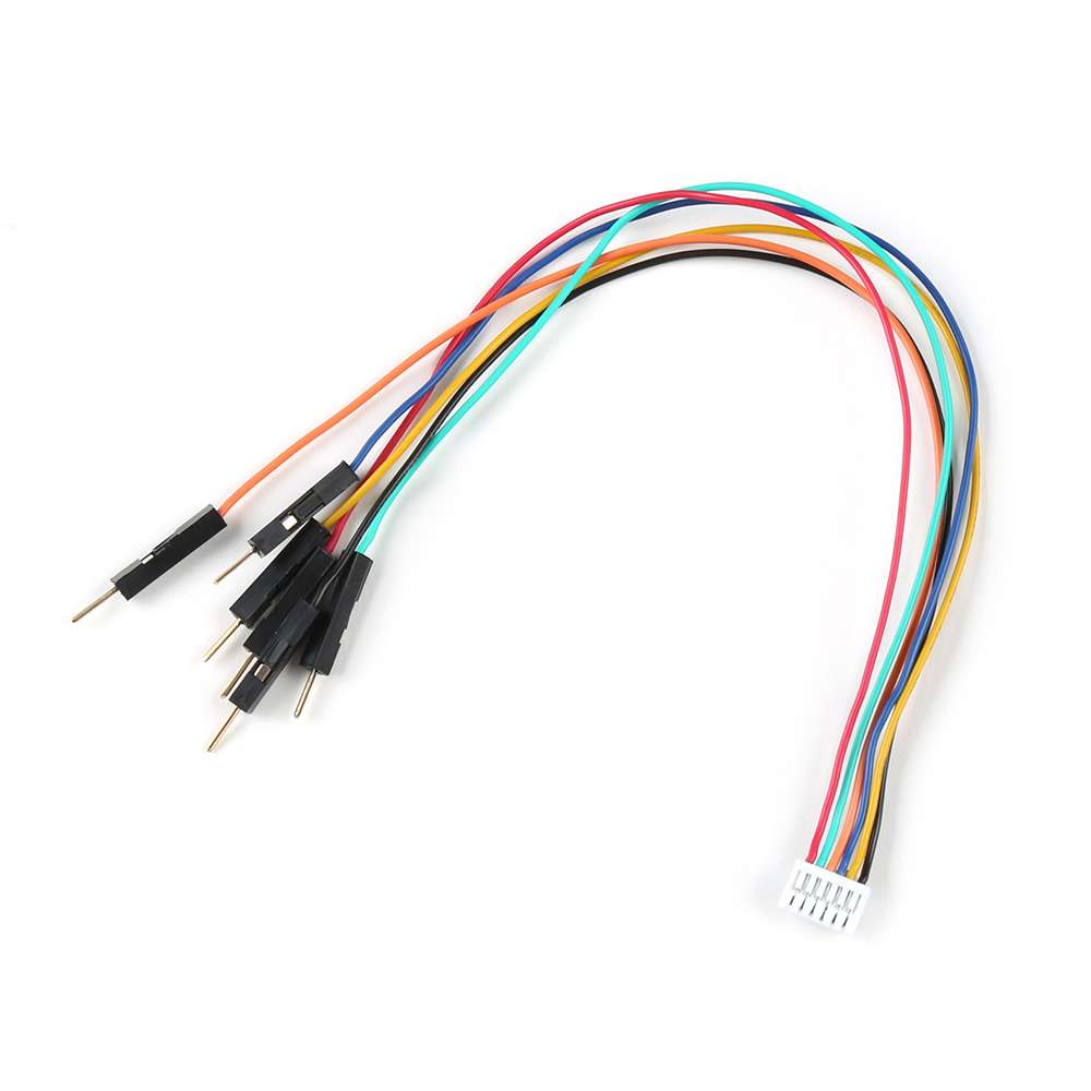
Breadboard to JST-GHR-06V Cable - 6-Pin x 1.25mm Pitch (For LoRaSerial)
CAB-23353 -
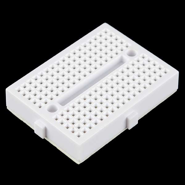
Breadboard - Mini Modular (White)
PRT-12043
Following the pin connections, outlined in the table above, users can wire up the two devices. In the figures below, a reference diagram for the pin connections of JST connector are provided along with an example setup, using a breadboard. However, users are free to utilize the products/methods that suit their project requirements.
-
Below if a diagram of the pin connections for the 6-pin JST GH connector on the devices that users can reference without having to pull up the datasheet or product manuals.
The pin connections of the JST connector on the Tri-band GNSS RTK breakout board. Warning
Please remember that the power pin, is a voltage input and should not be utilized to transfer power between the devices. Users should power their devices separately through the USB connectors on the devices.
-
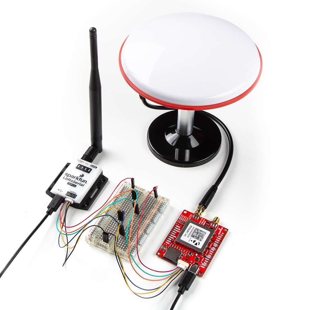
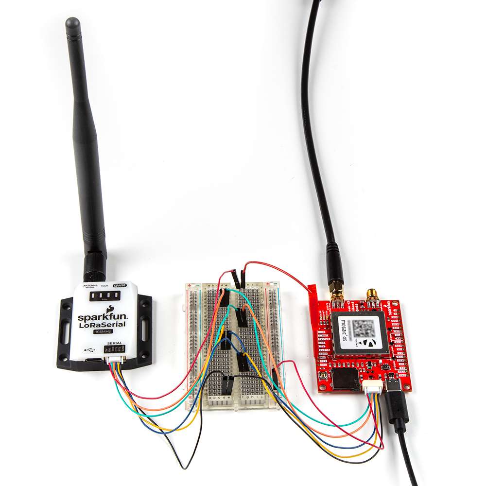
Below, is an example illustrating the Tri-band GNSS RTK breakout board being connected to the LoRaSerial Kit - 915MHz utilizing the breadboard cable and breadboard.
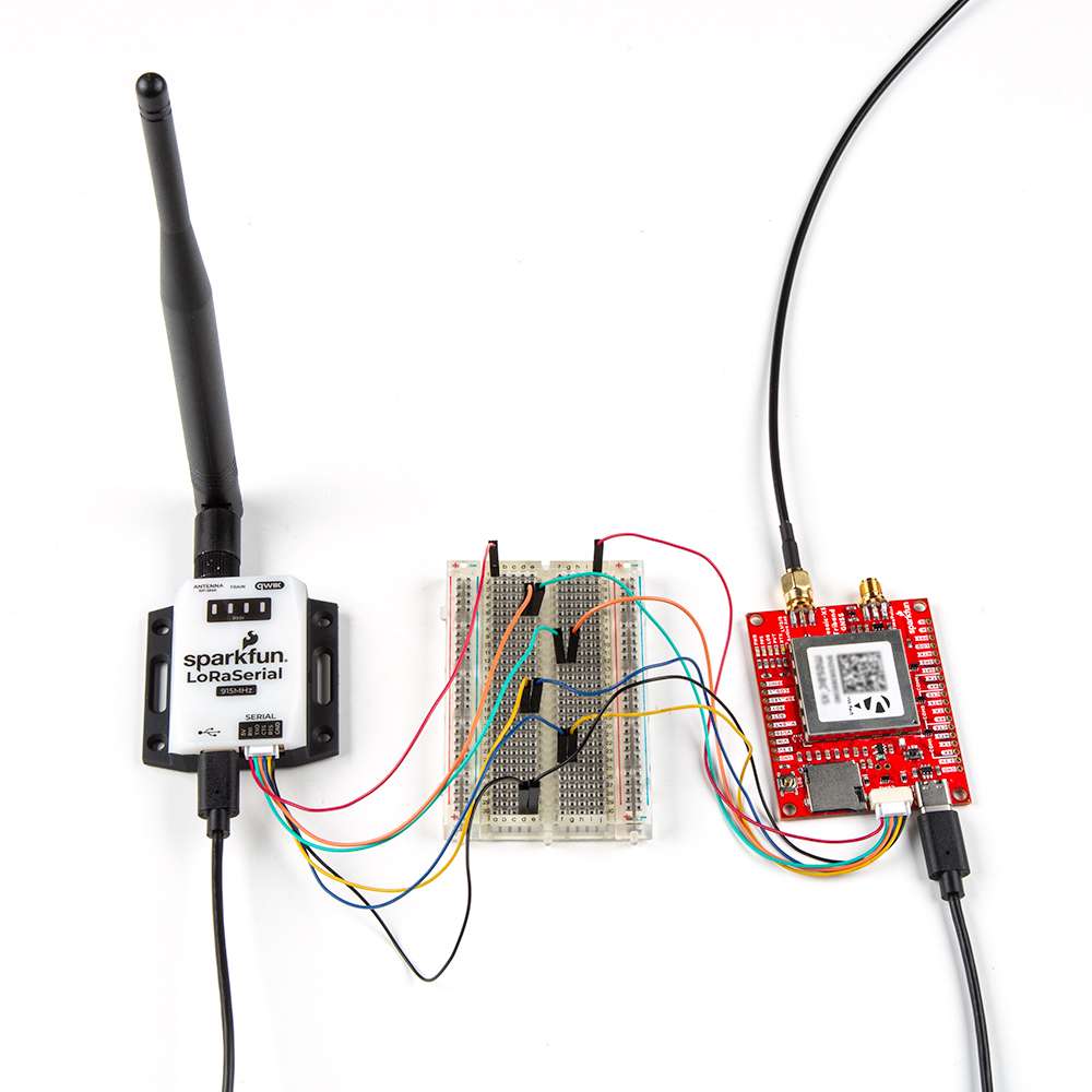
The Tri-band GNSS RTK breakout being connected to the LoRaSerial Kit - 915MHz. In this example, the devices are being powered separately through their USB ports. This is because the devices power pins are configured as voltage inputs. (Click the image to enlarge, users will notice that the power pins are not connected together, unlike the other pins.)
When complete, the setup should appear similar to the figure below.
Pairing Radios
By default, the radios in the LoRaSerial Kit - 915MHz are pre-configured for point-to-point communication and a paired with each other. For instructions on other configurations, please reference the product manual for the LoRaSerial Kit.
Custom Crossover Cable
Users could potentially create their own custom cable from our existing cable assembly. However, this would require delicate dexterity skills as the plastic pins of the harness's connector easily break. Two cable assemblies are required to create a single custom wiring harness (i.e. crossover cable).
-
JST-GHR-04V to JST-GHR-06V Cable - 1.25mm pitch
CAB-17239
Following the pin connections, outlined in the table above, users would rewire the cable assembly. Make sure not to exclude the power pin connection; on both devices, that pin is for an input voltage on the JST connector.

Enabling a Voltage Output
Disclaimer
Due to the inherent risks of the modifications below, technical assistance will not be provided nor will refunds or returns be authorized for products with the following modifications.
By proceeding with the instructions below, users acknowledge that they are purposefully circumventing the reverse current protection diode on the board. By doing so, this can potentially expose their computer and any other devices to be permanently damaged. Proceed at your own risk!
Enable Voltage Output
While not recommended, because it bypasses the reverse current protection diode, users can enable a voltage output on the JST connector of the Tri-band GNSS RTK breakout board. Below are two different modifications that users could potentially utilize.
Jumper Pin Modification
The jumper pin modification requires a header to be soldered to the VIN and VUSB pins of the Tri-band GNSS RTK breakout board. Then a 2-pin jumper is utilized to bypass the protection diodes between the two pins. The example in the image below, utilizes a simple straight header. When a jumper is placed on the VIN and VUSB pins, any power that is provided through the USB-C connector of the Tri-band GNSS RTK breakout, will now be connected to the the power pin of the JST connector.

-
Break Away Headers - Straight
PRT-00116
-
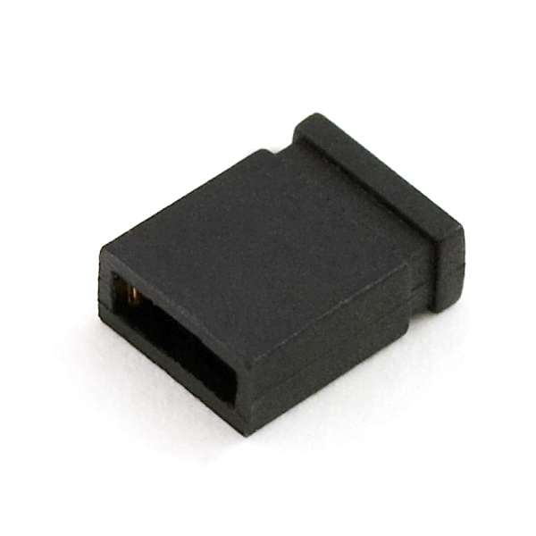
Jumper - 2 Pin
PRT-09044
IC-Hook Modification
The IC-hook modification utilizes an IC-hook w/ pigtail to breakout the VUSB pin of the Tri-band GNSS RTK breakout board on a jumper wire.
-
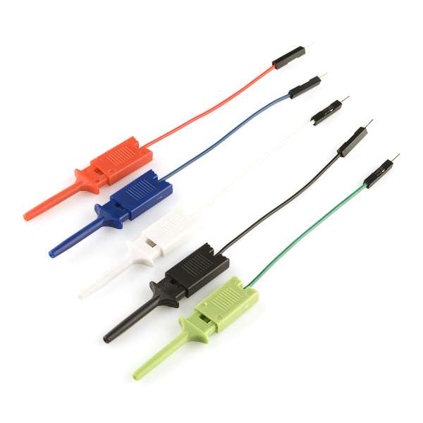
IC Hook with Pigtail
CAB-09741
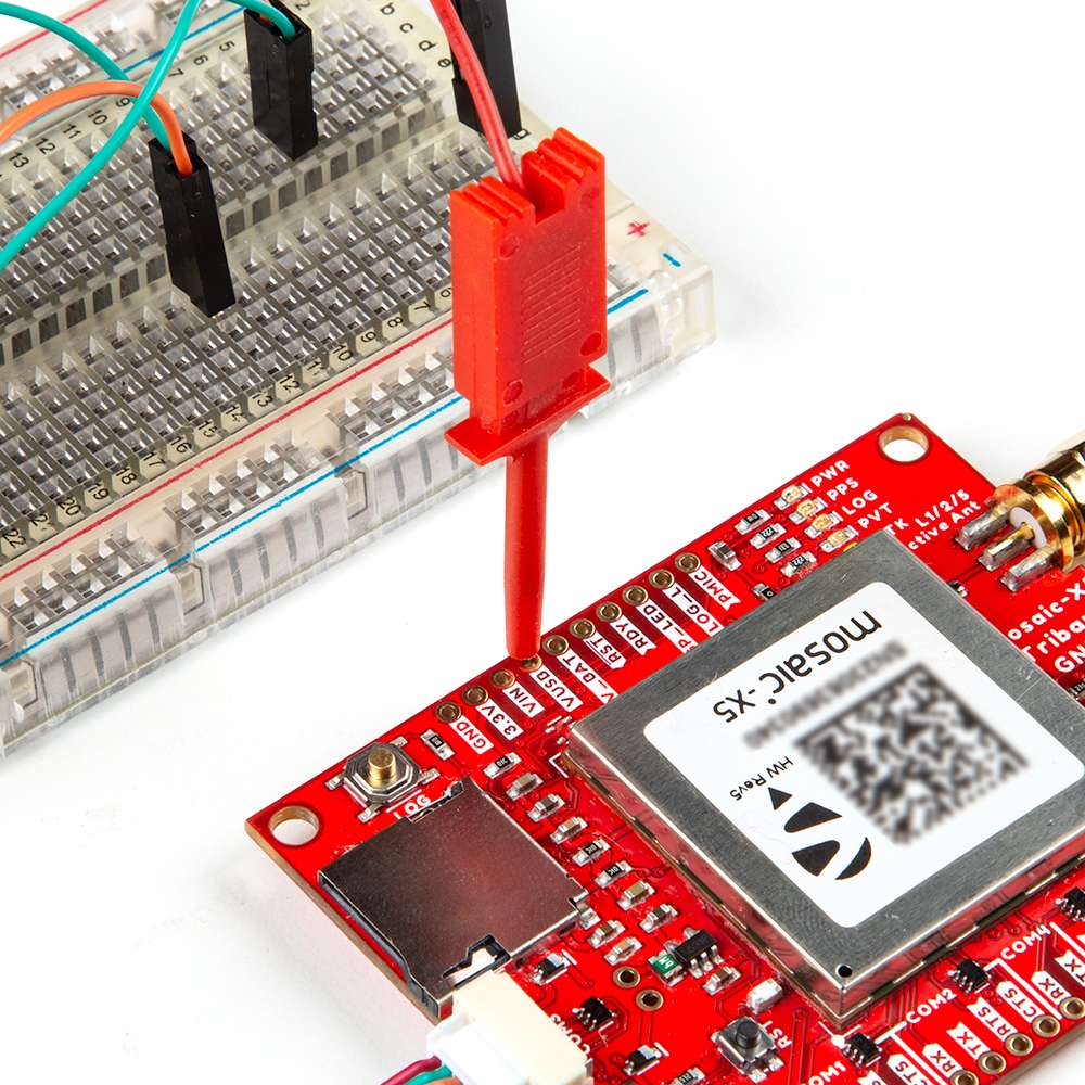
VUSB pin of the Tri-band GNSS RTK breakout board.
In the example displayed below, IC-hook w/ pigtail connects the VUSB pin of the Tri-band GNSS RTK breakout directly to the 5V pin of the LoRaSerial Kit through the breadboard. (Click the images to enlarge, users will notice that the power pin of the radio is wired directly to the VUSB pin of the Tri-band GNSS RTK breakout board.)
VUSB pin of the Tri-band GNSS RTK breakout board.
Breakout Pins
The PTH pins on the Tri-band GNSS RTK board are broken out into 0.1"-spaced pins on the outer edges of the board.
New to soldering?
If you have never soldered before or need a quick refresher, check out our How to Solder: Through-Hole Soldering guide.
-
How to Solder: Through-Hole Soldering
When selecting headers, be sure you are aware of the functionality you require.
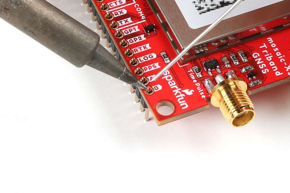
For a more permanent connection, users can solder wires directly to the board.

Software Overview
- <a href="https://www.sparkfun.com/products/25572">
<figure markdown>

</figure>
---
            **iFixit Anti-Static Wrist Strap**<br>
            TOL-25572</a>

        </div>
Note
The mosaic-X5 module has numerous capabilities and a multitude of ways to configure and interface with them. Without regurgitating all the information that is documented in Septentrio's user manuals and videos, we have tried to highlight a good majority of the module's aspects.
With that said, please feel free to file an issue if you feel we have missed something that may benefit other users. (Don't forget to provide us with a link to the documentation and what section the information is located.)
RxTools Software Suite
Tip
Even if you aren't necessarily interested it, we highly recommend that users install the RXTools software suite before plugging in their board. For Windows PCs, it also includes the USB driver for the module that enables the Ethernet-over-USB support and virtual COM ports.
Users should install the RXTools software suite on their computer to interact with the mosaic-X5 module through the USB interface. The software package includes the USB-IP driver1 necessary to recognize the board as an ethernet device on Windows PCs (1).
- On Linux, the standard Linux CDC-ACM driver is suitable.
System Requirements2
- Windows 7
- Windows 8
- Windows 10
- Fedora 23 (or later) using Qt technology.
- The standalone tools (except
bin2asc) will run on older distributions.
- The standalone tools (except
The minimal hardware requirements (1Hz update3):
- CPU: 1 GHz processor
- RAM: 1 GB RAM
- Screen Resolution: 1024×768 or higher resolution
Installation Instructions2
Users can install RxTools software suite by running the installation executable4(1), located in the RxTools\windows directory of the downloaded *.zip file5. During the installation process, users will be notified if a previous version of RxTools is already installed then that the previous version will be uninstalled. Next, users will need to provide an installation directory for the RxTools software suite. Users will then select which of the following applications6 are installed:
- For RxTools v22.1.0, the installation filename is
RxTools_22_1_0_Installer.exefor Windows PCs.
- RxControl
- SBF Converter
- SBF Analyzer
- RxLogger
- RxUpgrade
- RxDownload
- RxPlanner
- Data Link
- RxAssistant
- RxLauncher
Warning
It is recommended that users NOT install RxControl as root, for security reasons and to avoid installation overwrites of other system settings. To make RxTools available to more than one user, provide a shared installation directory.
Users can install RxTools software suite by running the installation binary4(1), located in the RxTools/linux-i386/ directory of the downloaded *.zip file5. During the installation, users will be prompted for an installation directory. If there are any previous installations of RxControl, please use a different directory to avoid conflicts.
- For RxTools v22.1.0, the installation filename is
RxTools_22_1_0_Installer.binfor Linux.
Permission Settings
Once installed, users may need to reconfigure their permission settings:
-
RxTools will need rights to access the
/dev/ttyS*serial ports.-
To access the serial ports, users must be part of the
uucpandlockgroups (1). This can be configured by editing the/etc/group8 file and adding the username to the lines defining theuucpgroup and thelockgroup.For example, when adding the user
jsmithto theuucpgroup, users would modify the/etc/groupfile as shown below: -
On Linux machine administered centrally on a local network, ask your system administrator to be included in the
uucpandlockgroups.
-
-
RxTools also needs read/write (
rw) access(4) to the/dev/ttyS*serial ports.-
Users can change the permissions with the
chmod9 command:
-
- On most Linux operating systems, the
/dev/ttyS*devices are owned byrootand belong to theuucpgroup with read/write (rw) access. Additionally, the devices are normally locked by writing a file in the/var/lock/directory, with the same permissions. - Remove
- Replace with this line
- By default, users will normally have read/write (
rw) access to the/dev/ttyS*serial ports. - where users must specify the port number
e.g./dev/ttyS0might be portCOM1
Note
In order for these changes to take effect, users must update their environment by logging out and back in.
Be aware that the X-session has to be restarted as well. On most systems, this can be done by pressing the key combination Ctrl + Alt + Backspace
64-bit OS
In order to run the RxTools on a 64-bit Linux operating system, users might to install the 32-bit version of the C standard library.
- For Fedora installations, this is the
glibc.i686package. - The equivalent for Debian(/Ubuntu) installations is the
ia32-libspackage.
USB Driver
If users haven't already installed the RxTools software suite on their Windows PC, they will need to install the USB driver1 necessary to recognize and interact with the mosaic-X5 module through the USB interface.
A Windows USB driver for the mosaic-X5 can be installed through two methods:
- RxTools Software Suite (1)
- mosaic-X5 GNSS Receiver Module (2)
- The driver is installed during the installation process.
- The installation file for the Windows USB driver will be available from the mass-storage device when the board is initially connected to the computer.
Once installed, the driver emulates two virtual serial ports, which can be accessed as standard COM ports to the receiver.
Terminal Emulators
Most terminal emulation programs will not make a distinction between virtual or native COM ports. However, for virtual serial ports, the port settings (i.e. baudrate, etc.) are not relevant and the default configuration be used in the terminal emulation program. However, for the physical/native COM ports will have the following default setting:
- Baudrate: 115200bps
- Data Bits: 8
- Parity: No
- Stop Bits: 1
- Flow Control: None
Having Trouble?
For users who are having trouble installing the USB driver, we have an archived version (v3.0.27) of the installation file. Users can download version 3.0.2 of the driver, by clicking on the button below.
On Linux, the standard Linux CDC-ACM driver is suitable.
Web Interface
With the USB driver installed, the mosaic-X5 module supports Ethernet-over-USB. The default IP address allocated for the Ethernet-over-USB interface is 192.168.3.1. This IP can be entered in any browser to open a connection to the receiver's Web Interface as shown below.
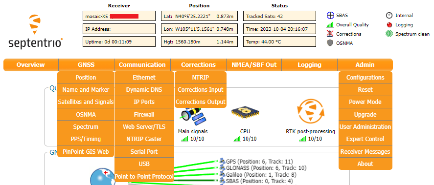
All the drop-down navigation tabs in the web interface.
Info
The default IP address cannot be changed; this feature is only to be used when a single receiver is connected to your computer.
Invalid IP Address (WiFi Only)
One of the documentation pages on Septentrio's website, specifies a default IP address of 192.168.20.1 for the web interface. However, that address is for a WiFi enabled product and cannot be used with this product.
RxTools
            **iFixit Anti-Static Wrist Strap**<br>
            TOL-25572</a>

        </div>
Note
The mosaic-X5 module has numerous capabilities and a multitude of ways to configure and interface with them. Without regurgitating all the information that is documented in Septentrio's user manuals and videos, we have tried to highlight a good majority of the module's aspects.
With that said, please feel free to file an issue if you feel we have missed something that may benefit other users. (Don't forget to provide us with a link to the documentation and what section the information is located.)
RxTools Software Suite
Tip
Even if you aren't necessarily interested it, we highly recommend that users install the RXTools software suite before plugging in their board. For Windows PCs, it also includes the USB driver for the module that enables the Ethernet-over-USB support and virtual COM ports.
Users should install the RXTools software suite on their computer to interact with the mosaic-X5 module through the USB interface. The software package includes the USB-IP driver1 necessary to recognize the board as an ethernet device on Windows PCs (1).
- On Linux, the standard Linux CDC-ACM driver is suitable.
System Requirements2
Operating System
- Windows 7
- Windows 8
- Windows 10
- Fedora 23 (or later) using Qt technology.
- The standalone tools (except
bin2asc) will run on older distributions.
- The standalone tools (except
Hardware Requirements3
The minimal hardware requirements (1Hz update):
- CPU: 1 GHz processor
- RAM: 1 GB RAM
- Screen Resolution: 1024×768 or higher resolution
Installation Instructions2
Users can install RxTools software suite by running the installation executable4(1), located in the RxTools\windows directory of the downloaded *.zip file5. During the installation process, users will be notified if a previous version of RxTools is already installed then that the previous version will be uninstalled. Next, users will need to provide an installation directory for the RxTools software suite. Users will then select which of the following applications6 are installed:
- For RxTools v22.1.0, the installation filename is
RxTools_22_1_0_Installer.exefor Windows PCs.
- RxControl
- SBF Converter
- SBF Analyzer
- RxLogger
- RxUpgrade
- RxDownload
- RxPlanner
- Data Link
- RxAssistant
- RxLauncher
Warning
It is recommended that users NOT install RxControl as root, for security reasons and to avoid installation overwrites of other system settings. To make RxTools available to more than one user, provide a shared installation directory.
Users can install RxTools software suite by running the installation binary4(1), located in the RxTools/linux-i386/ directory of the downloaded *.zip file5. During the installation, users will be prompted for an installation directory. If there are any previous installations of RxControl, please use a different directory to avoid conflicts.
- For RxTools v22.1.0, the installation filename is
RxTools_22_1_0_Installer.binfor Linux.
Permission Settings
Once installed, users may need to reconfigure their permission settings:
-
RxTools will need rights to access the
/dev/ttyS*serial ports.-
To access the serial ports, users must be part of the
uucpandlockgroups (1). This can be configured by editing the/etc/group8 file and adding the username to the lines defining theuucpgroup and thelockgroup.For example, when adding the user
jsmithto theuucpgroup, users would modify the/etc/groupfile as shown below: -
On Linux machine administered centrally on a local network, ask your system administrator to be included in the
uucpandlockgroups.
-
-
RxTools also needs read/write (
rw) access(4) to the/dev/ttyS*serial ports.-
Users can change the permissions with the
chmod9 command:
-
- On most Linux operating systems, the
/dev/ttyS*devices are owned byrootand belong to theuucpgroup with read/write (rw) access. Additionally, the devices are normally locked by writing a file in the/var/lock/directory, with the same permissions. - Remove
- Replace with this line
- By default, users will normally have read/write (
rw) access to the/dev/ttyS*serial ports. - where users must specify the port number
e.g./dev/ttyS0might be portCOM1
Note
In order for these changes to take effect, users must update their environment by logging out and back in.
Be aware that the X-session has to be restarted as well. On most systems, this can be done by pressing the key combination Ctrl + Alt + Backspace
64-bit OS
In order to run the RxTools on a 64-bit Linux operating system, users might to install the 32-bit version of the C standard library.
- For Fedora installations, this is the
glibc.i686package. - The equivalent for Debian(/Ubuntu) installations is the
ia32-libspackage.
Getting Started
Once RxTools have been installed, any of the individual GUI tools can be launched using the RxLauncher application.
When connecting to a receiver using USB, two virtual serial ports will be created on your machine which can be used to communicate to the receiver.
- Check the Device Manager to see the exact names of these virtual serial ports.
- They ports will appear with the name
Septentriowritten beside them.
- They ports will appear with the name
- These virtual serial ports will be labeled as such when RxControl shows the Connection Dialog.
Tip
The virtual serial port names correspond to a given USB port. When plugging the device into a different USB port, the serial port will change.
Once RxControl is installed, it can be launched by executing the link created by the installation program or by executing ./runRxControl in the directory where the program is installed.
- The Data Link and SBF Converter applications should be executed from the
/bindirectory of the installation folder, to ensure that the proper libraries are loaded. Users can also run these applications from the installation directory, in a manner similar to RxControl that is described above. - Other applications can also be executed by launching their appropriate script.
- For example, users can execute
./runDataLinkfrom the/bindirectory, located inside the installation folder.
- For example, users can execute
Web Interface
**iFixit Anti-Static Wrist Strap**<br>
TOL-25572</a>
</div>
Note
The mosaic-X5 module has numerous capabilities and a multitude of ways to configure and interface with them. Without regurgitating all the information that is documented in Septentrio's user manuals and videos, we have tried to highlight a good majority of the module's aspects.
With that said, please feel free to file an issue if you feel we have missed something that may benefit other users. (Don't forget to provide us with a link to the documentation and what section the information is located.)
USB Driver
If users haven't already installed the RxTools software suite on their Windows PC, they will need to install the USB driver1 necessary to recognize and interact with the mosaic-X5 module through the USB interface.
A Windows USB driver for the mosaic-X5 can be installed through two methods:
- RxTools Software Suite (1)
- mosaic-X5 GNSS Receiver Module (2)
- The driver is installed during the installation process.
- The installation file for the Windows USB driver will be available from the mass-storage device when the board is initially connected to the computer.
Once installed, the driver emulates two virtual serial ports, which can be accessed as standard COM ports to the receiver.
Terminal Emulators
Most terminal emulation programs will not make a distinction between virtual or native COM ports. However, for virtual serial ports, the port settings (i.e. baudrate, etc.) are not relevant and the default configuration be used in the terminal emulation program. However, for the physical/native COM ports will have the following default setting:
- Baudrate: 115200bps
- Data Bits: 8
- Parity: No
- Stop Bits: 1
- Flow Control: None
Having Trouble?
For users who are having trouble installing the USB driver, we have an archived version (v3.0.22) of the installation file. Users can download version 3.0.2 of the driver, by clicking on the button below.
On Linux, the standard Linux CDC-ACM driver is suitable.
Web Interface
With the USB driver installed, the mosaic-X5 module supports Ethernet-over-USB. The default IP address allocated for the Ethernet-over-USB interface is 192.168.3.1. This IP can be entered in any browser to open a connection to the receiver's Web Interface as shown below.
All the drop-down navigation tabs in the web interface.
Info
The default IP address cannot be changed; this feature is only to be used when a single receiver is connected to your computer.
Invalid IP Address (WiFi Only)
One of the documentation pages on Septentrio's website, specifies a default IP address of 192.168.20.1 for the web interface. However, that address is for a WiFi enabled product and cannot be used with this product.
Update the Module's Firmware
Latest Firmware
For the latest firmware released by Septentrio, please visit their product page for the mosaic-X5 module.
-
To check for the latest firmware published by Septentrio, please visit their product page for the mosaic-X5 module. Users can click on the button below, to be redirected to the latest firmware for the mosaic-X5.
-
Currently, at the time that this board was released, the firmware for the mosaic-X5 module was v4.15.04. Users can download version 4.15.0 of the firmware, by clicking on the button below.
GPS Data
Besides logging data with just the LOG button, users can configure/enable the output of data streams through the COM ports and data logging to the SD card through the web interface or RxTools software suite. The videos below illustrate how these features can be operated through the web interface.
Related Video
While this instructional video is for a different product line, the information, for the most part, is still relevant.
RTK Corrections
For users with multiple RTK capable GNSS receivers, users can configure their mosaic-X5 as a rover or base station.
Without having to setup a personal base station, users can receive RTK corrections through the internet from 3rd-party services.
Sharing Internet Access
By default, the mosaic-X5 GNSS receiver is not configured to access the internet through the USB interface. In order to receive or cast RTK corrections to/from a RTK network, such as NTRIP, users will need to enable capability.
- Users will need to use the web interface or RxTool software suite to enable the
Outgoing Internet Access Over USBfrom the Communication > USB drop-down menu of the navigation tabs. - This also requires users to allowing Internet sharing through on their computer as well. The procedure to do so depends on your operating system.
- On a Windows PC, users must enable
Allow other network users to connect through this computer's Internet connection, through the properties option of the network adapter with internet access. - On a Linux computer, users will likely need to configure a network bridge.
- On a Windows PC, users must enable
New IP Address
Once a network bridge is enabled, the receiver will receive its IP address from the computer's DHCP server. Depending on the routing table, the module may no longer be reachable at its default IP address (192.168.3.1).
Enable the L5 Band
The mosaic-X5 is capable of utilizing the L5 frequency band. However, within the GPS network, the L5 service isn't completely operational and is currently marked as unhealthy. Users will need to configure the mosaic-X5 to enable the L5 frequency band.
From the Admin tab, navigate through the drop-down menu to Admin > Expert Control > Control Panel > Navigation > Receiver Operation > Masks. Find the Health Masks box, and configure the Discard unhealthy satellites feature to off for both the Tracking and PVT options.
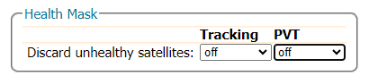
Configuring the Discard unhealthy satellites feature to off.
Note
Make sure to click OK button at the bottom of each page, to save and update the current configuration. Also, the save it to boot option will enable the configuration to persist through power cycles.
From the Navigation tab, navigate through the drop-down menu to Navigation > Advance User Settings > Tracking > Signal Tracking. Find the Signal Tracking box, then enable the GPSL5 option.
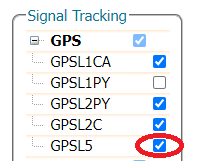
Enabling signal tracking of the L5 frequency band for the GPS constellation.
Click OK
Don't forget to click OK button at the bottom of the page to save and update the current configuration.
Again in the Navigation tab, navigate to Navigation > Advance User Settings > PVT > Signal Usage. Enable the GPSL5 option in both Signals enabled in the PVT and Signals enabled in the navigation data decoder sections.
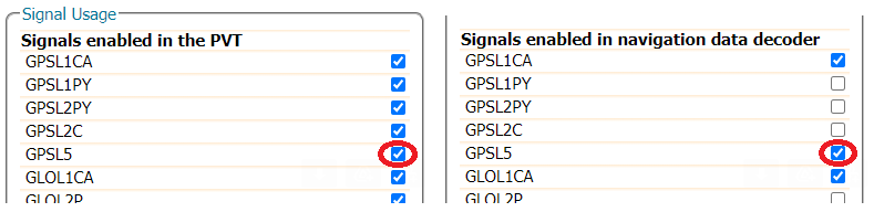
Enabling signal usage of the L5 frequency band for the GPS constellation.
Click OK
Don't forget to click OK button at the bottom of the page to save and update the current configuration.
More Videos
Users can find other instructional videos on Septentrio's YouTube Channel. Feel free to check out their playlists as well:
Other Videos
Troubleshooting Tips
Need Help?
If you need technical assistance or more information on a product that is not working as you expected, we recommend heading on over to the SparkFun Technical Assistance page for some initial troubleshooting.
If you can't find what you need there, the SparkFun Forums is a great place to search product forums and ask questions.
Account Registration Required
If this is your first visit to our forum, you'll need to create a Forum Account to post questions.
Electrostatic Discharge
The mosaic-X5 module is sensitive to ESD. Use a proper grounding system to make sure that the working surface and the components are at the same electric potential.
ESD Precaution
As recommended by the manufacturer, we highly recommend that users take the necessary precautions to avoid damaging their module.
-
-
The Tri-band GNSS RTK breakout board features ESD protection on the USB-C connector and breakout's I/O:
- USB data lines
- I/O PTH pads
- JST connector's pins
-
The mosaic-X5 module features internal ESD protection to the
ANT_1antenna input.
-
USB Driver
A USB driver is only required for Windows PCs (see the USB Driver section).
GPS Antenna
Power Input
Active Antenna
Never inject an external DC voltage into the SMA connector for the GPS antenna, as it may damage the mosaic-X5 module. For instance, when using a splitter to distribute the antenna signal to several GNSS receivers, make sure that no more than one output of the splitter passes DC. Use DC-blocks otherwise.
A 3 - 5.5V DC voltage can be applied to the main antenna from the VANT pin, obviating the need for an external antenna supply or bias-tee.
Supported Frequency Bands
For the best performance, we recommend users choose a compatible L1/L2/L5 (tri-band) GNSS antenna and utilize a low-loss cable. Utilizing an antenna that doesn't match all the supported frequency bands of the mosaic-X5, will result in reduced performance and capabilities.
Data Logging
For data logging issues, here are some simple troubleshooting tips:
- Make sure that your SD card is formatted to a
FAT32file system.- The
FAT32file system also limits the maximum capacity of the card to less than 32GB (i.e. a 256GB SD card will not work).
- The
- Make sure that the mosaic-X5 module has a configured data stream output.
- Use the mosaic-X5 web page to verify that the SD card is mounted as a storage drive.
Resources
Product Resources
- Product Page
- Design Files:
- Component Documentation
- SFE Product Showcase
- Hardware Repo
Additional Resources
🏭 Manufacturer's Resources
Septentrio also provides great resources for the mossaic-X5 GNSS receiver module:
- mosaic-X5 Product Page
- Septentrio YouTube Channel
- Support Page
- Technical Support Portal
- Learn More
- Webinars
- Technical Papers
- Insights (Case Studies and Technical Articles)
- Community
- Agnostic Corrections Program
- JammerTest 2023 - Anti-Jamming and Anti-Spoofing Performance

Background Resources
Below, are several articles, application notes, and other technical resources:
-
Manufacturer Resources
- GPS / GNSS correction services
- AIM+ anti-jamming and anti-spoofing protection
-
Webinars
-
NGS: User Guidelines for Single Base Real Time GNSS Positioning
- International Association of Geodesy: Sub-Commission 4.5 - Next Generation RTK
-
On Linux, the standard Linux CDC-ACM driver is suitable. ↩↩↩↩↩↩
-
For the latest USB driver from Septentrio, please install their driver through the RxTools software suite.
This is driver version, was archived at the time that this guide was written. Please do not request for the file to be updated. ↩↩↩↩↩ -
Higher data rates will require higher CPU speed and more memory capacity. ↩↩
-
For the latest firmware published by Septentrio, please visit their product page.
This is firmware version, was archived at the time that this guide was written. Please do not request for the file to be updated; instead visit the product page to download the latest firmware. ↩↩↩↩↩ -
Users may need to extract the RxTools installation files from the downloaded, compressed file. ↩↩↩↩
-
Please see the release notes for the issues and limitations of the RxTools applications. ↩↩
-
For the latest USB driver from Septentrio, please install their driver through the RxTools software suite.
This is driver version, was archived at the time that this guide was written. Please do not request for the file to be updated. ↩ -
Changing these permissions also requires
rootprivileges. ↩↩