Introduction
Info
This tutorial is an update to the BNO080. If you are looking for the original tutorial for the BNO080, make sure to head to the Qwiic VR IMU (BNO080) Hookup Guide. Note that the BNO080 is EOL. Additionally, this tutorial uses a different Arduino Library.
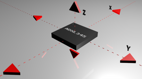
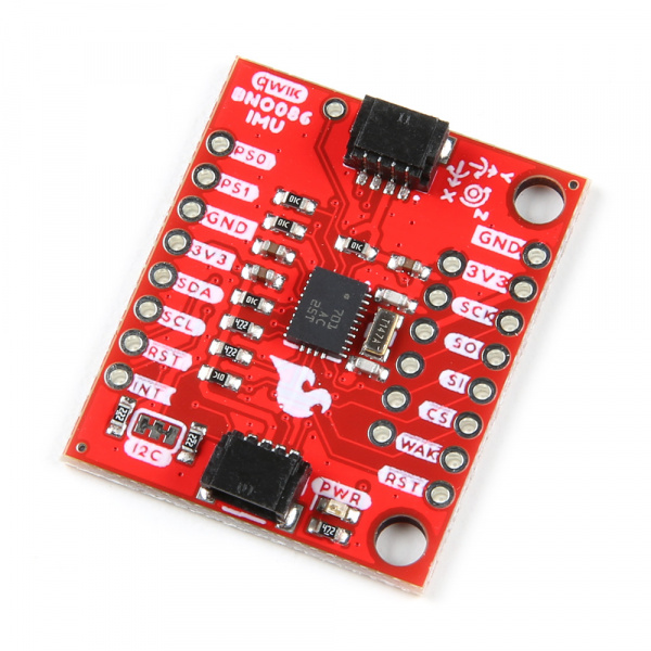
CEVA's BNO086, a combination triple-axis accelerometer/gyro/magnetometer System in Package (SiP), packaged with a 32-bit ARM© Cortex™ M0+. The BNO086 Inertial Measurement Unit (IMU) produces accurate rotation vector headings, excellently suited for VR and other heading applications, with a static rotation error of two degrees or less. The VR IMU is exactly what we’ve been waiting for: all the sensor data is combined and drift-corrected into meaningful, accurate IMU information. It’s perfect for any project that needs to sense orientation or motion. We've taken this IMU and stuck it on a Qwiic enabled breakout board, in order to make interfacing with the tiny, QFN package a bit easier to connect.
In this hookup guide, we'll connect our sensor up to our microcontroller of choice and separately read the rotation vectors (which is what we will mainly want), acceleration vectors, gyro values, and magnetometer vectors. We'll check out how to implement the step counter on the BNO086 in order to use it as a pedometer. We'll also read Q values from the sensor. Knowing what activity you're performing is important so we'll learn how to classify what activity the IMU is performing (i.e. Sitting still, moving, biking, walking, running, etc...) and how confident the IMU is that each activity is being performed. Printing out raw packets will also be examined for debugging purposes. Finally, we'll examine how to configure the sensor on different I2C ports and addresses. A bonus example is provided in Processing to show us how to use quaternion data to orient a cube.
Required Materials
To follow along with this tutorial, you will need the following materials. You may not need everything though depending on what you have. Add it to your cart, read through the guide, and adjust the cart as necessary.
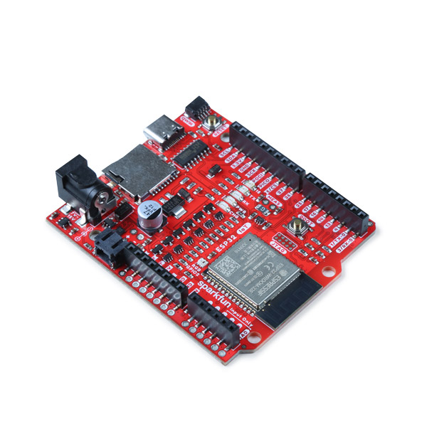
- 1x SparkFun IoT RedBoard - ESP32 Development Board [WRL-19177]
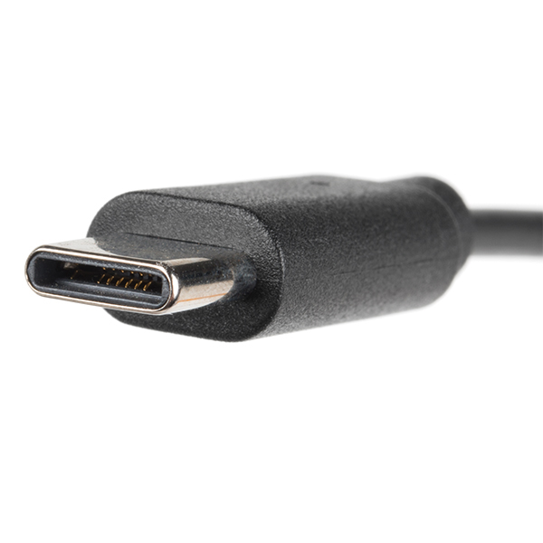
- 1x USB-C cable
- Our USB 2.0 A to C Cable [CAB-15092] will do nicely
- Our USB 3.1 A to C Cable [CAB-14743] is a good choice too
- 1x SparkFun VR IMU Breakout - BNO086 (Qwiic) [SEN-22857]
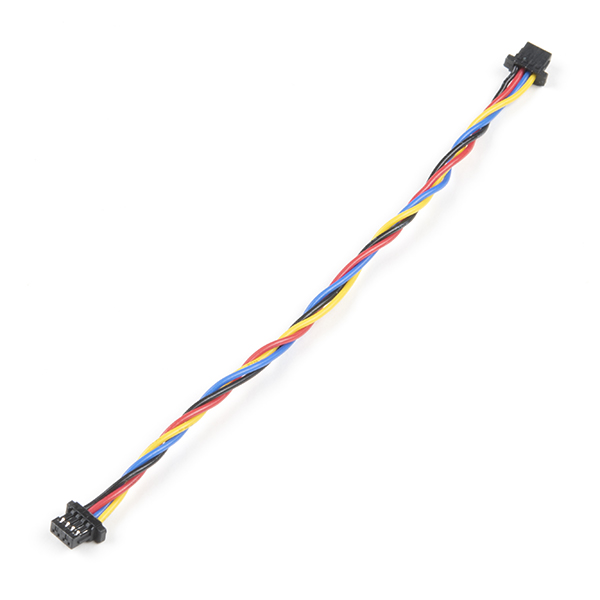
- 1x Qwiic Cable
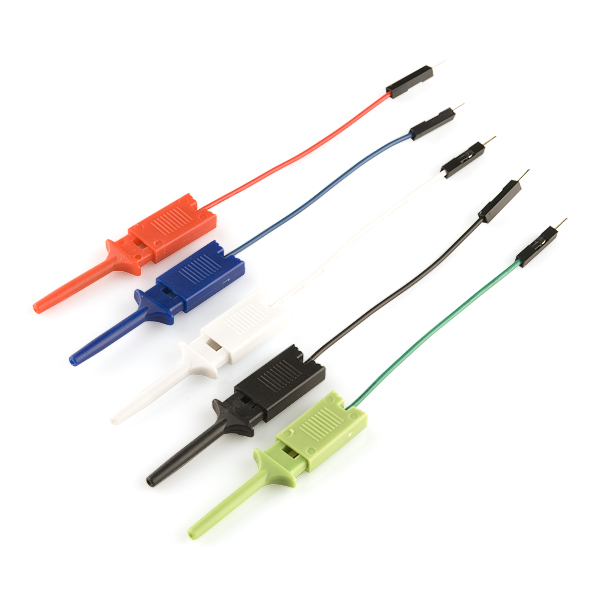
- 2x IC Hooks (optional for advanced configuration)
- The pack of 5x IC Hook with Pigtail [CAB-09741] for a temporary connection
Note
As of Arduino Library v1.0.3, the BNO086 has also been tested to work with a SAMD51 (i.e. SparkFun Thing Plus - SAMD51) as well!
Tools
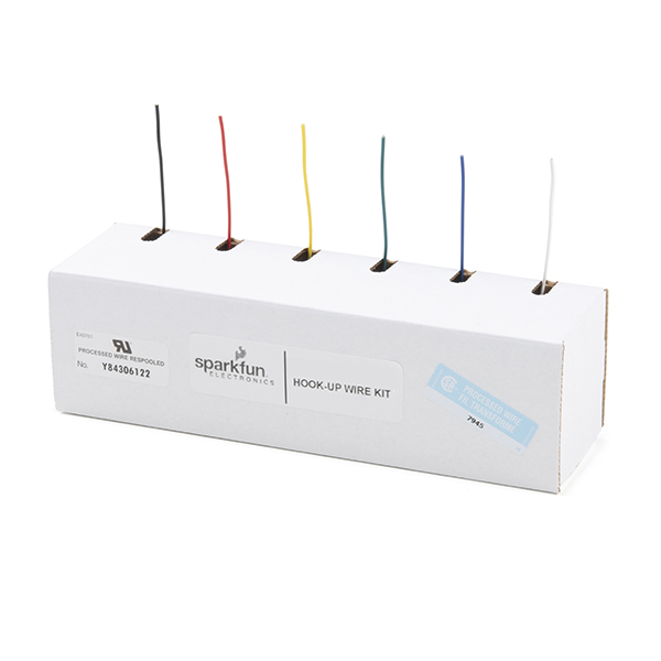
For a secure connection when connecting to the reset and interrupt pins, you will need to solder two wires between your microcontroller and the breakout board. This requires some assembly and soldering. You may already have a few of these items but if not, the tools and hardware below help with that assembly.
- Hook-Up Wire - Assortment (Stranded, 22 AWG) [PRT-11375]
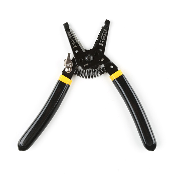
- Wire Stripper - 20-30 AWG Solid (22-32 AWG Stranded) [TOL-22263]
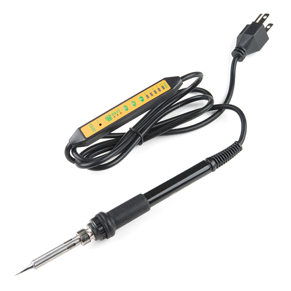
- Soldering Iron [TOL-14456]
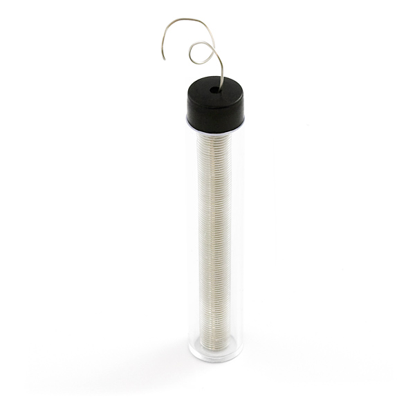
- Solder Lead Free - 15-gram Tube [TOL-9163]
Suggested Reading
If you aren't familiar with the Qwiic Connection System, we recommend reading here for an overview.

If you aren’t familiar with the following concepts, we also recommend checking out a few of these tutorials before continuing.