RTK Base
Commercial RTK correction services are great. But there will be times when you want to generate your own correction data so you can share it with your Rover(s) with the shortest baselines. Put simply, an RTK Base knows where it is and - based on its location - can share satellite signal correction data with local Rovers, to allow them to achieve centimeter-level positioning.
For RTK to work, the Base station antenna location is needed to calculate an accurate and reliable position. How do we do that?
In this section, we discuss two different ways of establishing the Base station antenna position: temporary and fixed.
Temporary Base
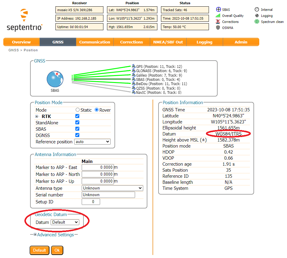
The mosaic-X5 can be set to "Static" mode and can determine the antenna location (reference position) automatically. This is equivalent to "Survey-In" on u-blox GNSS modules. The module will refine its estimate of the antenna position and use that to generate correction data for Rovers.

Info
In this mode the module refines its estimate of the antenna position; a new antenna position will be calculated each time the mosaic-X5 is restarted. For this reason, the auto function should only be used to generate a temporary base antenna location.
Fixed Base
The best way to determine the base antenna location is to: log raw GNSS signal data for typically 24 hours, convert it to RINEX format and then submit it to a Precise Point Positioning (PPP) post-processing service such as:
There are some great articles written about PPP. Here we are just covering the essentials. For more information check out:
Once the precise antenna position is known, it can be programmed into the module. The corrections the module generates will then be based on that precise, fixed antenna position.
First, let's check what Datum the module is using. It defaults to WGS84/ITRS. In North America, it might be better to select NAD83 but here we'll go with the default.
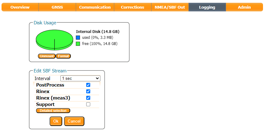
Set up an SBF logging stream to log PostProcess, Rinex, Rinex (meas3) with an interval of 1 sec:

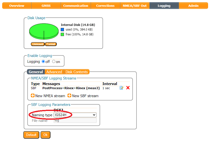
The IGS24H Naming Type is useful. When selected, the mosaic-X5 will log data in intervals of 24 hours, opening a new file at UTC midnight.
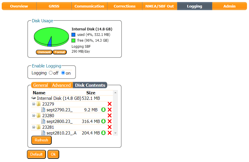
Use the Enable Logging radio button to start logging data, or press the LOG pushbutton. The red LOG LED will blink while data is being logged.
Use the Disk Contents tab to download the SBF data to your computer. Click the green arrow to download an individual file. Or - if the file is large - dismount the disk, eject it and use your computer to copy the files from microSD manually.
Use the RxTools SBF Converter utility to convert the data to RINEX format.

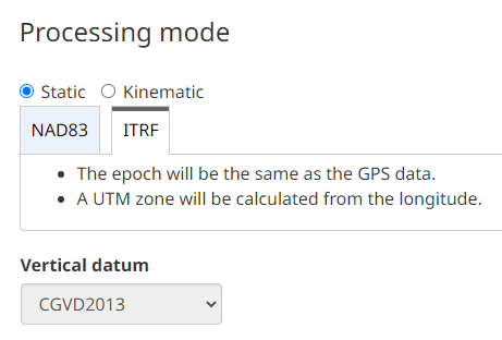
Upload the RINEX data to your chosen PPP post-process service. We have found NRCAN is very easy to use and produces excellent results. We select the ITRF tab because we are using the WGS84/ITRS datum. (If you are using NAD83, select that tab instead.)
After you have uploaded your RINEX data, it only takes a few minutes to receive your antenna position:

Both OPUS and APPS have file size limits. You can shrink the size of the RINEX file by selecting (e.g.) a 30-second Epoch Interval in SBF Converter:

Using a smaller, 30-second file OPUS' ITRF results match NRCAN to within a cm:

We can now store those coordinates in the mosaic-X5 module memory, either as Geodetic (Latitude, Longitude, Altitude) or Cartesian (ECEF X/Y/Z) coordinates. The mosaic-X5 allows you to store 5 of each.


We can now generate corrections using that static / fixed antenna position.
