Introduction
-
-
Designed and manufactured in Boulder, Colorado, USA, the SparkFun RTK mosaic-X5 is the perfect solution for your high-precision positioning and navigation needs. Based around the multi-constellation, multi-frequency, L5-ready mosaic-X5 from Septentrio, this is our most advanced RTK product to date. It supports GNSS signals from GPS (USA), GLONASS (Russia), Beidou (China), Galileo (Europe), Navic (India) plus special additional satellites (e.g. SBAS and QZSS). The mosaic-X5 also has built-in on-module support for other L-band correction services.
The RTK mosaic-X5 can be configured as a Real-Time Kinematic (RTK) Base, where it feeds corrections to other RTK Rovers, or as an RTK Rover where it can use corrections to achieve a horizontal positioning accuracy of 6 millimeters (0.6cm) (plus 0.5 PPM). For applications like robotics and autonomous systems, the mosaic-X5 can deliver position updates at 100Hz (100 times per second). The mosaic-X5 is a very sophisticated chip running a full internal web page server; the position can be monitored and the module is fully configured through that web page using a standard browser.
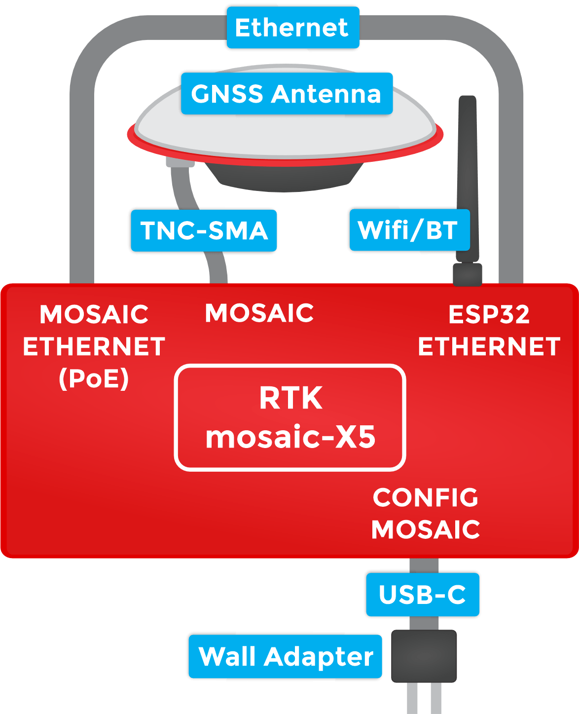
Under the hood, the RTK mosaic-X5 is powered by the mosaic-X5 GNSS module from Septentrio; and the Espressif ESP32-WROVER processor (16MB flash, 8MB PSRAM). The mosaic-X5 has USB-C connectivity (with Ethernet-over-USB), multiple UARTs and supports full Ethernet connectivity. The only interface it doesn't offer is WiFi and that's why we've included the ESP32 with its own Ethernet connection. You can connect the mosaic-X5 directly to your Ethernet network - our product supports Power-over-Ethernet too. Or you can link the mosaic-X5 Ethernet port to the ESP32 Ethernet port and have the ESP32 provide WiFi connectivity. In that mode, the ESP32 becomes an Ethernet to WiFi Bridge, seamlessly passing WiFi traffic to and from the mosaic-X5 via Ethernet.
 Purchase from SparkFun
 Product Comparison
Below is a simple comparison table between our mosaic-X5 products and Septentrio's development and evaluation kits:
mosaic-X5 Development Kit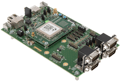
|
mosaic-go Evaluation Kit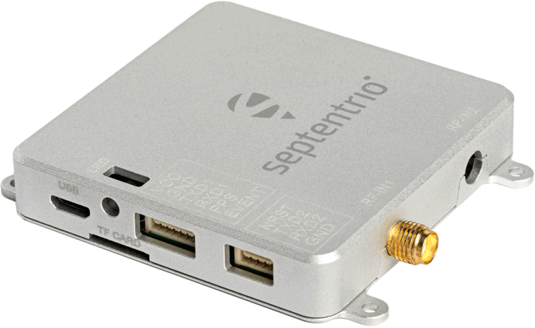
|
mosaic-X5 GNSS Breakout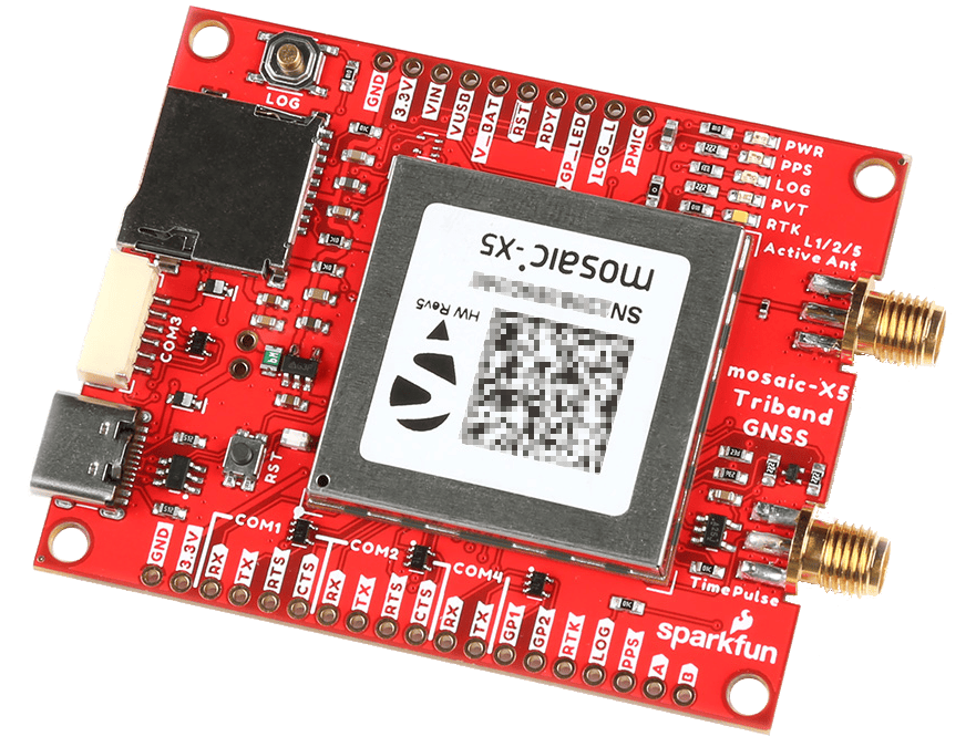
|
RTK mosaic-X5
|
mosaic-X5 Flex Module
|
SparkPNT RTK Facet mosaic
|
|
|---|---|---|---|---|---|---|
| GNSS Antenna | Dual |
Single (mosaic-X5) Dual (mosaic-H) |
Single | Single | Single | Integrated |
| USB Connector | micro-B | micro-B | Type-C | Type-C | N/A* | Type-C |
| Ethernet |
Yes 10/100 Base-T |
No | No |
Yes 10/100 Base-T |
2x10 Header* | No |
| WiFi | No | No | No |
Yes - Network Bridge 10 Base-T |
No |
Yes - Network Bridge 10 Base-T |
| COM Ports | 4 | 2 | 4 |
1 - mosaic-X5 1 - ESP32 |
4 |
1 - mosaic-X5 1 - ESP32 |
| µSD Card Slot | Yes | Yes | Yes | Yes | 2x10 Header* | Yes |
| Reset/Log Buttons | Yes | No* | Yes | Yes | No | Yes |
| Logic-Level |
1.8V 3.3V |
3.3V | 3.3V |
3.3V 5V |
3.3V | 3.3V |
| PPS Signal | Header Pin | 6-Pin JST Connector | SMA Connector | Screw Terminal | 2x10 Header* | No |
| Enclosure Material | N/A | Metal | N/A | Aluminum | N/A | Plastic |
| Dimensions | N/A | 71 x 59 x 12mm ± 1mm | 70.9 x 50.8 x 8mm |
180.6 x 101.8 x 41mm Enclosure Only |
||
| Weight | N/A | 58g ± 1g | 22.6g |
415.15g Enclosure Only |
mosaic-go Evaluation Kit
The reset pin is exposed on 4-pin JST connector and the log pin is connected to the latch pin of the SD card slot.
mosaic-5 Flex Module
SparkPNT GNSS Flex modules are modular, plug-in boards that utilize a carrier board to access the pins of the GNSS Flex headers.
Required Materials
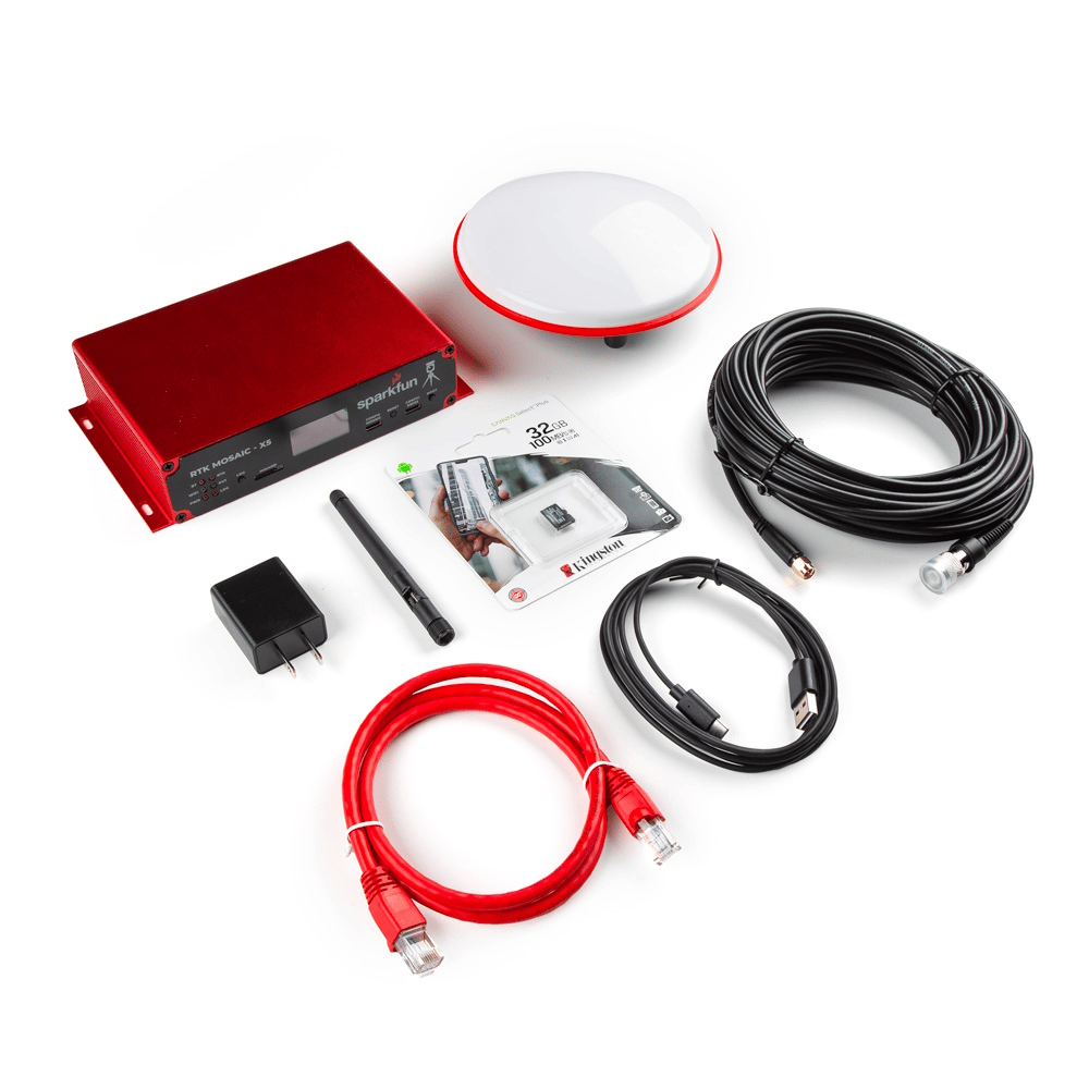
The RTK mosaic-X5 comes with everything you need to get up and running.
Kit Contents
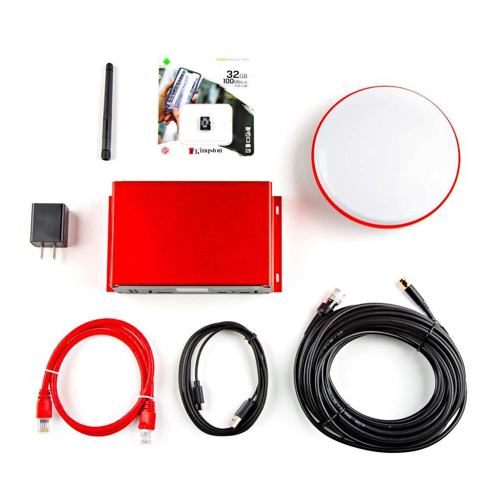
Everything that is included in the RTK mosaic-X5 kit.
- The linked product does not include the front/rear panels and stickers from the RTK mosaic-X5.
Mounting Hardware
This kit does not include any mounting hardware for the antenna. If you wish to permanently mount the antenna outside, we recommend the following products:
-

GNSS Antenna Mounting Hardware Kit
KIT-22197 -
GNSS Magnetic Antenna Mount - 5/8" 11-TPI
PRT-21257
Extension Cables
Your RTK mosaic-X5 is equally at home on your desk, lab bench or in a server rack. But you're still going to want to put the GNSS antenna outdoors, so it will have the best view of the sky. Some extra SMA extension cables may be useful and we have good quality low-loss RG58 cables available in the store. The GNSS SMA antenna connection is standard polarity. If you want to extend the ESP32 WiFi / BT antenna connection too, you need a Reverse Polarity (RP) cable for that.
-
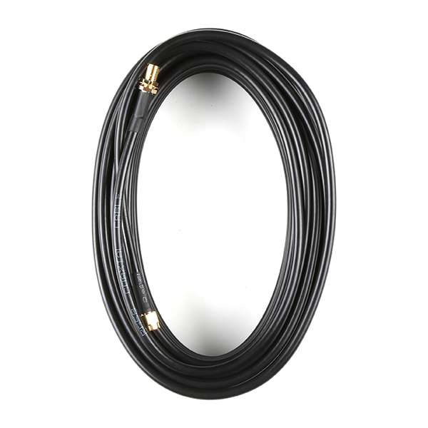
Interface Cable - SMA Female to SMA Male (10m, RG58)
CAB-21281Tip
Use this extension cable for the GNSS antenna. This cable will not work with the WiFi/BLE antenna due to the polarity of the connectors.
-
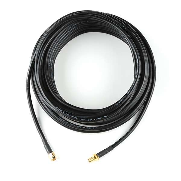
Interface Cable - RP-SMA Male to RP-SMA Female (10M, RG58)
CAB-22038Tip
Use this extension cable for the WiFi/BLE antenna. This cable will not work with the GNSS antenna due to the polarity of the connectors.
Selecting an Outdoor Enclosure
The RTK mosaic-X5 comes in a beautiful custom extruded aluminum enclosure, with machined end panels and matching stickers. The slotted flanges make it easy to install and secure the enclosure in many locations. But the enclosure only provides limited protection against the ingress of dust and water; it is IP42. So, if you are going to permanently install it up on the roof too, you're going to need a suitable weatherproof box. We found a good one - the Orbit 57095 - also available from Amazon - back when we put together our very first DIY GNSS Reference Station.
-
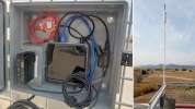
How to Build a DIY GNSS Reference Station
AC Not Required!
The Orbit enclosure comes with a built-in power outlet, but you don't need it! The RTK mosaic-X5 can be powered by Power-over-Ethernet (PoE), meaning all you really need to run up to the roof is a standard 8-core CAT-6 Ethernet cable. Choose a PoE Ethernet Switch that meets your needs. We have had good experiences with the TP-Link TL-SG1005P - available from many retailers including Amazon.
Suggested Reading
As a more sophisticated product, we will skip over the more fundamental tutorials (i.e. Ohm's Law and What is Electricity?). However, below are a few tutorials that may help users familiarize themselves with various aspects of the board.
-
GPS Basics
-

What is GPS RTK?
-

Setting up a Rover Base RTK System
-
How to Build a DIY GNSS Reference Station
-
mosaic-X5 GNSS Breakout Board Hookup Guide
-

Qwiic OLED 1.3" Hookup Guide
-
How to Install CH340 Drivers
-

Serial Terminal Basics
-

Logic Levels
-
I2C
-
Serial Communication
-

How to Work with Jumper Pads and PCB Traces
Related Blog Posts
Additionally, users may be interested in these blog post articles on GNSS technologies:
-

GPS vs GNSS
-

What is Correction Data?
-

Real-Time Kinematics Explained
-

DIY RTK Surveying
-
New Video: Unlocking High-Precision RTK Positioning
Quick Start Guide
Directions
This quick start guide is intended to help users get started with their RTK mosaic-X5, without having to review the technical details of the product. It includes the minimum instructions to initially set up the RTK mosaic-X5, depending on the primary interface that users would like to utilize:
- Ethernet
-
Instructions to connect the RTK mosaic-X5 to a network with an ethernet cable. This will provide the mosaic-X5 with network connectivity for its web server. Users can then pull up the configuration web page from any computer connected to that network.
- WiFi
-
Instructions for remote/exterior installations, where a WiFi connection is preferred. This will provide WiFi connectivity to mosaic-X5's web server; where users can then access the configuration web page from any device on the WiFi network.
- USB-C
-
For users that just want to interface and set up the RTK mosaic-X5, directly through their computer.
Quick Start Pamphlet
For users who have lost the pamphlet in their kit, please check out the links below to download the *.pdf file:

*.pdf file of the quick start pamphlet.
The simplest way to get your RTK mosaic-X5 up and running is to connect it to your Ethernet network or an Ethernet port on your broadband router:
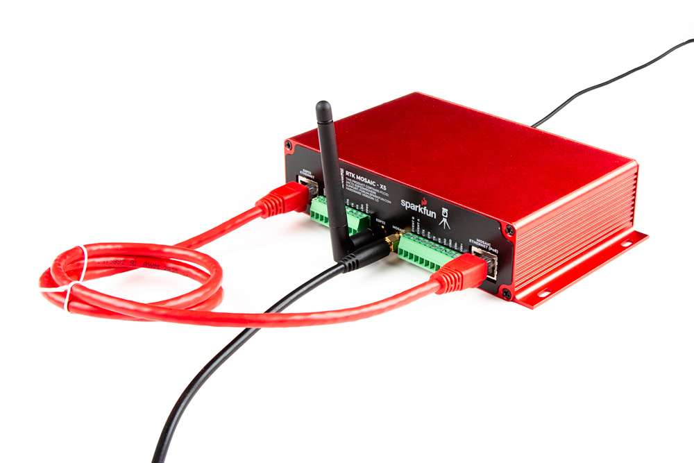
1- Connect the GNSS antenna-
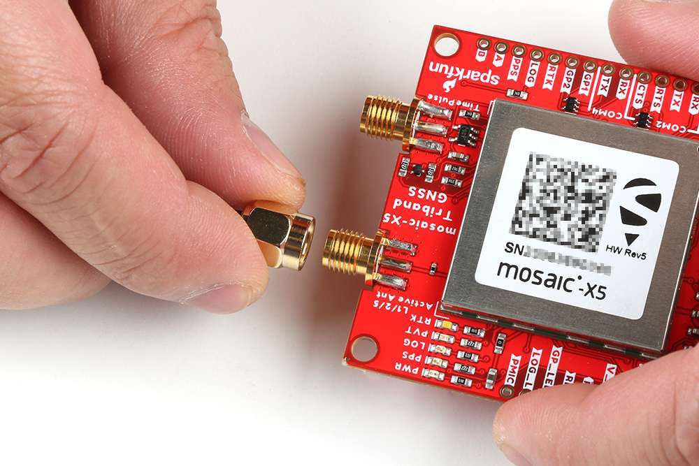
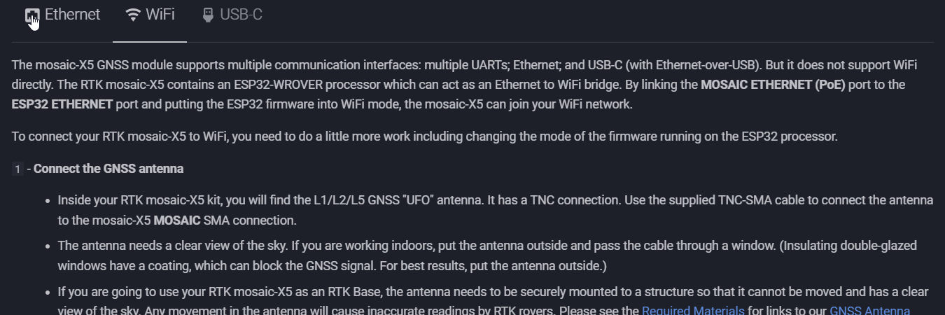
- Inside your RTK mosaic-X5 kit, you will find the L1/L2/L5 GNSS "UFO" antenna. It has a TNC connection. Use the supplied TNC-SMA cable to connect the antenna to the mosaic-X5 MOSAIC SMA connection.
- The antenna needs a clear view of the sky. If you are working indoors, put the antenna outside and pass the cable through a window. (Insulating double-glazed windows have a coating which can block the GNSS signal. For best results, put the antenna outside.)
- If you are going to use your RTK mosaic-X5 as an RTK Base, the antenna needs to be securely mounted to a structure so that it cannot be moved and has a clear view of the sky. Any movement in the antenna will cause inaccurate readings by RTK rovers. Please see the Required Materials for links to our GNSS Antenna Mounting Hardware Kit and GNSS Magnetic Antenna Mount - 5/8" 11-TPI
2- Connect the RTK mosaic-X5 to your Ethernet network or router-
- Use the supplied CAT-6 Ethernet cable to connect the MOSAIC ETHERNET (PoE) port to your network or an Ethernet port on your router.
- If your router provides Power-over-Ethernet (PoE), you're all set! You should see the red power (PWR) LED light up and text start to scroll up the OLED display.
- If your router does not provide PoE, move on to step 3.
3- Provide power-
- You can power the RTK mosaic-X5 using the supplied USB power supply (5V 1A wall adapter).
- Plug the power supply into the wall.
- Use the supplied USB-C cable to connect the power supply to either the CONFIG MOSAIC or the CONFIG ESP32 USB-C port. It does not matter which.
- You should see the red power (PWR) LED light up and text start to scroll up the OLED display.
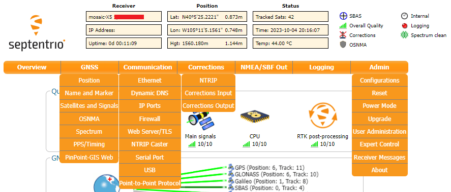
Once the mosaic-X5 has acquired a satellite signal and is connected to the Ethernet network, the OLED will display: the antenna's position as Latitude (Lat), Longitude (Long) and Altitude (Alt); the Ethernet IP (Internet Protocol) network address.
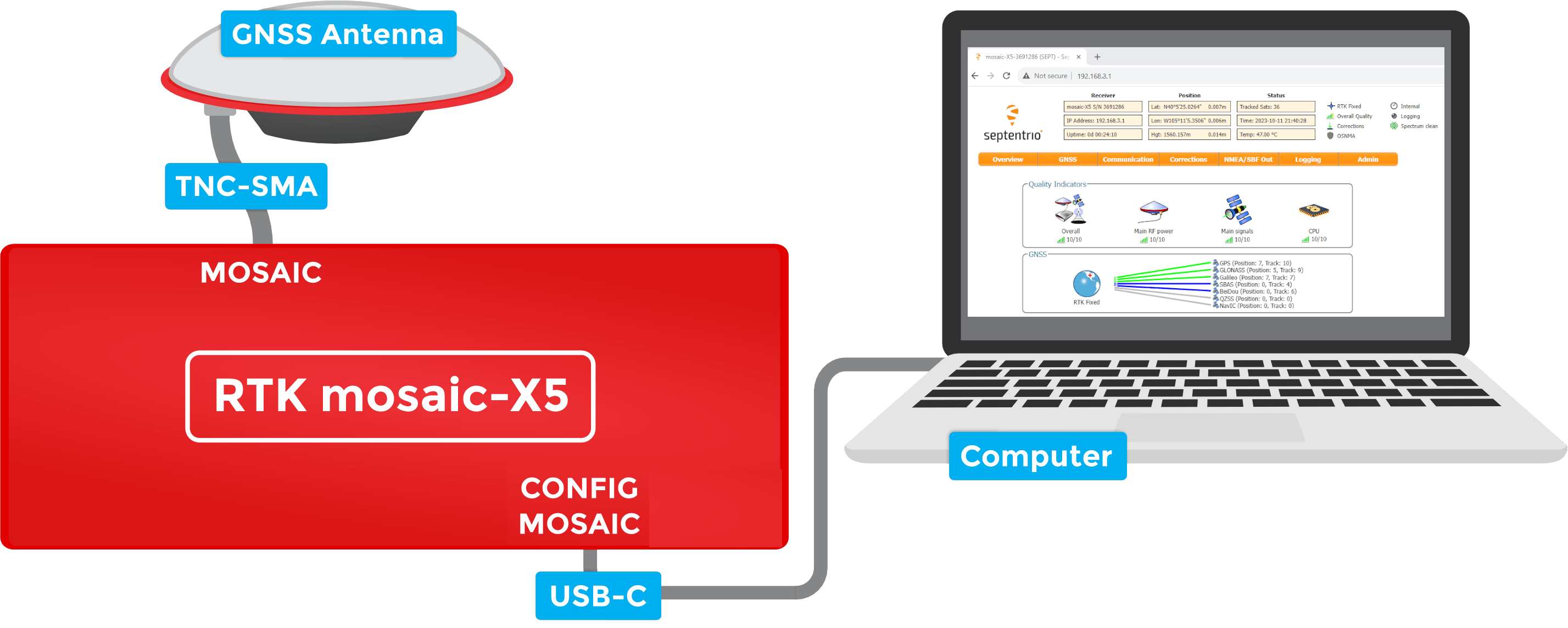
Connect your computer, tablet or phone to the same network, open a web browser and navigate to the IP address shown on the OLED display. You should see the mosaic-X5's internal web page. The web page displays a lot of helpful information and can also be used to fully configure the mosaic-X5.

Not working?
The following sections will help if your RTK mosaic-X5 is not working as expected:
Using mosaic-X5 firmware >= 4.15.1?
With mosaic-X5 firmware 4.15.1, a user-defined username and password are mandatory on all IP interfaces. These must be entered as described in the Log-in procedure on all IP interfaces individually and separately. The ESP32 is connected via COM. It does not need to know the username and password unless you also change default access level for the COM ports. If you do, you need to ensure the RTK mosaic-X5 ESP32 firmware has been upgraded to version >= 1.0.5 and that the username and password have been set using set -u and set -x
No power?
The red power (PWR) LED will light up when the RTK mosaic-X5 has power. If the PWR LED is off, make sure the wall adapter has power and the USB cable is connected.
If you use your own Ethernet cable for Power-over-Ethernet, check it has all eight pins connected. Some cables only have four pins connected and do not support Power-over-Ethernet.
No position information?
The OLED display will only show position information (Lat, Long, Alt etc.) once a satellite signal has been acquired. If you see only the IP address on the display, check the SMA to TNC cable is connected correctly and that the antenna is outside with a clear view of the sky. Use a male-female SMA extension cable if needed to increase the cable length.
No IP address?
By default, the mosaic-X5 Ethernet port is configured for Dynamic Host Configuration Protocol (DHCP). It expects the router / Ethernet switch to provide it with an IP address. If the IP address is all zeros (0.0.0.0), check that your router has DHCP enabled. Most do.
If you need a static IP address, you can configure this through the mosaic-X5's Communication Ethernet sub-page.
Subnet 3 is reserved for the mosaic-X5's USB-C connection (Ethernet-over-USB). If your router / switch is allocating addresses using subnet 3 (192.168.3.***), please change its settings so it uses a different subnet.
No web page?
If you can not see the mosaic-X5's internal web page, please check that your computer / tablet / phone is connected to the same network. Most broadband routers support both Ethernet and WiFi simultaneously using the same subnet. If you are using a phone, check it is connected to the router WiFi - and not using its mobile data connection.
Subnet 3 is reserved for the mosaic-X5's USB-C connection (Ethernet-over-USB). If your router / switch is allocating addresses using subnet 3 (192.168.3.***), please change its settings so it uses a different subnet. If it is using subnet 3, both the mosaic-X5 and your device will appear to have valid IP addresses but will not be able to communicate.
Wrong mode?
If you still can not see the mosaic-X5's internal web page, please check that the ESP32 firmware is in the correct mode. Press the RESET button to restart the ESP32 and watch the text, which scrolls up the OLED display. You should see Mode 1: Ethernet displayed briefly. If you see Mode 2: WiFi, the firmware is in the wrong mode. Follow the instructions in the next section to change the mode back to 1 (Ethernet).
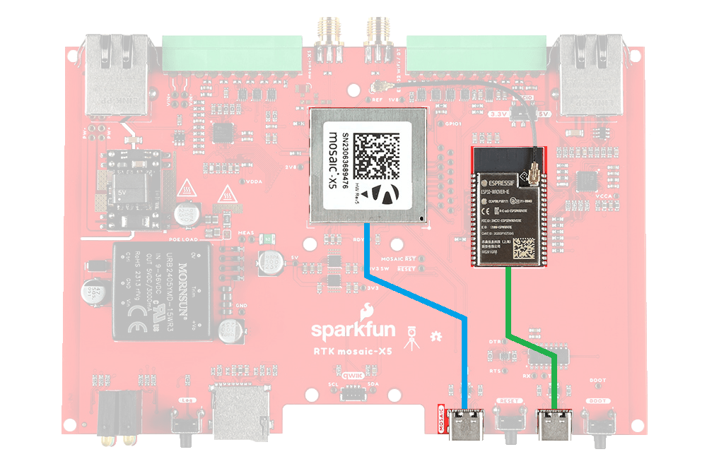
The mosaic-X5 GNSS module supports multiple communication interfaces: multiple UARTs; Ethernet; and USB-C (with Ethernet-over-USB). But it does not support WiFi directly. The RTK mosaic-X5 contains an ESP32-WROVER processor which can act as an Ethernet to WiFi bridge. By linking the MOSAIC ETHERNET (PoE) port to the ESP32 ETHERNET port and putting the ESP32 firmware into WiFi mode, the mosaic-X5 can join your WiFi network.
To connect your RTK mosaic-X5 to WiFi, you need to do a little more work including changing the mode of the firmware running on the ESP32 processor.
1- Connect the GNSS antenna-
- Inside your RTK mosaic-X5 kit, you will find the L1/L2/L5 GNSS "UFO" antenna. It has a TNC connection. Use the supplied TNC-SMA cable to connect the antenna to the mosaic-X5 MOSAIC SMA connection.
- The antenna needs a clear view of the sky. If you are working indoors, put the antenna outside and pass the cable through a window. (Insulating double-glazed windows have a coating, which can block the GNSS signal. For best results, put the antenna outside.)
- If you are going to use your RTK mosaic-X5 as an RTK Base, the antenna needs to be securely mounted to a structure so that it cannot be moved and has a clear view of the sky. Any movement in the antenna will cause inaccurate readings by RTK rovers. Please see the Required Materials for links to our GNSS Antenna Mounting Hardware Kit and GNSS Magnetic Antenna Mount - 5/8" 11-TPI
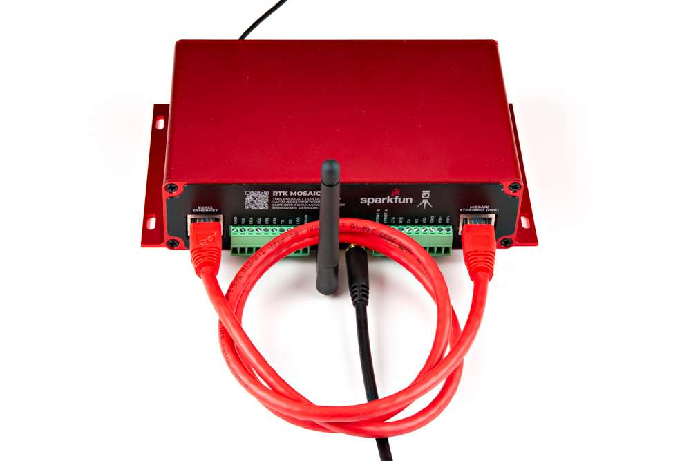
2- Attach the WiFi antenna-
- Screw the supplied WiFi/BT antenna onto the ESP32 SMA connection.
- To minimize wear of the SMA connector, we recommend: holding the antenna body with one hand - to prevent it from rotating - while screwing the SMA connector into place with your other hand.
- Fold the antenna up if needed, so the antenna body is vertical.
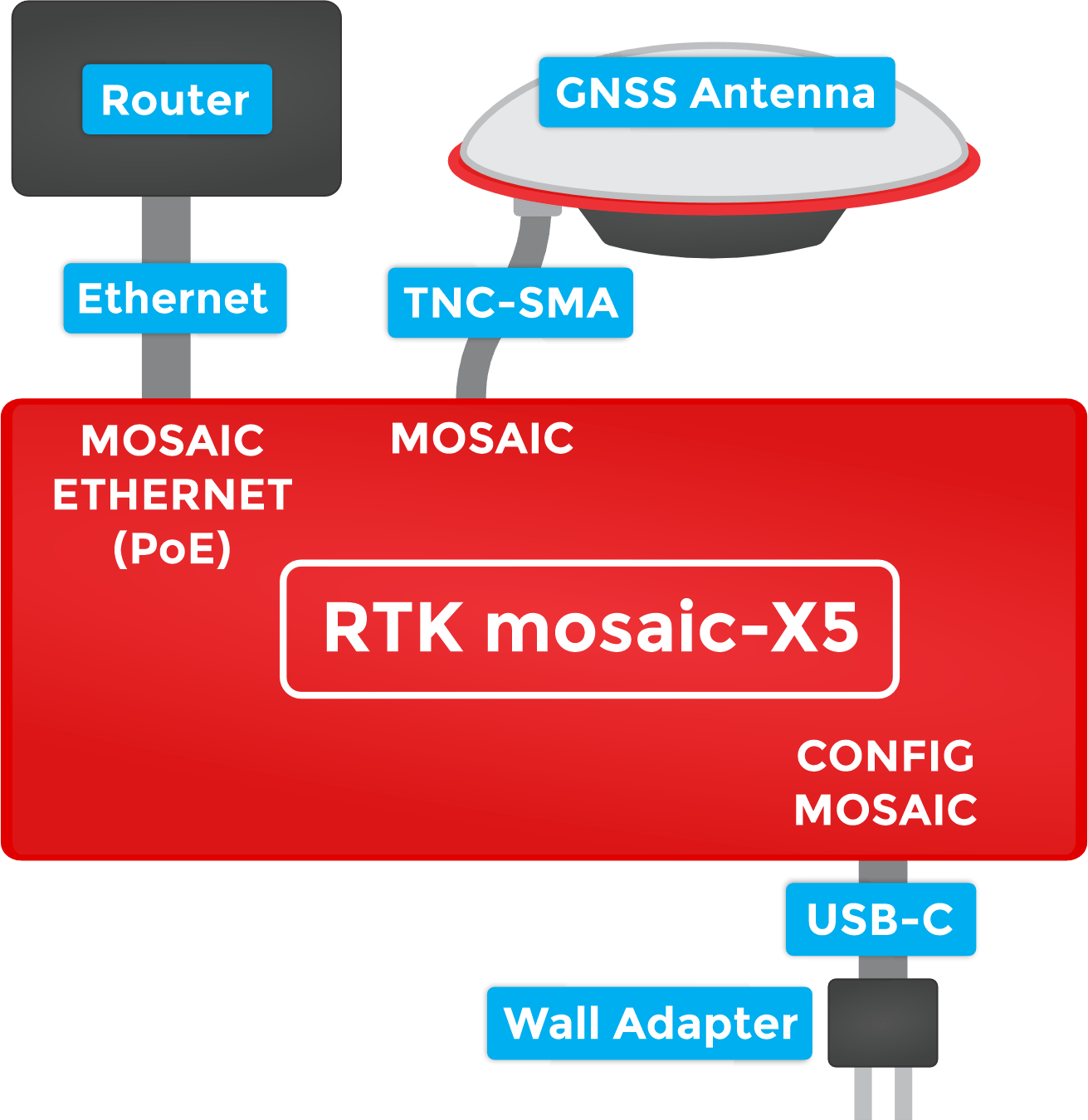
3- Link the Ethernet ports-
- Link the MOSAIC ETHERNET (PoE) and ESP32 ETHERNET ports using the supplied cable.
- The Ethernet ports support Auto-MDIX. You can use a standard Ethernet patch cable to link the ports. You do not need a crossover cable.
4- Connect to the CONFIG ESP32 USB port-
- To change the ESP32 firmware mode, you need to connect a computer to the CONFIG ESP32 USB-C port and use a Serial Terminal to change the mode.
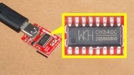
- You may need to install a driver, first, so that the CH340 serial interface chip is recognized. Please click the bar below for more details.
WiFi Mode (PNG) for the RTK mosaic-X5. Install CH340 Driver
Users may need to install the appropriate USB driver for their computer to recognize the serial-to-UART chip on their board/adapter. Most of the latest operating systems will recognize the CH340C chip on the board and automatically install the required driver. To manually install the CH340 driver on their computer, users can download it from the WCH website.
Download the latest CH340 USB driver from WCH Need Directions?
For more information, check out our video and hookup guide:
-
How to Install CH340 Drivers
5- Open a Serial Terminal-
- If you are using Windows, we still recommend the Tera Term serial terminal but there are plenty of alternatives. Please see our Serial Terminal Basics tutorial for more details.
- Open the connection to the CH340 using 115200 baud
6- Put the ESP32 firmware into WiFi mode-
- When you have the Serial Terminal open, you should see the
RTK_X5>console prompt. If you do not, hit Enter on your keyboard. If needed, click the RESET button on the front of the RTK mosaic-X5 to restart the ESP32 firmware.
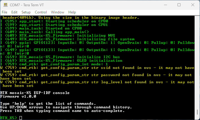
Console Prompt (PNG) for changing the RTK mosaic-X5 firmware mode. -
Type
helpand hit enter to see the help.
Console Help (PNG) for changing the RTK mosaic-X5 firmware mode. -
Type
showto see the current configuration.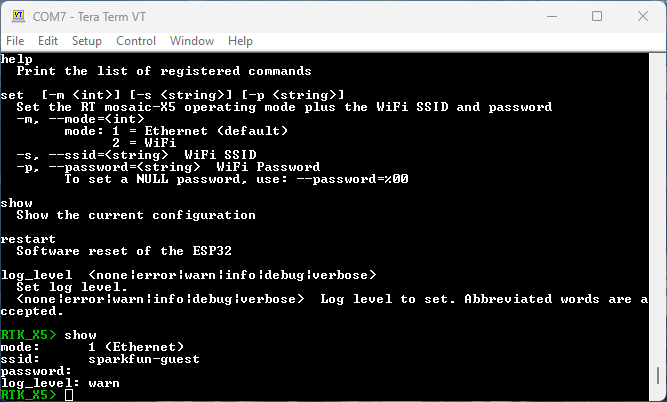
Console Show (PNG) for changing the RTK mosaic-X5 firmware mode. -
By default the firmware will be in Mode:
1(Ethernet). To change the mode to Mode:2(WiFi), we type: -
To set the WiFi SSID, type one of:
-
Likewise, to set the WiFi password, type one of:
-
To save time, you can set all three together with one of:
-
-
Finally, type
restartto restart the firmware with the new settings:
- When you have the Serial Terminal open, you should see the
Once the mosaic-X5 has acquired a satellite signal and is connected to the WiFi network, the OLED will display: the antenna's position as Latitude (Lat), Longitude (Long) and Altitude (Alt); the WiFi IP (Internet Protocol) network address.
When powering the RTK mosaic-X5 on for the first time, you may see the firmware restart (reboot) several times while it waits for the mosaic-X5 to initialize. This is not an error or anything to be concerned about.
Connect your computer, tablet or phone to the same network, open a web browser and navigate to the IP address shown on the OLED display. You should see the mosaic-X5's internal web page. The web page displays a lot of helpful information and can also be used to fully configure the mosaic-X5.
The firmware mode, SSID and password are stored in flash (non-volatile) memory. After changing them, you can disconnect the computer and power the RTK mosaic-X5 using the supplied wall adapter.
Not working?
The following sections will help if your RTK mosaic-X5 is not working as expected:
Using mosaic-X5 firmware >= 4.15.1?
With mosaic-X5 firmware 4.15.1, a user-defined username and password are mandatory on all IP interfaces. These must be entered as described in the Log-in procedure on all IP interfaces individually and separately. The ESP32 is connected via COM. It does not need to know the username and password unless you also change default access level for the COM ports. If you do, you need to ensure the RTK mosaic-X5 ESP32 firmware has been upgraded to version >= 1.0.5 and that the username and password have been set using set -u and set -x
No power?
The red power (PWR) LED will light up when the RTK mosaic-X5 has power. If the PWR LED is off, make sure the wall adapter has power and the USB cable is connected.
No position information?
The OLED display will only show position information (Lat, Long, Alt etc.) once a satellite signal has been acquired. If you see only the IP address on the display, check the SMA to TNC cable is connected correctly and that the antenna is outside with a clear view of the sky. Use a male-female SMA extension cable if needed to increase the cable length.
No IP address?
The mosaic-X5 Ethernet port is configured for Dynamic Host Configuration Protocol (DHCP). It expects the WiFi network to provide it with an IP address. If the IP address is all zeros (0.0.0.0), check that your router has DHCP enabled. Most do.
Subnet 3 is reserved for the mosaic-X5's USB-C connection (Ethernet-over-USB). If your router / switch is allocating addresses using subnet 3 (192.168.3.***), please change its settings so it uses a different subnet.
No web page?
If you can not see the mosaic-X5's internal web page, please check that your computer / tablet / phone is connected to the same network. If you are using a phone, check it is connected to the router WiFi - and not using its mobile data connection.
Subnet 3 is reserved for the mosaic-X5's USB-C connection (Ethernet-over-USB). If your router / switch is allocating addresses using subnet 3 (192.168.3.***), please change its settings so it uses a different subnet. If it is using subnet 3, both the mosaic-X5 and your device will appear to have valid IP addresses but will not be able to communicate.
Wrong mode?
If you still can not see the mosaic-X5's internal web page, please check that the ESP32 firmware is in the correct mode. Press the RESET button to restart the ESP32 and watch the text, which scrolls up the OLED display. You should see Mode 2: WiFi displayed briefly. If you see Mode 1: Ethernet, the firmware is in the wrong mode. Follow the instructions above to change the mode to 2 (WiFi).
The mosaic-X5 has a built-in high-speed USB port which supports Ethernet-over-USB. To take advantage of this interface, you first need to install the Septentrio drivers.
1- Connect the GNSS antenna-
- Inside your RTK mosaic-X5 kit, you will find the L1/L2/L5 GNSS "UFO" antenna. It has a TNC connection. Use the supplied TNC-SMA cable to connect the antenna to the mosaic-X5 MOSAIC SMA connection.
- The antenna needs a clear view of the sky. If you are working indoors, put the antenna outside and pass the cable through a window. (Insulating double-glazed windows have a coating which can block the GNSS signal. For best results, put the antenna outside.)
- If you are going to use your RTK mosaic-X5 as an RTK Base, the antenna needs to be securely mounted to a structure so that it cannot be moved and has a clear view of the sky. Any movement in the antenna will cause inaccurate readings by RTK rovers. Please see the Required Materials for links to our GNSS Antenna Mounting Hardware Kit and GNSS Magnetic Antenna Mount - 5/8" 11-TPI
2- Download and install Septentrio RxTools-
- The Septentrio mosaic-X5 Resources page has download links for the mosaic-X5 datasheet, firmware, firmware guide, hardware manual, how-to videos and the RxTools support tool suite.
- RxTools includes the driver for the USB-C port plus several tools, which you can use to control and configure the mosaic-X5, forward data, log data, analyze the log files, convert the log files to other formats, and configure the module for use with other GIS software.
- Download and install RxTools.
3- Connect the RTK mosaic-X5 to your computer-
- Use the supplied USB-C cable to connect the CONFIG MOSAIC port to your computer.
4- Open the X5 web page-
- Open a web browser on your computer and navigate to 192.168.3.1 to view the mosaic-X5's internal web page.
You can now use the RxTools suite to take full advantage of the sophisticated mosaic-X5.
Not working?
The following sections will help if your RTK mosaic-X5 is not working as expected:
Using mosaic-X5 firmware >= 4.15.1?
With mosaic-X5 firmware 4.15.1, a user-defined username and password are mandatory on all IP interfaces. These must be entered as described in the Log-in procedure on all IP interfaces individually and separately. The ESP32 is connected via COM. It does not need to know the username and password unless you also change default access level for the COM ports. If you do, you need to ensure the RTK mosaic-X5 ESP32 firmware has been upgraded to version >= 1.0.5 and that the username and password have been set using set -u and set -x
No power?
The red power (PWR) LED will light up when the RTK mosaic-X5 has power. If the PWR LED is off, make sure the USB cable is connected.
No position information?
The OLED display will only show position information (Lat, Long, Alt etc.) once a satellite signal has been acquired. If you see only an IP address on the display, check the SMA to TNC cable is connected correctly and that the antenna is outside with a clear view of the sky. Use a male-female SMA extension cable if needed to increase the cable length.
No web page?
If you can not see the mosaic-X5's internal web page at 192.168.3.1, please check that your computer / tablet / phone is connected correctly to the USB-C port.
Subnet 3 is reserved for the mosaic-X5's USB-C connection (Ethernet-over-USB). If your computer is simultaneously connected to an Ethernet or WiFi network that also uses subnet 3 (192.168.3.***), please change the network settings so it uses a different subnet.
Firmware mode
You can have the mosaic-X5 connected to your computer via USB-C, while it is also simultaneously connected via Ethernet (firmware mode 1) or WiFi (firmware mode 2). If you connect the mosaic-X5 Ethernet port directly to your network or router, ensure the firmware is in mode 1. If you have the mosaic and ESP32 Ethernet ports linked for WiFi mode, ensure the firmware is in mode 2.
Hardware Overview
Read Before Handling PCB!
ESD Sensitivity
The mosaic-X5 module is sensitive to ESD. Use a proper grounding system to make sure that the working surface and the components are at the same electric potential.
ESD Precaution
As recommended by the manufacturer, we highly encourage users to take the necessary precautions to avoid damaging their module.
- The RTK mosaic-X5 features ESD protection on the USB-C connectors and ethernet jacks.
- The mosaic-X5 module features internal ESD protection to the
ANT_1antenna input.
-

iFixit Anti-Static Wrist Strap
TOL-25572
ESP32 Firmware
We have intentionally kept the ESP32 firmware as simple as possible - supporting only two modes: Ethernet (Mode: 1) and WiFi (Mode: 2). The intention is that you can easily develop your own firmware for the RTK mosaic-X5 using the Espressif ESP IDF if the SparkFun firmware does not meet your needs.
You can of course modify the hardware too, should you want to. The design is completely open-source.
Limitations
The ESP32 firmware we provide is only compatible with basic SSID and Password WiFi authentication. The firmware is not compatible with networks that implement other provisioning methods such as a captive portal, a QR code, or Wi-Fi protected setup.
Hardware Overview
In this section, we walk you through the hardware design, interfaces, I/O connections, power options and more.
Info
The RTK mosaic-X5 is inspired by the Septentrio mowi (mosaic wireless) open-source design. The SparkFun design builds upon mowi, adding: separate Ethernet ports with mag jacks and Power-over-Ethernet; robust I/O headers with screw cage connections and configurable I/O voltage (3.3V or 5V); µSD data storage; and an OLED display.
Schematic
Users can download the full schematic for the RTK mosaic-X5 in *.pdf format.
Dimensions
Details about the aluminum enclosure can be found on the Metal Enclosure - Custom Aluminum Extrusion (6in. x 4in. PCB) product page.
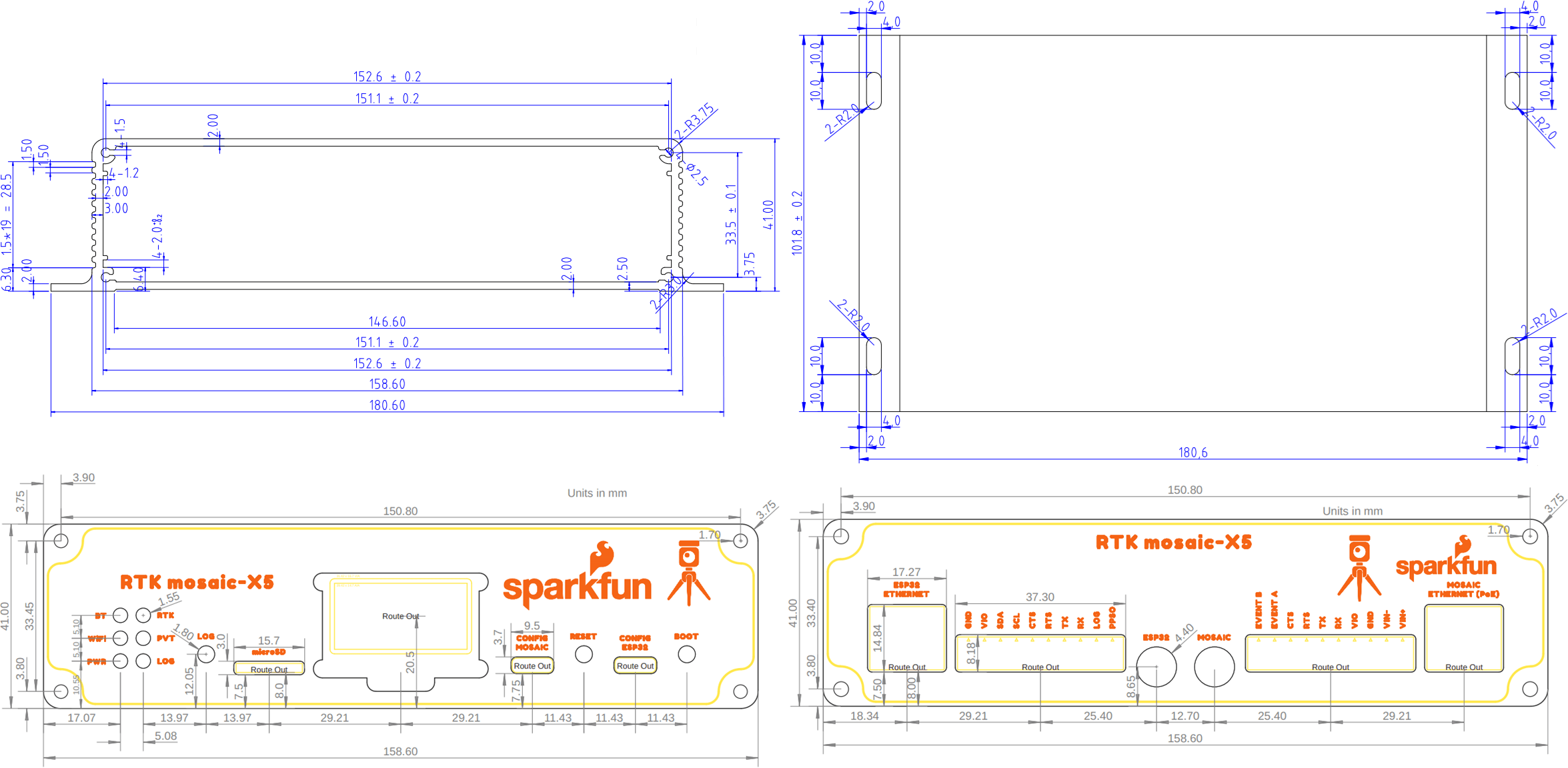
The circuit board dimensions are illustrated in the drawing below; the listed measurements are in inches.
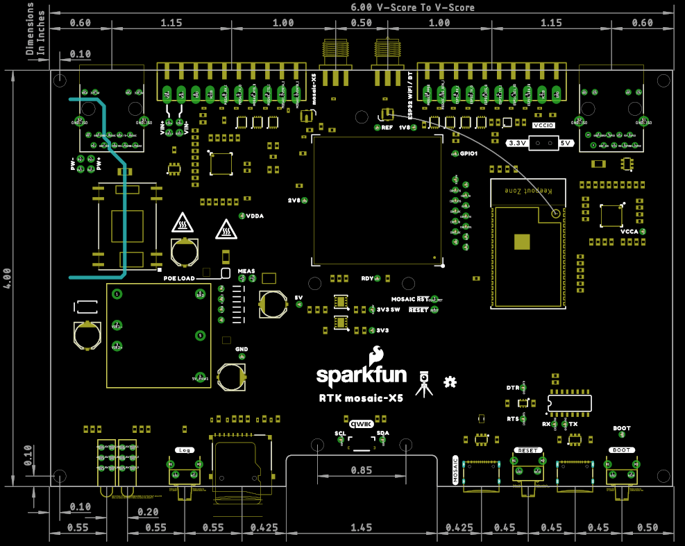
Need more measurements?
For more information about the board's dimensions, users can download the Eagle files for the board. These files can be opened in Eagle and additional measurements can be made with the dimensions tool.
Eagle - Free Download!
Eagle is a CAD program for electronics that is free to use for hobbyists and students. However, it does require an account registration to utilize the software.
 Dimensions Tool
This video from Autodesk demonstrates how to utilize the dimensions tool in Eagle, to include additional measurements:
The dimensions and technical specifications of the GNSS antenna can be found on the GNSS Multi-Band L1/L2/L5 Surveying Antenna - TNC (SPK6618H) product page.
Source: SPK6618H Datasheet (PDF)
Power Options
The mosaic-X5 and the ESP32 both required 3.3V power. To simplify the power circuitry, the four power sources are combined into a common 5V rail which then feeds individual 3.3V 1A regulators for the mosaic-X5 and the ESP32.
Power connections on the RTK mosaic-X5 PCB.
The RTK mosaic-X5 can be powered individually or in combination, with any of the following:
USB Ports- 5V; delivered via theMOSAIC CONFIGand/orESP32 CONFIGUSB-C connectors.Power-over-Ethernet- Range: 36 to 57V; delivered via theMOSAIC ETHERNETRJ45 MagJack connector.External DC Power- Range: 9 to 36V; delivered via theVIN+andVIN-screw cage terminals.
Measure Current Draw
If you want to measure the board's current draw, you can open the MEAS jumper and measure the current via a pair of breakout pads (see the Jumpers section).
Protection Components
Diodes are used to combine and protect the power sources from each other. Also, a 2A resettable fuse (green) provides additional protection.
Info
For more details, users can reference the schematic and the datasheets of the individual components on the board.
The mosaic-X5 and ESP32 both have USB-C connections. These USB ports can be used to power the RTK mosaic-X5 during the initial configuration when the mosaic-X5 or ESP32 are connected to a computer.
CH340 Driver
The CH340 allows the ESP32-WROVER to communicate with a computer/host device through the USB-C connection. This allows the ESP32 to show up as a device on the serial (or COM) port of the computer. Users will need to install the latest drivers for the computer to recognize the CH340 (see USB Driver section).
The mosaic-X5 Ethernet port supports Power-over-Ethernet (PoE), allowing the RTK mosaic-X5 to be powered by the network. This is very useful when the RTK mosaic-X5 is mounted remotely - perhaps in a weatherproof box up on the roof. Data and power can be delivered through a single cable, avoiding the need for a separate power connection.

The RTK mosaic-X5 includes a fully-isolated DC-DC converter, for applications where you may want to power the unit from a vehicle. The DC-DC converter accepts DC voltages between 9V and 36V, regulating this down to 5V. The converter is fully isolated to 1.5kV and operates with ~90% efficiency.
VIN+ and VIN- screw terminal pins for the external DC power input.

Vehicle Power
For 12V or 24V vehicle power:
- Connect 12V or 24V to the
VIN+screw cage terminal - Connect 0V (chassis) to the
VIN-screw cage terminal
Power Source
Additionally, make sure that the power source from the vehicle is not directly tied to the vehicle's battery, Always On, or accessory circuits. Otherwise, users will risk killing the battery while the engine is off.
We recommend locating the ignition on or switched power circuit, which is only powered when the key is in the On position and the engine is running.
Note
The On position, is where a key normally rests after the engine is started. However, users can still move the key from the Off position and into the On position without starting the engine. In this case, the alternator is not running and keeping the battery charged.
Modern eco-efficient vehicles may automatically shut down the engine if the vehicle is idling too long. Therefore, cutting off the vehicle's alternator that keeps the battery charged. Luckily, most vehicles with this automatic start/stop technology will monitor the battery's voltage and restart the engine when required. With this in mind, users may want to initially monitor their battery voltage, in case their vehicle isn't "so smart"  .
.
Ground Loop
If desired, users can link VIN- to the adjacent GND screw cage terminal. However, this will bypass the voltage isolation and could introduce an unwanted ground loop, particularly if the GNSS antenna ground (shield, 0V) is also connected to the chassis.
mosaic-X5
The heart of our product is of course the mosaic-X5 GNSS module from Septentrio. It is a very sophisticated chip with multiple interfaces: UARTS, USB and Ethernet. The COM2 and COM3 UART pins, plus GPIO1 and GPIO2, are available as 0.1" test points should you need access to them.
The Septentrio mosaic-X5 GNSS module.
ESP32-WROVER
The only interface the mosaic-X5 doesn't offer is WiFi and that's why we've included an Espressif ESP32-WROVER processor (16MB flash, 8MB PSRAM) with its own Ethernet connection. You can connect the mosaic-X5 directly to your Ethernet network - our product supports Power-over-Ethernet too. Or you can link the mosaic-X5 Ethernet port to the ESP32 Ethernet port and have the ESP32 provide WiFi connectivity. In that mode, the ESP32 becomes an Ethernet to WiFi Bridge, seamlessly passing WiFi traffic to and from the mosaic-X5 via Ethernet.
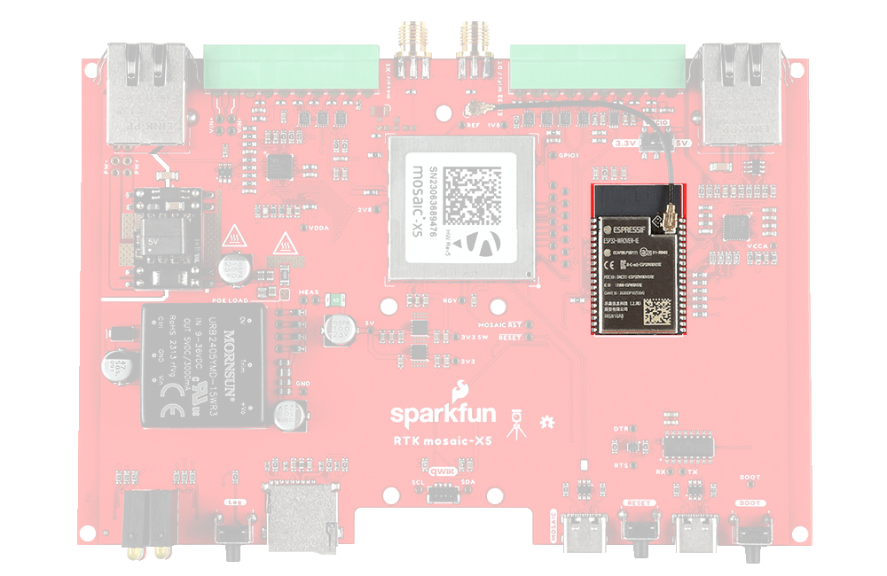
The Espressif ESP32-WROVER processor.
Think of the ESP32 as a co-processor, or riding shotgun... The mosaic-X5 COM4 UART is linked to the ESP32, allowing the two to communicate directly without needing the Ethernet link. In our firmware, the ESP32 requests NMEA GGA data over this link and then displays it on the I2C OLED display.
WiFi Network Compatibility
The ESP32 is only compatible with 2.4GHz bands and cannot access the 5GHz band.
ESP32 Firmware
We have intentionally kept the ESP32 firmware as simple as possible - supporting only two modes: Ethernet (Mode: 1) and WiFi (Mode: 2). The intention is that users can easily develop their, own firmware for the RTK mosaic-X5 using the Espressif ESP IDF if the SparkFun firmware does not meet their needs.
Provisioning Limitations
- The ESP32 firmware we provide is only compatible with basic
SSIDandPasswordWiFi authentication. - The firmware is not compatible with networks that implement other provisioning methods such as a captive portal, a QR code, or Wi-Fi protected setup.
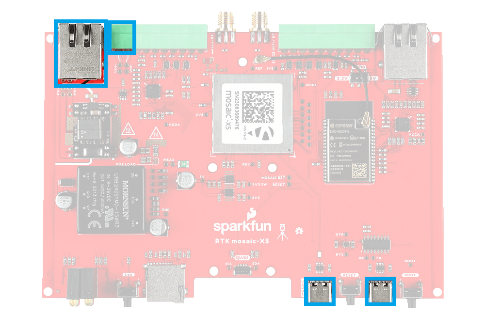
Ethernet PHY Interfaces
The mosaic-X5 and ESP32 have identical KSZ8041NLI Ethernet PHY interfaces, both connected using Reduced Media-Independent Interfaces (RMII). These allow the mosaic-X5 and ESP32 to be linked directly to your Ethernet network or router, or to each other when the ESP32 is acting as an Ethernet-to-WiFi Bridge.

Ethernet connections: ESP32 (left) and mosaic-X5 (right).

The two Ethernet physical layer interfaces and connections.
USB-C Connectors
The mosaic-X5 and ESP32 both have USB-C connections. The MOSAIC USB port is high-speed and connected to the X5 through a balancing transformer. The ESP32 USB port is connected through a CH340 USB-UART IC.
USB-C connections: mosaic-X5 (left) and ESP32 (right).
The USB-C data connections on the RTK mosaic-X5 PCB.
Info
The RTK mosaic-X5 can draw power from either or both USB ports, in addition to Power-over-Ethernet and the DC-DC external input described above.
CH340 Driver
The CH340 allows the ESP32-WROVER to communicate with a computer/host device through the USB-C connection. This allows the ESP32 to show up as a device on the serial (or COM) port of the computer. Users will need to install the latest drivers for the computer to recognize the CH340 (see USB Driver section).
µSD Socket
The µSD socket is connected directly to the mosaic-X5 via a one-bit SDIO interface for fast data logging. The mosaic-X5 supports µSD cards with a FAT32 file system (i.e. only cards up to 32GB in size).
µSD slot and LOG button.
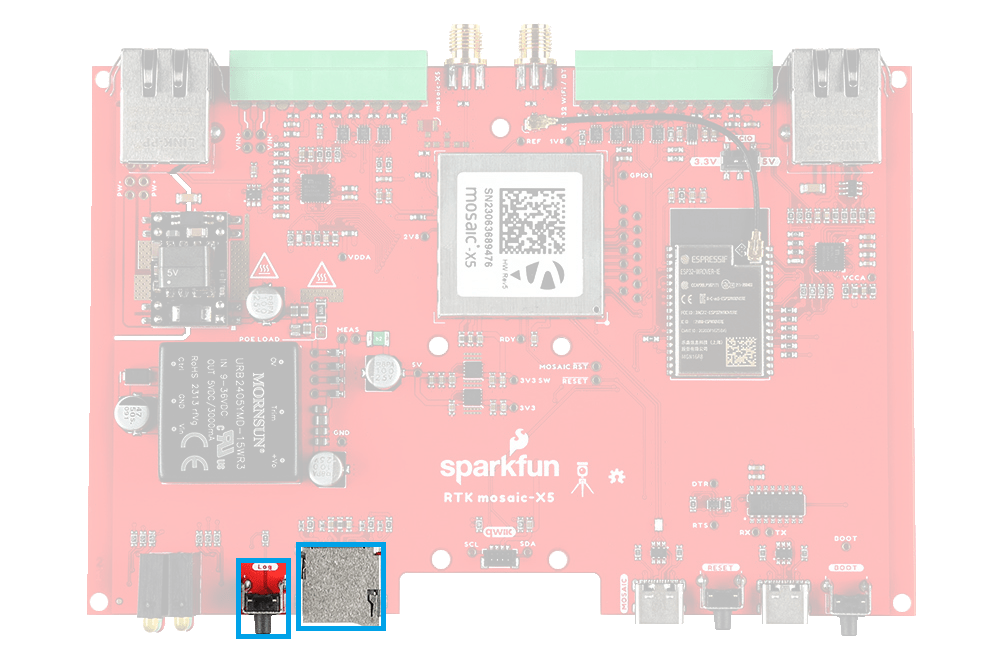
µSD socket and Log button on the RTK mosaic-X5 PCB.
Operation Instructions
Initial Configuration
Before logging can take place, it is necessary to define a "logging stream" using the Logging page or RxTools. Streams can contain NMEA or SBF (Septentrio Binary Format) data; SBF can contain RTCM and/or RINEX.

Instructional Video
How to log data to the SD card of the Septentrio mosaic receiver module
Once the stream is defined, users can control the data logging operation through the LOG button.
- A short press of the LOG button (< 5s) toggles data logging to the SD card on and off.
- The red
LOGLED will flash while logging is taking place.
- The red
- A long press, holding the LOG button for more than 5 seconds (> 5s) and then releasing it, will force the board to:
- Unmount the SD card if it was mounted
- Mount the SD card if it was unmounted
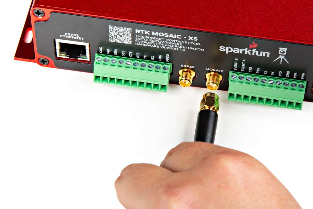
SMA Connectors
The RTK mosaic-X5 has robust SMA connectors for the mosaic-X5 GNSS antenna and the ESP32 WiFi / BT antenna.

The SMA connector for the GNSS antenna.

The connection for the GNSS antenna to the mosaic-X5.
The mosaic-X5 SMA connector is standard polarity and provides 5V power for an active antenna.

The RP-SMA connector for the WiFi/BLE antenna.
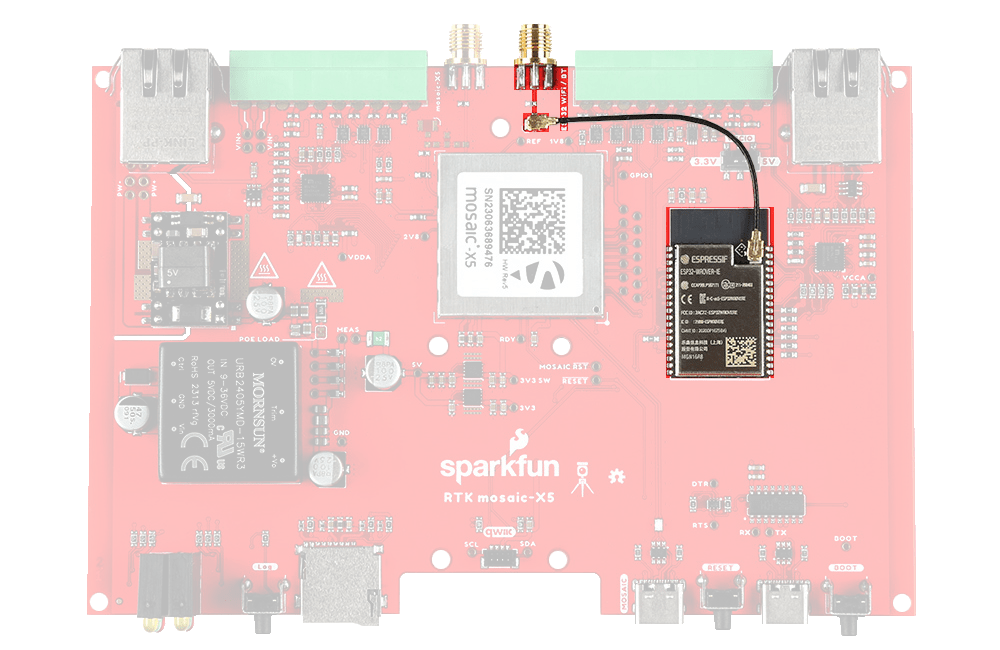
The connection for the WiFi / BLE antenna to the ESP32.
The ESP32 WiFi / BT SMA connector is reverse-polarity (RP). A short u.FL cable connects the SMA connector to the ESP32-WROVER itself.
Connector Polarity
When selecting antennas and/or cables for the RTK mosaic-X5, double-check the polarity for the connections.
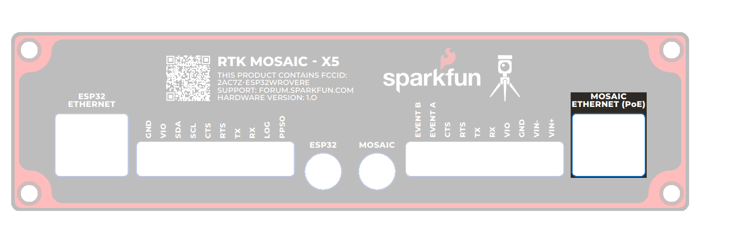
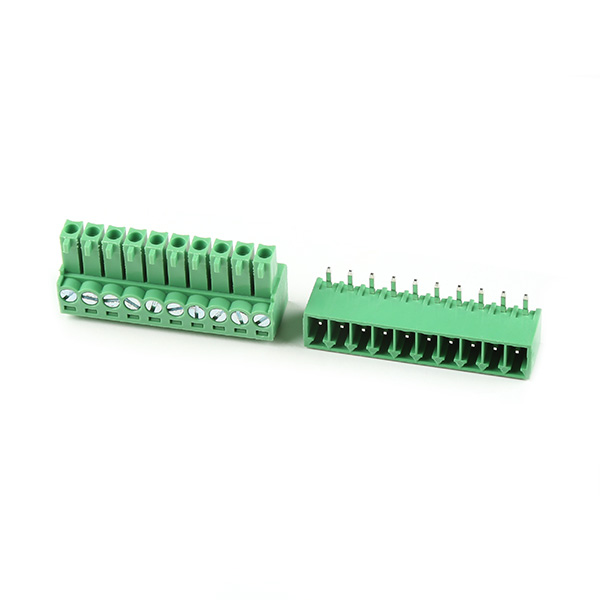
I/O Terminals
The RTK moasic-X5 is equipped with two 10-way 3.5mm screw cage terminal connectors.

I/O Screw Terminal Connections.

I/O Screw Terminal Connections on the RTK mosaic-X5 PCB.
These terminals are described in the tabs below. For more information on the I/O terminals, you can refer to the schematic.
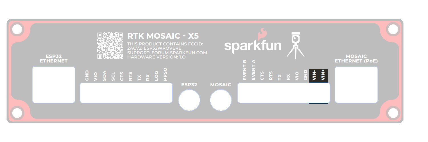
The VIN+ and VIN- terminals allow the RTK mosaic-X5 to be powered by an external DC power source - typically a 12V / 24V vehicle battery.
| Terminal | Function |
|---|---|
| VIN+ | External voltage: Min: 9V; Max: 36V |
| VIN- | Ground / Chassis / 0V |
Info
The DC-DC converter in the RTK mosaic-X5 provides 1.5kV isolation between VIN+/VIN- and 5V/GND. There is no direct electrical connection between VIN- and GND.
Ground Loop
If desired, users can link VIN- to the adjacent GND screw cage terminal. However, this will bypass the voltage isolation and could introduce an unwanted ground loop, particularly if the GNSS antenna ground (shield, 0V) is also connected to the chassis.
The I/O terminal voltage can be set to 3.3V or 5V via the small internal slide switch highlighted below:
The VIO terminals can be used as power outputs or logic-high references. Likewise, the GND terminals can be used for power return or as logic-low references.
| Terminal | Function |
|---|---|
| VIO | 3.3V or 5V power output or logic-high reference |
| GND | Ground / 0V or logic-low reference |
Info
The default position of the VIO switch is 3.3V.
Tip
The VIO and GND pins could be used to power (e.g.) a LoRa module. We recommend limiting the current draw from VIO to 200mA and never drawing more than 500mA peak. The upstream 3.3V regulator is rated at 1A but it also provides power for the ESP32 processor.
The mosaic-X5 UART COM1 connections are adjacent to the EVENTA and EVENTB terminals and are connected as follows:
| Terminal | Function | Notes |
|---|---|---|
| RX | COM1 UART Receive - Input | |
| TX | COM1 UART Transmit - Output | |
| RTS | COM1 UART Request To Send - Output | The module drives this pin low when ready to receive data |
| CTS | COM1 UART Clear To Send - Input | Must be driven low when ready to receive data from the module |
Tip
The COM1 I/O voltage is set by the I/O voltage selection switch.
Tip
The CTS input floats low. Pull CTS up to VIO to disable UART Transmit.
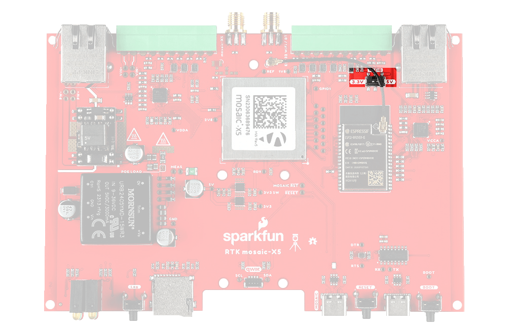
The mosaic-X5 EVENTA and EVENTB inputs can be used to mark or timestamp external events:
| Terminal | Function |
|---|---|
| EVENTA | Event A : Input |
| EVENTB | Event B : Input |
Tip
The EVENT voltage level is set by the I/O voltage selection switch.
Tip
The EVENT inputs are pulled low internally. Pull up to VIO to trigger an event.
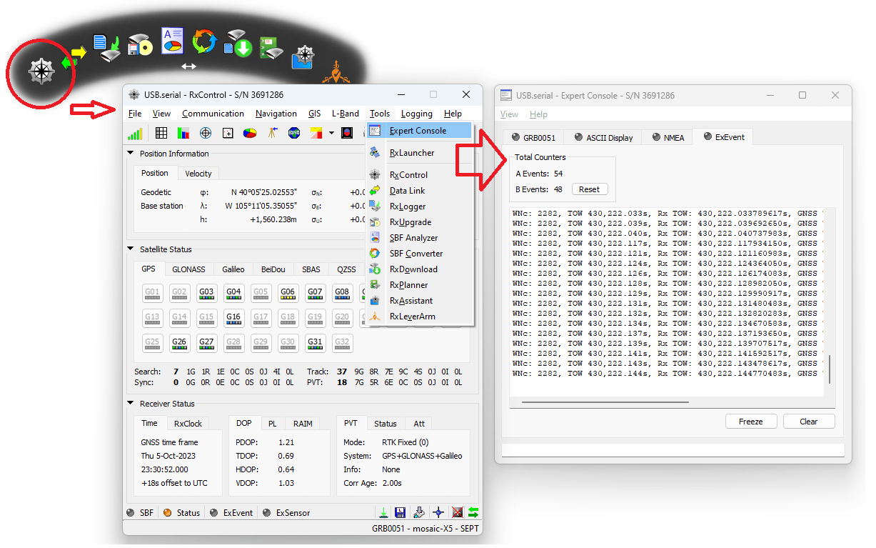
Tip
An easy way to observe the events is with RxTools RxControl Expert Console (under Tools) ExEvent tab:
The mosaic-X5 PPSO is a configurable Pulse-Per-Second output. By default, PPSO is high for 5ms at 1Hz. The polarity, frequency and pulse width can be adjusted with the setPPSParameters command.
| Terminal | Function |
|---|---|
| PPSO | Pulse-Per-Second : Output |
Tip
The PPSO voltage is set by the I/O voltage selection switch.
The mosaic-X5 LOG input starts and stops µSD logging. It is also used to mount and dismount the µSD card.
| Terminal | Function |
|---|---|
| LOG | Log : Input |
Tip
The LOG voltage level is set by the I/O voltage selection switch.
Tip
The LOG input is pulled up to VIO internally. Pull low to GND to start or stop logging.
Tip
Internal resistors allow the LOG I/O terminal and Log button to be used simultaneously. It is OK to press the Log button while the LOG terminal is being driven high (VIO).
Four ESP32 GPIO pins are connected to I/O screw terminals as follows. These pins are not used by version 1.0.0 of the RTK mosaic-X5 ESP32 firmware. They are available for you to use if you are developing your own firmware.
| Terminal | Suggested Function | Notes |
|---|---|---|
| RX | UART Receive | Input - connected to GPIO pin 34 through a level-shifter |
| TX | UART Transmit | Output - connected to GPIO pin 32 through a level-shifter |
| RTS | UART Request To Send | Output - connected to GPIO pin 33 through a level-shifter |
| CTS | UART Clear To Send | Input - connected to GPIO pin 35 through a level-shifter |
Tip
The I/O voltage is set by the I/O voltage selection switch.
Info
These pins are not used by version 1.0.0 of the ESP32 firmware.
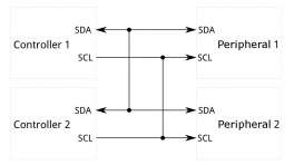
The ESP32 I2C (Wire) bus SDA and SCL signals are available via the I/O terminals. Internally, the I2C bus is used to configure the Qwiic OLED display. If you connect a logic analyzer to the SDA and SCL I/O terminals, you will be able to see the OLED traffic (address 0x3D). We made the SDA and SCL signals accessible in case you are developing your own firmware for the RTK mosaic-X5. The I/O terminals are fully level-shifted. It is OK to have a 5V I2C peripheral connected while also using the internal 3.3V Qwiic bus for the OLED.
| Terminal | Function |
|---|---|
| SDA | I2C Data |
| SCL | I2C Clock |
Tip
The I/O voltage is set by the I/O voltage selection switch.
What is Qwiic?
![]()
![]()
The Qwiic connect system is a solderless, polarized connection system that allows users to seamlessly daisy chain I2C boards together. Play the video below to learn more about the Qwiic connect system or click on the banner above to learn more about Qwiic products.
Features of the Qwiic System


Qwiic cables (4-pin JST) plug easily from development boards to sensors, shields, accessory boards and more, making easy work of setting up a new prototype.


There's no need to worry about accidentally swapping the SDA and SCL wires on your breadboard. The Qwiic connector is polarized so you know you’ll have it wired correctly every time, right from the start.
The PCB connector is part number SM04B-SRSS (Datasheet) or equivalent. The mating connector used on cables is part number SHR04V-S-B or an equivalent (1mm pitch, 4-pin JST connector).


It’s time to leverage the power of the I2C bus! Most Qwiic boards will have two or more connectors on them, allowing multiple devices to be connected.
Status LEDs
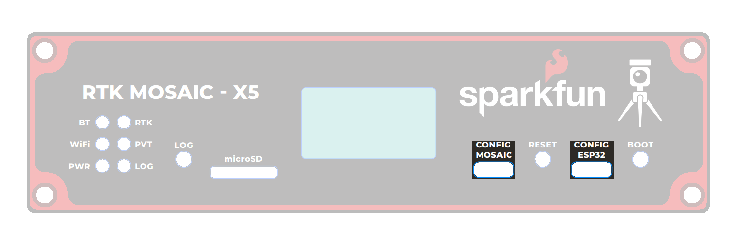
There are six status LEDs on the RTK mosaic-X5:
PWR- Power (Red)- Illuminates when power is applied
LOG- µSD Logging (Red)- Solid Red - µSD card is mounted
- Blinking Red - Data is being logged
- Off - µSD is dismounted or not present
WiFi- WiFi (Green)- The ESP32 firmware is using WiFi
- Connected to ESP32 GPIO pin 12
PVT- Position Velocity Time (Green)- Solid Green - The mosaic-X5 has valid Position, Velocity and Time
- Off - Satellite signal not present or acquired
BT- Bluetooth (Yellow)- The ESP32 firmware is using BT
- Connected to ESP32 GPIO pin 13
- Not used by firmware v1.0.0
RTK- Real-Time Kinematic (Yellow)- Solid Yellow - The mosaic-X5 has an RTK Fixed solution
- Blinking Yellow - The mosaic-X5 has an RTK Float solution
- Off - No RTK solution
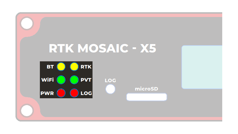
The status indicator LEDs on the RTK mosaic-X5.

The status indicator LEDs on the RTK mosaic-X5 PCB.
OLED Display
The RTK mosaic-X5 has a 128x64 pixel OLED display, controlled by the ESP32 via I2C. After some initial diagnostic messages, the display will show position, time and other data from the mosaic-X5 NMEA GGA message, plus the Ethernet / WiFi IP address.
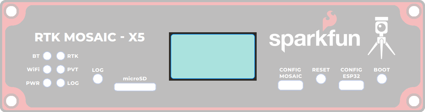
The OLED display on the RTK mosaic-X5.
- Time: - Universal Time Coordinate (UTC) in
HHMMSS.SSformat- Note: the display is updated approximately every 2 seconds. The time shown may not be precise.
- Lat: - Latitude in
DDMM.MMMMMMMN/Sformat (this is the format used by the GGA message) - Long: - Longitude in
DDDMM.MMMMMMME/Wformat (this is the format used by the GGA message) - Fix: - the GNSS fix type
- Sat: - the number of satellites used in the navigation solution
- Note: this is not the same as "Satellites In View"
- HDOP: - Horizontal Dilution Of Precision
- Note: this is a dimensionless number indicating the horizontal position accuracy
- Alt: - the Altitude in meters
- Note: this is the altitude above Mean Sea Level, not Geoid
- IP: - the mosaic-X5 IP address, obtained via Ethernet or WiFi
- The X5's internal configuration page can be viewed at this address
Example Data
Below, is an example data set recorded on the RTK mosaic-X5 at SparkFun HQ; where the antenna was located on the roof of the building. The antenna was above the loading dock, just about where it is displayed on the map. The table, below, is an example of how to convert the information on the display into the time and coordinate values.

| Data | Format | Value | |
|---|---|---|---|
| Time | 191525.90 |
HHMMSS.SS |
7:15:25.90 PM (UTC) 12:15:25.90 PM (MST) |
| Latitude | 4005.4192485 N |
DDMM.MMMMMMM N/S |
40° 5.4162485' N 40° 5' 24.97491" N 40.090270808° N |
| Longitude | 10511.0873663 W |
DDDMM.MMMMMMM E/W |
105° 11.0873663' W 105° 11' 5.241978" W 105.184789438° W |
Buttons
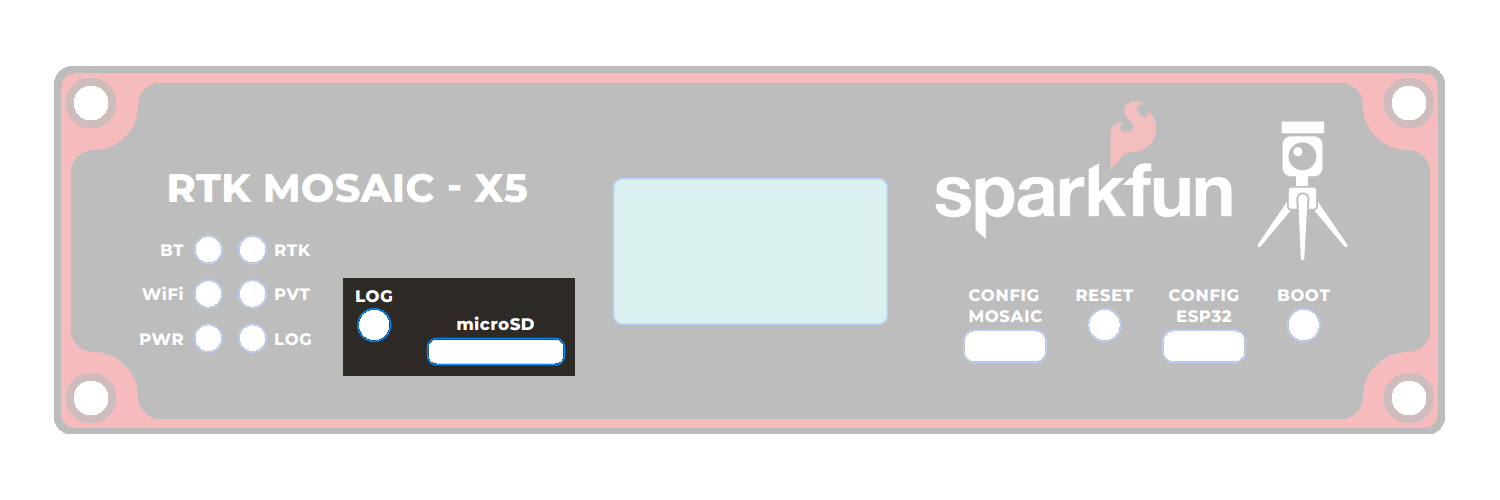
There are three buttons on the RTK mosaic-X5: RESET, BOOT, and LOG.

Buttons on the RTK mosaic-X5.

Buttons on the RTK mosaic-X5 PCB.
Once a logging stream is defined, users can control the data logging operation through the LOG button.
- A short press of the LOG button (< 5s) toggles data logging to the SD card on and off.
- The red
LOGLED will flash while logging is taking place.
- The red
- Holding the LOG button for more than 5 seconds (> 5s) and then releasing it, will force the board to:
- Unmount the SD card if it was mounted
- Mount the SD card if it was unmounted
Instructional Video
How to log data to the SD card of the Septentrio mosaic receiver module
The RESET button allows users to reset the firmware running on the ESP32-WROVER module without disconnecting the power.
The BOOT button can be used to force the ESP32 into the serial bootloader. Holding down the BOOT button, while connecting the RTK mosaic-X5 to a computer through its USB-C connector or resetting the board will cause it to enter the Firmware Download mode. The ESP32 will remain in this mode until it power cycles (happens automatically after uploading new firmware) or the RESET button is pressed.
- Hold the BOOT button down.
- Reset the MCU.
- While unpowered, connect the board to a computer through the USB-C connection.
- While powered, press the RESET button.
- Release the BOOT button.
- After programming is completed, reboot the MCU.
- Press the RESET button.
- Power cycle the board.
BOOT and GPIO0
The ESP32 GPIO pin 0 is connected to the BOOT button. But is also used by the firmware to generate the 50MHz clock for the RMII Ethernet PHY interface.
Pressing the BOOT button while the firmware is running in mode 2 (WiFi) will interrupt the clock and cause Ethernet communication with the mosaic-X5 to fail.
Jumpers
Never modified a jumper before?
Check out our Jumper Pads and PCB Traces tutorial for a quick introduction!
-
How to Work with Jumper Pads and PCB Traces
There are several jumpers on the RTK moasic-X5 PCB which can be used to (e.g.) disable the LEDs or allow measurement of the board's current draw.

The jumpers on the top of the RTK mosaic-X5 PCB.

The jumpers on the bottom of the RTK mosaic-X5 PCB.
- POE LOAD - This jumper can be used to disconnect the Power-over-Ethernet (PoE) module 50Ω load.
- The PoE module has a minimum load of 100mA. We included the 50Ω load to ensure this is met. If you can ensure this by other means, open this jumper to disconnect the load.
- LED Jumpers
- LINK (x2) - open these jumpers to disable the Ethernet Link LEDs.
- SPEED (x2) - open these jumpers to disable the Ethernet Speed LEDs.
- RTK - open this jumper to disable the mosaic-X5 Real-Time Kinetic LED.
- PVT - open this jumper to disable the mosaic-X5 Position Velocity Time LED.
- LOG - open this jumper to disable the mosaic-X5 Log LED.
- BT - open this jumper to disable the ESP32 BT LED.
- WiFi - open this jumper to disable the ESP32 WiFi LED.
- PWR - open this jumper to disable the Power LED.
- Button Jumpers
- BOOT - open this jumper to disconnect the ESP32 BOOT pushbutton.
- RESET - open this jumper to disconnect the ESP32 RESET pushbutton.
- SHLD (x2) - open these jumpers to isolate the USB-C connector shield from GND.
- I2C - open this dual jumper to disconnect the pull-ups for the SDA and SCL I/O terminals.
- Note: the internal 3.3V Qwiic bus has its own pull-ups which are disconnected by default. These can be enabled by closing the dual jumper under the OLED Qwiic connector. We suggest you only do this if you are disconnecting the OLED.
- VIN+ and VIN-
- Open these jumpers if you wish to isolate (disconnect) the external DC power terminals. The breakout pads can then be used to feed in power from an alternate source.
- PW+ and PW-
- Open these jumpers if you wish to isolate (disconnect) the Power-over-Ethernet pins on the MOSAIC Ethernet magjack. The breakout pads can then be used to feed in power from an alternate source.
- MEAS
- Open the MEAS jumper if you wish to measure the total current drawn by the RTK mosaic-X5, or (e.g.) wish to add an ON/OFF switch. The breakout pads can then be used to attach a multimeter or a mechanical power switch.
- MEAS is upstream of the two 3.3V regulators and downstream of the four power source combination and protection diodes.
Hardware Assembly
Warning
When assembling the RTK mosaic-X5, users should attach any power connections last. While there shouldn't be any issues with hot-swapping peripherals, it is common practice to power electronics as the last step of the assembly process (and the power should be disconnected before removing components).
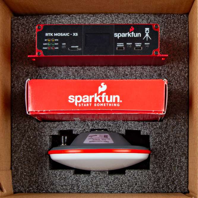
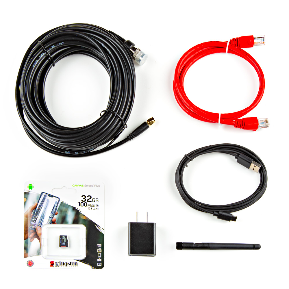
What is in the Box?
The RTK mosaic-X5 comes packaged as a complete kit, with all the accessories you'd need to set up an RTK base station.
Inside the box, users will find the GNSS antenna, RTK mosaic-X5 in its aluminum enclosure, and another box containing additional accessories. Inside, the accessory box, users will find the CAT-6 Ethernet cable, USB cable, SMA to TNC cable, USB power supply, WiFi antenna, and 32GB SD card.
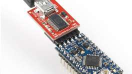
USB-C Ports
The USB ports are utilized to configure the mosaic-X5 module and ESP32 WiFi settings. Additionally, the USB ports can also be used as a power source for the RTK mosaic-X5.
The USB port to the mosaic-X5 can be used to configure the module through an IP port, for serial communication to stream the GNSS data, and access the SD card as a mass storage device. To connect to the mosaic-X5, users only need to plug a USB-C cable into the CONFIG MOSAIC USB port and their computer.

The RTK mosaic-X5 with USB-C cable being attached.
With the default firmware, the USB port for the ESP32 is used for serial communication to configure the network settings of the Ethernet-to-WiFi bridge. To configure the network settings for the ESP32, users only need to plug a USB-C cable into the CONFIG ESP32 USB port and their computer.

The RTK mosaic-X5 with USB-C cable being attached.
Software Requirements
Depending on their computer's operating system, users may need to install USB drivers to interface with the mosaic-X5 and/or the ESP32. Users may also need to install a terminal emulator for serial communication with the mosaic-X5 and the ESP32.
Antennas
In order to receive GNSS signals, users will need a compatible antenna. With the parts included in this kit, connect the L1/L2/L5 (tri-band) GNSS antenna to the RTK mosaic-X5 using the TNC-to-SMA cable.

Attaching a tri-band GPS antenna to the TNC-SMA cable.
Attaching a TNC-SMA cable to the SMA connector on the RTK mosaic-X5.
For the WiFi connection, users will need a compatible antenna. Connect the WiFi antenna, included in this kit, to the RTK mosaic-X5.

Attaching a 2.4GHz WiFi antenna to the RP-SMA connector on the RTK mosaic-X5.
WiFi Network Compatibility
The ESP32 is only compatible with 2.4GHz bands and cannot access the 5GHz band.
The ESP32 firmware we provide is only compatible with basic SSID and Password WiFi authentication.
- The firmware is not compatible with networks that implement other provisioning methods such as a captive portal, a QR code, or Wi-Fi protected setup.
Mounting Location
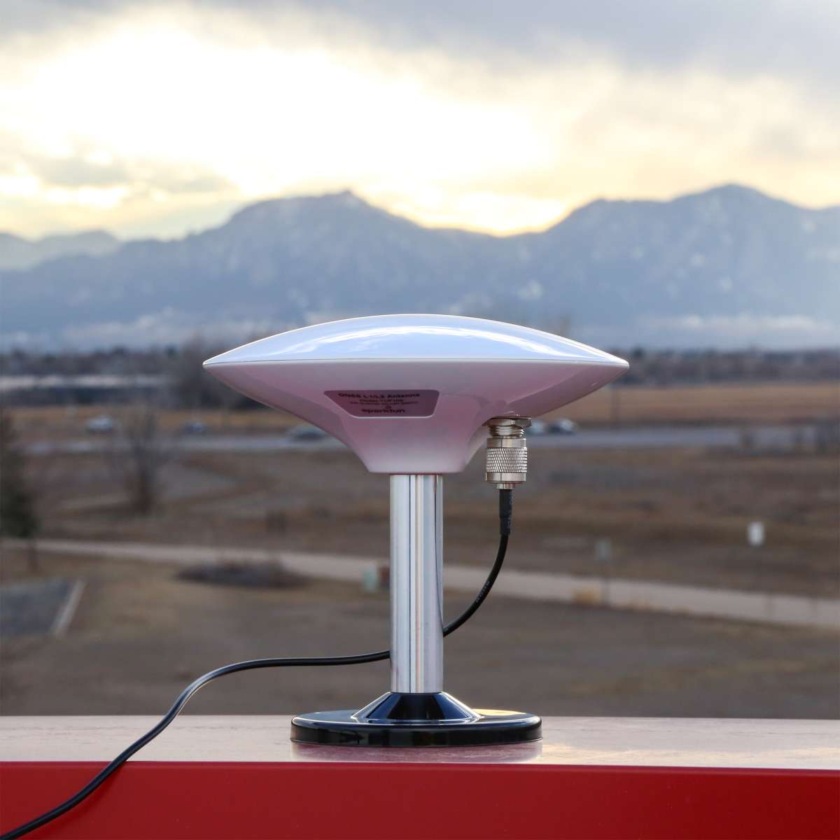
Users should mount their GNSS antenna outside, where it will have a clear, unobstructed view of the sky. Avoid areas with nearby buildings, EMF structures (i.e. radio towers or power lines), and vegetation (i.e. trees). These objects can increase errors due to signal muti-path, interference, and elevated noise plane.

Connector Polarity
When selecting antennas and/or cables for the RTK mosaic-X5, double-check the polarity of the connection.
Ethernet Jacks
There are two ethernet jacks on the RTK mosaic-X5, which can be used to provide network access to the mosaic-X5 module. In addition, one of the ethernet jacks supports power over ethernet (PoE) to power the device.
The jack to the mosaic-X5 allows users to provide internet access and power; it supports PoE. To provide network access, users should connect the RTK mosaic-X5 from the MOSAIC ETHERNET (PoE) jack to their local network with the (CAT-6) ethernet cable provided in the kit.
- To power the device, a PoE network switch or PoE injector should be installed in between the network connection to the RTK mosaic-X5.

MOSAIC ETHERNET (PoE) jack.
The jack to the ESP32 allows users to provide WiFi access to the mosaic-X5, by utilizing the ESP32 as a WiFi network bridge.
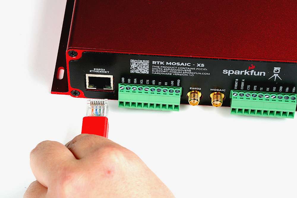
ESP32 ETHERNET jack.
To set up the WiFi bridge, connect the provided (CAT-6) ethernet cable between the MOSAIC ETHERNET (PoE) and ESP32 ETHERNET jacks on the RTK mosaic-X5.
MOSAIC ETHERNET (PoE) and ESP32 ETHERNET jacks.
Configure WiFi Connection
Users will need to configure the WiFi connection for the ESP32, through the CONFIG ESP32 USB-C port.
Cable Management
Users should avoid wrapping the ethernet cable around the WiFi antenna; doing so will result in the loss of data packets and cause the web page to freeze. If users must coil the wiring, we recommend that the coil be placed at least 2-3" away from the WiFi antenna.
Configuration: mosaic-X5 Settings
Users can configure the mosaic-X5 module through the network connection (i.e. ethernet or WiFi).
SD Card Slot
An µSD card slot is available for users to log and store data, locally on the board. Users will need to insert a compatible SD card and configure the mosaic-X5 module for data logging.
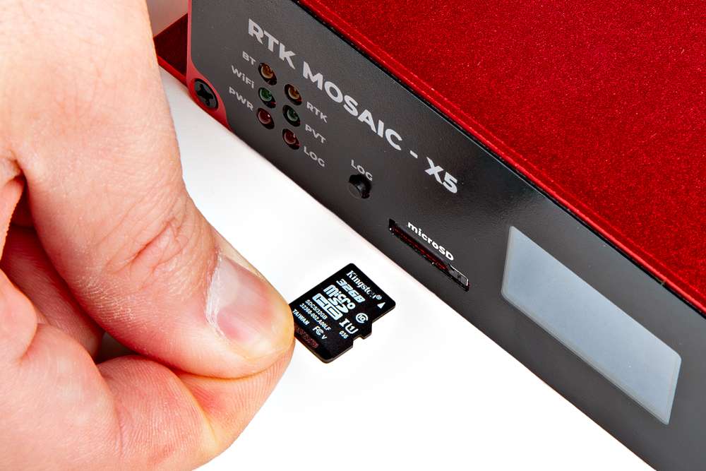
Inserting an SD card into the RTK mosaic-X5.
SD Card Compatibility
The mosaic-X5 supports µSD cards with a FAT32 file system (i.e. only cards up to 32GB in size).
Initial Configuration
Before logging can take place, it is necessary to define a "logging stream" using the Logging page or RxTools. Streams can contain NMEA or SBF (Septentrio Binary Format) data; SBF can contain RTCM and/or RINEX.
Instructional Video
How to log data to the SD card of the Septentrio mosaic receiver module
Button Operation
There are multiple ways to configure and enable data logging to an SD card. However, the simplest method is with the LOG button. Once the stream is defined,
- Pressing the LOG button (< 5s) toggles data logging to the SD card on and off.
- Holding the LOG button for more than 5 seconds (> 5s) and then releasing it, will force the board to:
- Unmount the SD card if it was mounted
- Mount the SD card if it was unmounted
For more information, please reference the SD Card Slot section.
IO Terminals
Users can easily attach accessories to the RTK mosaic-X5 by wiring them into the terminal blocks on the back of the enclosure.
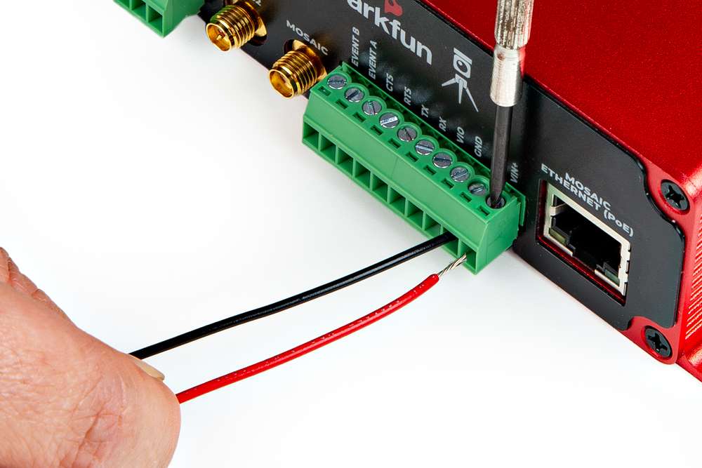
Connecting a wire to the terminal block.
Multiple Connections
For multiple connections or wiring harnesses, users can disconnect the terminal blocks from their sockets on the RTK mosaic-X5.
Users can wiggle or use a soft/rigid object to carefully pry the terminal block off from its connector. In the picture below, a plastic name tag (~1.5mm thick) is used to carefully pry the terminal block up. We have also found the edge of a PCB ruler works great too.
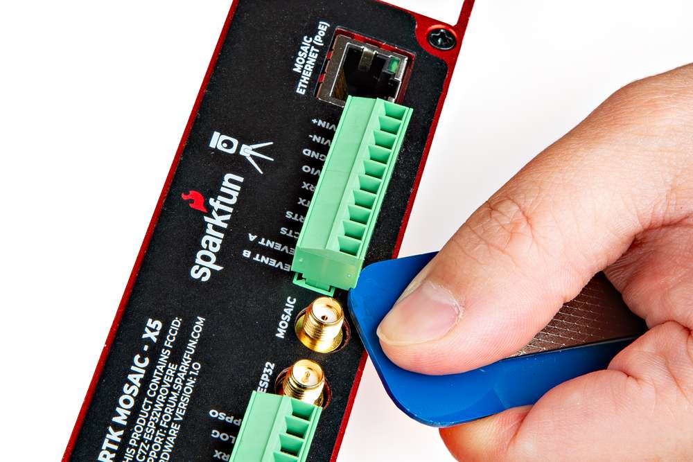
Once wired up, users can simply push the terminal block back into its socket.


Warning
To avoid shorts or damaging the RTK mosaic-X5, verify the wiring with the labels on the back of the enclosure.
Connecting a Radio
Radio Transceivers
Users can also utilize the terminal blocks to interface with one of our radio transceivers for RTK correction data. We recommend utilizing our breadboard cable to connect those radios to the RTK mosaic-X5.
-
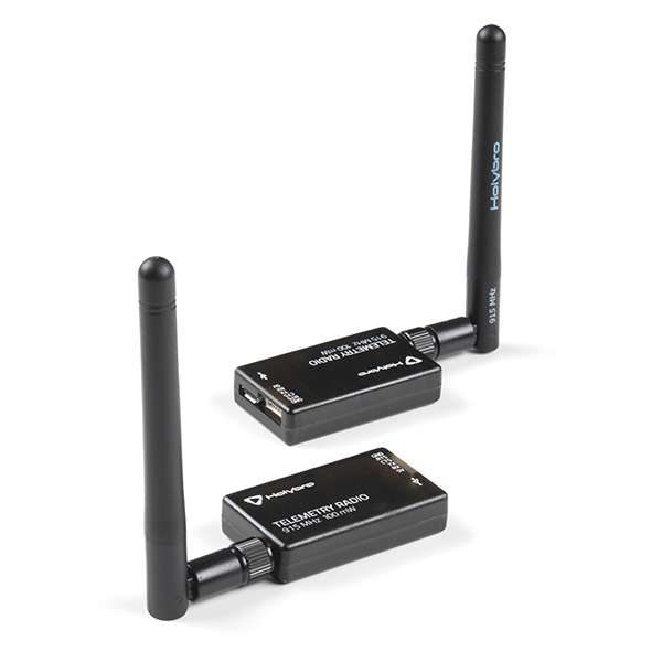
SiK Telemetry Radio V3 - 915MHz, 100mW
WRL-19032 -
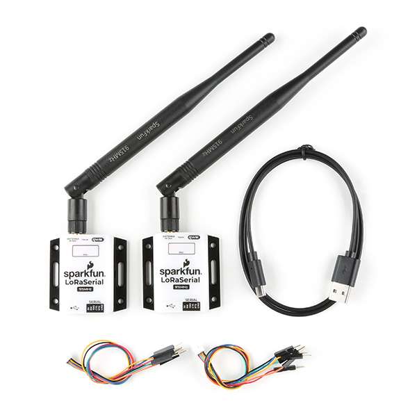
SparkFun LoRaSerial Kit - 915MHz (Enclosed)
WRL-20029 -
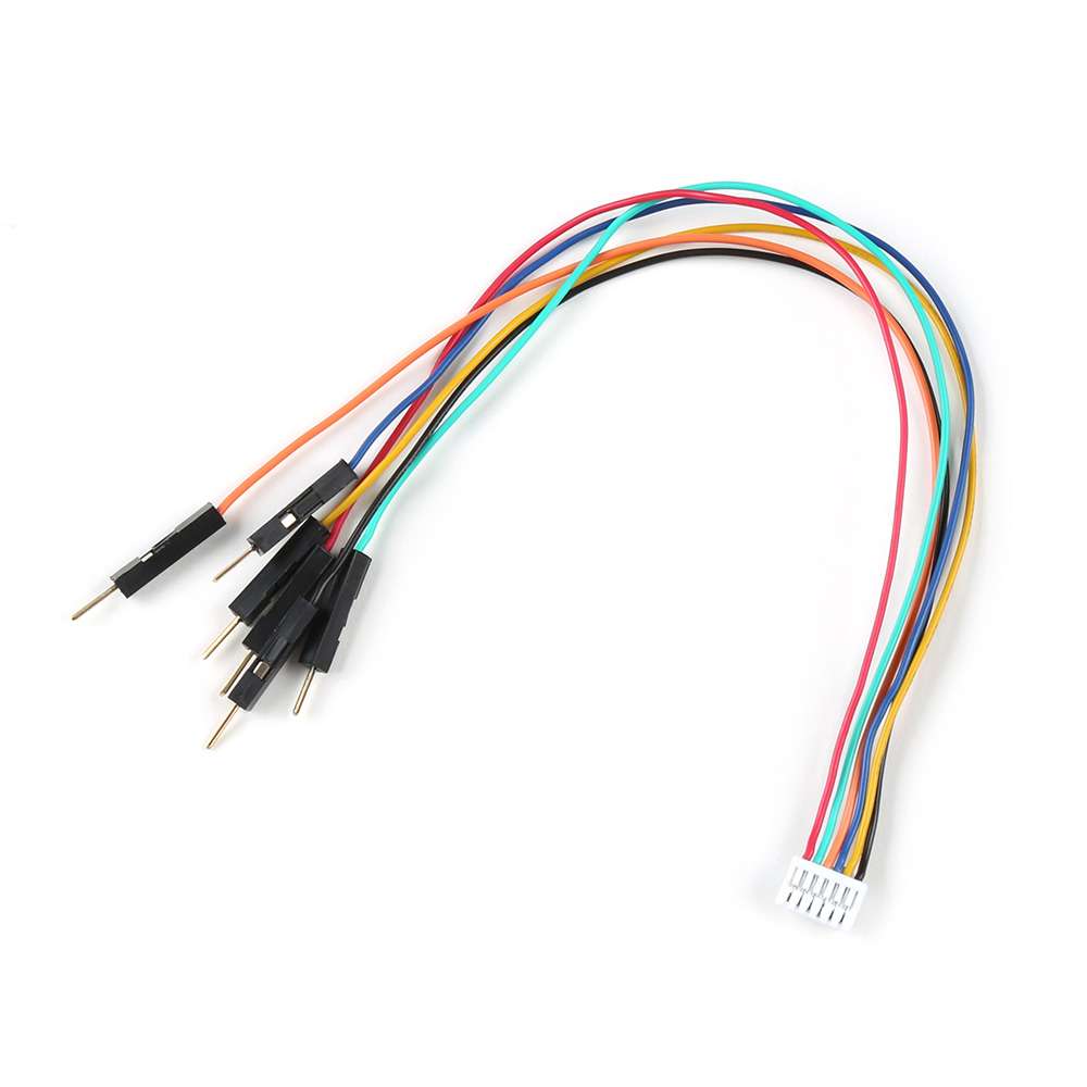
Breadboard to JST-GHR-06V Cable - 6-Pin x 1.25mm Pitch (For LoRaSerial)
CAB-23353
Wiring the Connections
When connecting the RTK mosaic-X5 to one of our radio transceivers, users need to be aware of the pin connections between the products. Although the labels on each device may vary, their pins will function the same (except for the power input/output pins).
Warning
Please remember that the power output (VIO) is preset to 3.3V by default. When utilizing the SiK telemetry radios, users will need to open the enclosure and move the VIO switch.
Below is a diagram of the pin connections for the 6-pin JST GH connector on the radios, which should be also labeled on their enclosure.
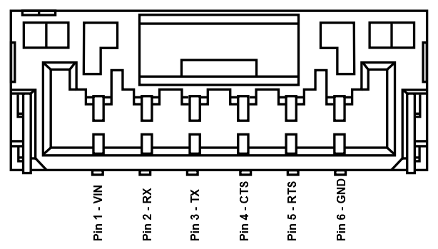
| Label | 5V |
RX/RXI |
TX/TXO |
CTS |
RTS |
GND |
|---|---|---|---|---|---|---|
| Function | Voltage Input - SiK: 5V - LoRaSerial: 3.3 to 5V |
UART - Receive | UART - Transmit | Flow Control Clear-to-Send |
Flow Control Ready-to-Send |
Ground |
Below are the UART pin connections to the mosaic-X5 GNSS receiver, which are labeled for the terminal blocks on the RTK mosaic-X5 enclosure.
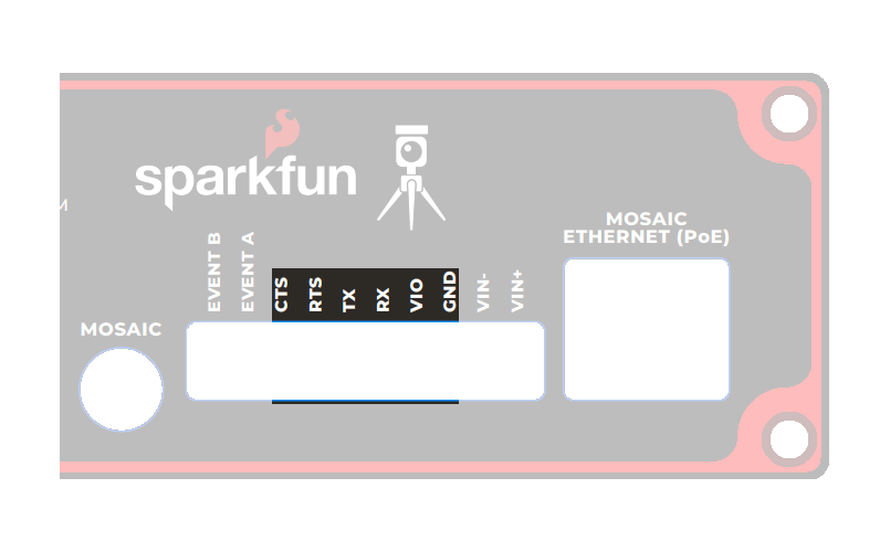
| Label | VIO |
RX |
TX |
CTS |
RTS |
GND |
|---|---|---|---|---|---|---|
| Function | Voltage Output - 5V or 3.3V (see switch) |
UART - Receive | UART - Transmit | Flow Control Clear-to-Send |
Flow Control Ready-to-Send |
Ground |
When connecting the RTK mosaic-X5 to either of the radios, the wiring connections should follow the table below. If the flow control is not enabled, then only the RX, TX, and GND pins are utilized. As an example, the wiring between a host system (i.e. RTK mosaic-X5) and the LoRaSerial Kit radio is shown in the image below; as documented in the LoRaSerial product manual.
| RTK mosaic-X5 | RX | TX | RTS | CTS | GND |
|---|---|---|---|---|---|
| Radio | TX | RX | CTS | RTS | GND |
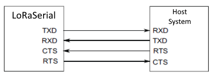
Source: LoRaSerial product manual
Pairing Radios
By default, the radios in the LoRaSerial Kit - 915MHz are pre-configured for point-to-point communication and a paired with each other. For instructions on other configurations, please reference the product manual for the LoRaSerial Kit.
Software Overview
ESP32 Firmware
We have intentionally kept the ESP32 firmware as simple as possible - supporting only two modes: Ethernet (mode 1) and WiFi (mode 2). The intention is that you can easily develop your own firmware for the RTK mosaic-X5 using the Espressif ESP IDF if the SparkFun firmware does not meet your needs.
You can of course modify the hardware too, should you want to. The design is completely open-source.
Limitations
The ESP32 firmware we provide is only compatible with basic SSID and Password WiFi authentication. The firmware is not compatible with networks that implement other provisioning methods such as a QR code or a captive portal.
Note
The mosaic-X5 module has numerous capabilities and a multitude of ways to configure and interface with them. Without regurgitating all the information that is documented in Septentrio's user manuals and videos, we have tried to highlight a good majority of the module's aspects.
With that said, please feel free to file an issue if you feel we have missed something that may benefit other users. (Don't forget to provide us with a link to the documentation and what section the information is located.)
mosaic-X5
RxTools Software Suite
Tip
Even if you aren't necessarily interested in it, we highly recommend that users install the RXTools software suite before plugging in their board. For Windows PCs, it also includes the USB driver for the module that enables the Ethernet-over-USB support and virtual COM ports.
Users should install the RXTools software suite on their computer to interact with the mosaic-X5 module through the USB interface. The software package includes the USB-IP driver1 necessary to recognize the board as an ethernet device on Windows PCs (1).
- On Linux, the standard Linux CDC-ACM driver is suitable.
System Requirements2
- Windows 7
- Windows 8
- Windows 10
- Fedora 23 (or later) using Qt technology.
- The standalone tools (except
bin2asc) will run on older distributions.
- The standalone tools (except
The minimal hardware requirements (1Hz update3):
- CPU: 1 GHz processor
- RAM: 1 GB RAM
- Screen Resolution: 1024×768 or higher resolution
Installation Instructions2
Users can install RxTools software suite by running the installation executable4(1), located in the RxTools\windows directory of the downloaded *.zip file5. During the installation process, users will be notified if a previous version of RxTools is already installed then the previous version will be uninstalled. Next, users will need to provide an installation directory for the RxTools software suite. Users will then select which of the following applications6 are installed:
- For RxTools v22.1.0, the installation filename is
RxTools_22_1_0_Installer.exefor Windows PCs.
- RxControl
- SBF Converter
- SBF Analyzer
- RxLogger
- RxUpgrade
- RxDownload
- RxPlanner
- Data Link
- RxAssistant
- RxLauncher
Warning
It is recommended that users NOT install RxControl as root, for security reasons and to avoid installation overwrites of other system settings. To make RxTools available to more than one user, provide a shared installation directory.
Users can install RxTools software suite by running the installation binary4(1), located in the RxTools/linux-i386/ directory of the downloaded *.zip file5. During the installation, users will be prompted for an installation directory. If there are any previous installations of RxControl, please use a different directory to avoid conflicts.
- For RxTools v22.1.0, the installation filename is
RxTools_22_1_0_Installer.binfor Linux.
Permission Settings
Once installed, users may need to reconfigure their permission settings:
-
RxTools will need rights to access the
/dev/ttyS*serial ports.-
To access the serial ports, users must be part of the
uucpandlockgroups (1). This can be configured by editing the/etc/group7 file and adding the username to the lines defining theuucpgroup and thelockgroup.For example, when adding the user
jsmithto theuucpgroup, users would modify the/etc/groupfile as shown below: -
On Linux machine administered centrally on a local network, ask your system administrator to be included in the
uucpandlockgroups.
-
-
RxTools also needs read/write (
rw) access(4) to the/dev/ttyS*serial ports.-
Users can change the permissions with the
chmod8 command:
-
- On most Linux operating systems, the
/dev/ttyS*devices are owned byrootand belong to theuucpgroup with read/write (rw) access. Additionally, the devices are normally locked by writing a file in the/var/lock/directory, with the same permissions. - Remove
- Replace with this line
- By default, users will normally have read/write (
rw) access to the/dev/ttyS*serial ports. - where users must specify the port number
e.g./dev/ttyS0might be portCOM1
Note
In order for these changes to take effect, users must update their environment by logging out and back in.
Be aware that the X-session has to be restarted as well. On most systems, this can be done by pressing the key combination Ctrl + Alt + Backspace
64-bit OS
In order to run the RxTools on a 64-bit Linux operating system, users might have to install the 32-bit version of the C standard library.
- For Fedora installations, this is the
glibc.i686package. - The equivalent for Debian(/Ubuntu) installations is the
ia32-libspackage.
USB Driver
If users haven't already installed the RxTools software suite on their Windows PC, they will need to install the USB driver1 necessary to recognize and interact with the mosaic-X5 module through the USB interface.
A Windows USB driver for the mosaic-X5 can be installed through two methods:
- RxTools Software Suite (1)
- mosaic-X5 GNSS Receiver Module (2)
- The driver is installed during the installation process.
- The installation file for the Windows USB driver will be available from the mass-storage device when the board is initially connected to the computer.
Once installed, the driver emulates two virtual serial ports, which can be accessed as standard COM ports to the receiver.
Terminal Emulators
Most terminal emulation programs will not make a distinction between virtual or native COM ports. However, for virtual serial ports, the port settings (i.e. baud rate, etc.) are not relevant and the default configuration is used in the terminal emulation program. However, the physical/native COM ports will have the following default setting:
- Baudrate: 115200bps
- Data Bits: 8
- Parity: No
- Stop Bits: 1
- Flow Control: None
Having Trouble?
For users who are having trouble installing the USB driver, we have an archived version (v3.0.29) of the installation file. Users can download version 3.0.2 of the driver, by clicking on the button below.
On Linux, the standard Linux CDC-ACM driver is suitable for the mosaic-X5 module.
Web Interface
With the USB driver installed, the mosaic-X5 module supports Ethernet-over-USB. The default IP address allocated for the Ethernet-over-USB interface is 192.168.3.1. This IP can be entered in any browser to open a connection to the receiver's Web Interface as shown below.
All the drop-down navigation tabs in the web interface.
Info
The default IP address cannot be changed; this feature is only to be used when a single receiver is connected to your computer.
Invalid IP Address (WiFi Only)
One of the documentation pages on Septentrio's website, specifies a default IP address of 192.168.20.1 for the web interface. However, that address is for a WiFi enabled product and cannot be used with this product.
ESP32
USB Driver
Users will need to install a USB driver for the CH340 serial-to-USB chip, in order to communicate with the ESP32 module. The latest USB drivers for the CH340 are available from the manufacturer, on the WCH website:
Need Directions?
For users having trouble installing the CH340 USB driver, check out our video and hookup guide:
-
How to Install CH340 Drivers
Terminal Emulator
In order to configure the WiFi settings on the ESP32, users will need to install a serial terminal emulator on their computer.
For Windows computers, we highly recommend TeraTerm.
Some Linux operating systems will already have the screen terminal emulator preinstalled.
Need Directions?
Check out our hookup guide to install your favorite terminal emulator:
-
Serial Terminal Basics
WiFi Credentials for the Network Bridge
With the CH340 USB driver and a terminal emulator installed, users will now be able to configure the WiFi credentials on the ESP32. In order for the firmware to operate properly, users should have their RTK mosaic-X5 assembled with the network bridge in WiFi Mode.
Need Directions?
For more information, check out our video and hookup guide:
1- Open a Serial Terminal- Open the connection to the CH340 using a baud rate of 115200bps
2 - Put the ESP32 firmware into WiFi mode
* Type **`show`** to see the current configuration.
<figure markdown>
[{ width="400" }](./assets/img/hookup_guide/Console_Show.png "Click to enlarge")
<figcaption markdown>[Console Show (PNG)](./assets/img/hookup_guide/Console_Show.png) for changing the RTK mosaic-X5 firmware mode.</figcaption>
</figure>
* By default the firmware will be in **Mode: `1`** (Ethernet). To change the mode to **Mode: `2`** (WiFi), we type:
!!! terminal
``` bash
set -m 2
```
!!! tip "Long Arguments"
The console supports both short and long args, so we could type:
``` bash
set --mode=2
```
* To set the WiFi SSID, type one of:
!!! terminal
``` bash
set -s YOUR_SSID
set --ssid=YOUR_SSID
```
* Likewise, to set the WiFi password, type one of:
!!! terminal
``` bash
set -p YOUR_PASSWORD
set --password=YOUR_PASSWORD
```
* To save time, you can set all three together with one of:
!!! terminal
``` bash
set -m 2 -s YOUR_SSID -p YOUR_PASSWORD
set --mode=2 --ssid=YOUR_SSID --password=YOUR_PASSWORD
```
* Finally, type **`restart`** to restart the firmware with the new settings:
!!! terminal
``` bash
restart
```
??? tip "NULL (empty) password"
To clear the password - making it NULL / empty - type one of:
!!! terminal
``` bash
set -p %00
set --password=%00
```
Once the mosaic-X5 has acquired a satellite signal and is connected to the WiFi network, the OLED will display: the antenna's position as Latitude (Lat), Longitude (Long) and Altitude (Alt); the WiFi IP (Internet Protocol) network address.
When powering the RTK mosaic-X5 on for the first time, you may see the firmware restart (reboot) several times while it waits for the mosaic-X5 to initialize. This is not an error or anything to be concerned about.
Connect your computer, tablet or phone to the same network, open a web browser and navigate to the IP address shown on the OLED display. You should see the mosaic-X5's internal web page. The web page displays a lot of helpful information and can also be used to fully configure the mosaic-X5.
The firmware mode, SSID and password are stored in flash (non-volatile) memory. After changing them, you can disconnect the computer and power the RTK mosaic-X5 using the supplied wall adapter.
WiFi Connections (PNG) for the RTK mosaic-X5.
Once the mosaic-X5 has acquired a satellite signal and is connected to the WiFi network, the OLED will display the antenna's position as Latitude (Lat), Longitude (Long) and Altitude (Alt); the WiFi IP (Internet Protocol) network address. The firmware mode, SSID and password are stored in flash (non-volatile) memory. After changing them, you can disconnect the computer and power the RTK mosaic-X5 using the supplied wall adapter.
The OLED display will only show position information (Lat, Long, Alt etc.) once a satellite signal has been acquired. If you see only the IP address on the display, check the SMA to TNC cable is connected correctly and that the antenna is outside with a clear view of the sky. Use a [male-female SMA extension cable](https://www.sparkfun.com/interface-cable-sma-female-to-sma-male-10m-rg58.html) if needed to increase the cable length.
No IP address?
The mosaic-X5 Ethernet port is configured for Dynamic Host Configuration Protocol (DHCP). It expects the WiFi network to provide it with an IP address. If the IP address is all zeros (0.0.0.0), check that your router has DHCP enabled. Most do.
Subnet 3 is reserved for the mosaic-X5's USB-C connection (Ethernet-over-USB). If your router / switch is allocating addresses using subnet 3 (192.168.3.***), please change its settings so it uses a different subnet.
Info
When powering the RTK mosaic-X5 on for the first time, you may see the firmware restart (reboot) several times while it waits for the mosaic-X5 to initialize. This is not an error or anything to be concerned about.
With the RTK mosaic-X5 operating with the configured WiFi network bridge, users should be able to open a web browser on any connected device and navigate to the IP address shown on the OLED display. The browser should be able to access the mosaic-X5's internal web page, where users can configure the mosaic-X5.
ESP32 Firmware - Update
The firmware running on the ESP32 is based heavily on the firmware for the Septentrio mowi. SparkFun added some bells and whistles, primarily to support the OLED display. The full firmware source code is available in the GitHub repo. It was developed and compiled with the Espressif ESP-IDF version 5.1.5.
The most recent version of the firmware is v1.0.5, released on April 22nd 2026. If you purchased your RTK mosaic-X5 before this date, you may enjoy the improvements in v1.0.5:
Changes added at v1.0.5:
- The firmware now supports a username and password for the X5 itself
- This is to support mosaic-X5 firmware versions >= 4.15.1 where a username and password are mandatory on IP interfaces (webUI, Ethernet-over-USB, CLI over TCP/IP)
- The username and password are not mandatory on COM and USB (virtual COM) ports, unless you set the
Default Access Level Per Interface(setDefaultAccessLevel/sdal) to none for COM and/or USB ports - The ESP32 firmware only needs to know the username and password if the default access levels have been changed
- For more information about the X5 Log-in procedure, please read this Septentrio documentation
- If you upgrade the X5 firmware to 4.15.1:
- Enter your user-defined username and password, using the Factory credentials RxAdmin and S3pt3ntr10, as described in the Log-in procedure
- You will need to enter the user-defined username and password whenever you connect over an IP interface
- Logging in via the ESP32 on a COM port does not remove the need to log in on IP interfaces. You still need to log in on each IP interface individually and separately
- Upgrade the ESP32 Firmware to v1.0.5, following the procedure described below
- If the ESP32 needs to know the username and password: in the ESP32 Serial Terminal / console, use option set -u to set the X5 username and option set -x to set the X5 password
- Turn the RTK mosaic-X5 off and back on again
Changes added at v1.0.4:
- The firmware now includes an efficient SBF and NMEA parser
- Previously the NMEA GPGGA and SBF IPStatus messages were polled, this resulted in the OLED being updated once every ~2 seconds
- In v1.0.4: NMEA Stream10 carries the GPGGA message at 1Hz; SBF Stream10 carries the IPStatus message OnChange
- The OLED is now updated on the arrival of the GPGGA message, at exactly 1Hz
- The firmware now ensures that the SBF and NMEA protocols are enabled for output on X5 COM4
- Previously, the firmware would stall if either SBF or NMEA were disabled
- The firmware now supports the NMEA GN Talker ID, in addition to GP
- Previously setting the Talker ID to GN would cause the firmware to stall
- The OLED now displays the Latitude and Longitude in DD MM SS.SSSS format, to match the format of the X5's internal web page
- Previously the format was DDMM.MMMMMM, copied directly from the GPGGA message
- The firmware will perform a soft reset of the GNSS during startup - if needed
- The X5 can go into a Ready for SUF download state if it is reset four times with no antenna connected
- This can be cleared with a soft reset
To upgrade the ESP32 firmware, using a Windows PC:
- Download the complete RTK mosaic-X5 repo as a Zip file:
- Alternatively, download the latest or a previous release (Source code zip) from the repo releases page
- Unzip the Zip file (Extract All)
- Open a Command Prompt and navigate into the Firmware sub-folder
- Connect the RTK mosaic-X5 “CONFIG ESP32” port to your PC using a USB-C cable
- It should appear in Device Manager as a CH340 COM port
- Run ESP32_FLASH_ERASE.bat to completely clear the ESP32 memory
- The .bat file should find the COM port number for you
- If you see the error
'wmic' is not recognized as an internal or external command, operable program or batch file, you will need to install WMIC or provide the COM port manually:
- If you need to run
esptoolmanually, use the following replacing COM1 with your COM port:
- Then run ESP32_FLASHER.bat to upload the firmware
- The .bat file should find the COM port number for you
- If you see the error
'wmic' is not recognized as an internal or external command, operable program or batch file, you will need to install WMIC or provide the COM port manually:
- If you need to run
esptoolmanually, use:
esptool.exe --chip esp32 -p COM1 -b 460800 --before=default_reset --after=hard_reset write_flash --flash_mode dio --flash_freq 40m --flash_size 4MB 0x1000 RTK_mosaic-X5_Firmware\build\bootloader\bootloader.bin 0x10000 RTK_mosaic-X5_Firmware\build\RTK_mosaic-X5_Firmware.bin 0x8000 RTK_mosaic-X5_Firmware\build\partition_table\partition-table.bin
On Linux / MacOS, you can pip install esptool and then run the above commnds, replacing esptool.exe with esptool
ESP32 Firmware - Compiling from source
This is information about how to compile the RTK mosaic-X5 firmware from source. This is for advanced users who would like to modify the functionality of this RTK product.
How SparkFun does it
At SparkFun, we use GitHub Actions and a Workflow to compile each release of the RTK mosaic-X5 firmware. We run the build-for-release workflow directly on GitHub. A virtual ubuntu machine installs the Espressif IDF and generates the firmware binary for the ESP32. The updated firmware, bootloader and partition-table .bin files are pushed to the repo. We then create the new release manually.
You are welcome to clone or fork this repo and do the exact same thing yourself. But you may need a paid GitHub Pro account to run the GitHub Actions, especially if you keep your clone / fork private.
The non-release-build workflow builds the firmware binaries and attaches them as an Artifact to the workflow run. Navigate to Actions Non-Release Build, select the latest run of Non-Release Build, the binary files are in the Artifact. This may be useful if you want to build the firmware on GitHub but don't want the changes pushed to your repo.
You can then use (e.g.) ESP32_FLASHER.bat to upload the binary onto the ESP32.
Using Docker
Here is a step-by-step guide for how to install Docker and compile the firmware locally from scratch:
Clone, fork or download the RTK mosaic-X5 repo
To build the RTK mosaic-X5 firmware, you obviously need a copy of the source code.
If you are familiar with Git and GitHub Desktop, you can clone the RTK mosaic-X5 repo directly into GitHub Desktop:
If you want to contribute to RTK Everywhere, and already have a GitHub account, you can Fork the repo:
Clone your fork to your local machine, make changes, and send us a Pull Request. This is exactly what the SparkFun Team do when developing the code. Please use the release_candidate branch for any such changes. We are very unlikely to merge anything directly into main, unless it is (e.g.) docs corrections or improvements.
If you don't want to do either of those, you can simply Download a Zip copy of the repo instead. You will receive a complete copy as a Zip file. You can do this from the green Code button, or click on the icon below to download a copy of the main (released) branch:

For the real Wild West experience, you can also download a copy of the release_candidate code branch. This is where the team is actively changing and testing the code, before it becomes a full release. The code there will usually compile and will usually work, but we don't guarantee it! We may be part way through implementing some breaking changes at the time of your download...
Install Docker Desktop
- (Optional) Head to Docker and create an account. A free "Personal" account will cover occasional compilations of the firmware
- Download and install Docker Desktop - there are versions for Mac, Windows and Linux. You may need to restart to complete the installation.
- Run the Desktop
- You don't need to have an account and you don't need to be signed in
- You only need to be signed in if you want to store or share your Container on Docker Hub
- If you don't sign in, Docker Desktop will run in Personal mode - which will cover local compilations of the firmware
- On Windows, you may see an error saying "WSL needs updating Your version of Windows Subsystem for Linux (WSL) is too old". If you do:
- Open a command prompt
- Type
wsl --updateto update WSL. At the time of writing, this installs Windows Subsystem for Linux 2.6.1 - Restart the Docker Desktop
- If you are using Docker for the first time, the "What is a container?" and "How do I run a container?" demos are useful - but not essential
- On Windows, you may want to give Docker Desktop permission to access to your Network, so it can access (e.g.) HTML ports
- You can Stop the container and Delete it when you are done
- You may want to prevent Docker from running when your machine starts up
- Uncheck "Start Docker Desktop when you sign in to your computer" in the Desktop settings
Using Docker to create the firmware binary
- Make sure you have Docker Desktop running. You don't need to be signed in, but it needs to be running.
- Open a Command Prompt and
cdinto the SparkFun_RTK_mosaic-X5 folder - Check you are in the right place. Type
dirand hit enter. You should see the following files and folders:
cd Firmwareand thendiragain. You should see:
    RTK_mosaic-X5_Firmware
    compile_run_terminal.bat
    compile_with_docker.bat
    Dockerfile
    ESP32_FLASH_ERASE.bat
    ESP32_FLASHER.bat
    esptool.exe
-
The file that does most of the work is the
Dockerfile -
Run
compile_with_docker.bat. It does everything for you:
- Hey presto! You have your newly compiled firmware binary!
- The three new files are:
- RTK_mosaic-X5_Firmware\build\RTK_mosaic-X5_Firmware.bin
- RTK_mosaic-X5_Firmware\build\bootloader\bootloader.bin
- RTK_mosaic-X5_Firmware\build\partition_table\partition-table.bin
You can then use (e.g.) ESP32_FLASHER.bat to upload the binary onto the ESP32.
RTK Configurations - Base Station
Commercial RTK correction services are great. But there will be times when you want to generate your own correction data so you can share it with your Rover(s) with the shortest baselines. Put simply, an RTK Base knows where it is and - based on its location - can share satellite signal correction data with local Rovers, to allow them to achieve centimeter-level positioning.
For RTK to work, the Base station antenna location is needed to calculate an accurate and reliable position. How do we do that?
In this section, we discuss two different ways of establishing the Base station antenna position: temporary and fixed.
Temporary Base
The mosaic-X5 can be set to "Static" mode and can determine the antenna location (reference position) automatically. This is equivalent to "Survey-In" on u-blox GNSS modules. The module will refine its estimate of the antenna position and use that to generate correction data for Rovers.

Info
In this mode the module refines its estimate of the antenna position; a new antenna position will be calculated each time the mosaic-X5 is restarted. For this reason, the auto function should only be used to generate a temporary base antenna location.
Fixed Base
The best way to determine the base antenna location is to: log raw GNSS signal data for typically 24 hours, convert it to RINEX format and then submit it to a Precise Point Positioning (PPP) post-processing service such as:
There are some great articles written about PPP. Here we are just covering the essentials. For more information check out:
Once the precise antenna position is known, it can be programmed into the module. The corrections the module generates will then be based on that precise, fixed antenna position.
First, let's check what Datum the module is using. It defaults to WGS84/ITRS. In North America, it might be better to select NAD83 but here we'll go with the default.
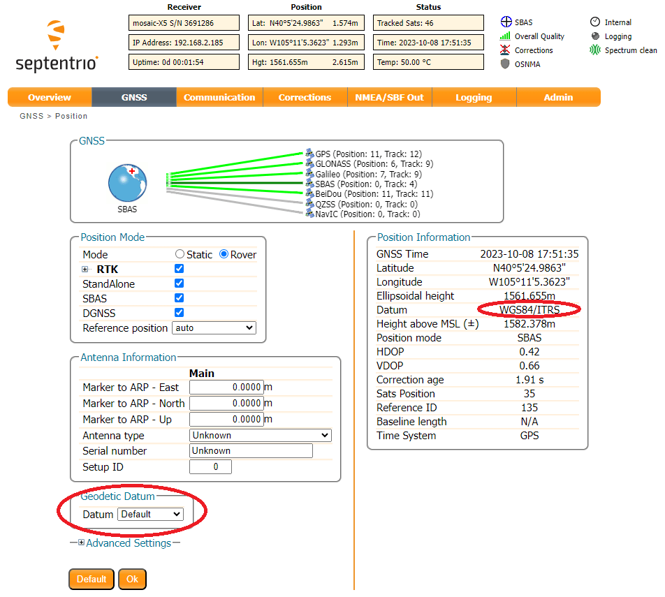
Set up an SBF logging stream to log PostProcess, Rinex, Rinex (meas3) with an interval of 1 sec:

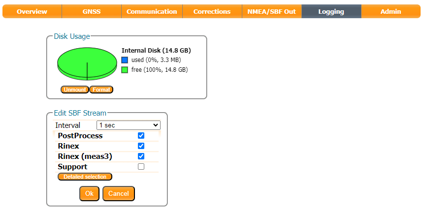
The IGS24H Naming Type is useful. When selected, the mosaic-X5 will log data in intervals of 24 hours, opening a new file at UTC midnight.
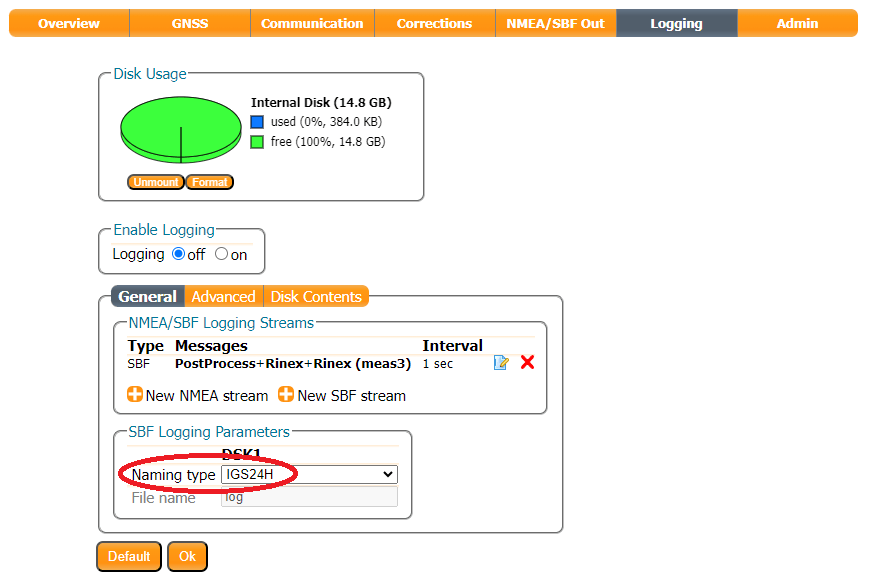
Use the Enable Logging radio button to start logging data, or press the LOG pushbutton. The red LOG LED will blink while data is being logged.
Use the Disk Contents tab to download the SBF data to your computer. Click the green arrow to download an individual file. Or - if the file is large - dismount the disk, eject it and use your computer to copy the files from microSD manually.
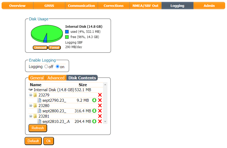
Use the RxTools SBF Converter utility to convert the data to RINEX format.

Upload the RINEX data to your chosen PPP post-process service. We have found NRCAN is very easy to use and produces excellent results. We select the ITRF tab because we are using the WGS84/ITRS datum. (If you are using NAD83, select that tab instead.)
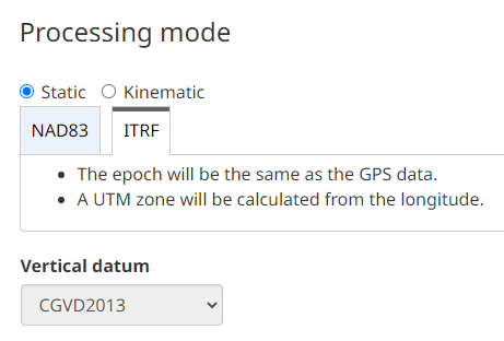
After you have uploaded your RINEX data, it only takes a few minutes to receive your antenna position:

Both OPUS and APPS have file size limits. You can shrink the size of the RINEX file by selecting (e.g.) a 30-second Epoch Interval in SBF Converter:

Using a smaller, 30-second file OPUS' ITRF results match NRCAN to within a cm:

We can now store those coordinates in the mosaic-X5 module memory, either as Geodetic (Latitude, Longitude, Altitude) or Cartesian (ECEF X/Y/Z) coordinates. The mosaic-X5 allows you to store 5 of each.


We can now generate corrections using that static / fixed antenna position.

RTK Configurations - NTRIP Server
Now we know the Base's antenna position accurately, we can generate and share RTK corrections in a number of ways. The mosaic-X5 is a very clever module and is able to share corrections through an NTRIP Caster, or direct using Serial, USB, or an IP connection. For example, here are the output options available for RTCMv3:

In the Advanced Settings, you can also define which messages to output and at what internal:
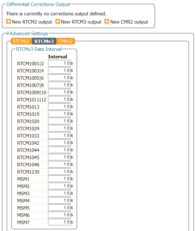
In this section, we are going to concentrate on sharing the corrections using an NTRIP Caster. Think of an NTRIP Caster as an intermediary, a way of sharing RTCM corrections between Bases and Rovers. There are several good free-to-use NTRIP Caster services available, including:
Here we are going to use RTK2go.
Create a New Base Station Reservation
Creating a New Reservation for your base station is really easy. Simply follow the instructions...
At SparkFun, we use MountPt names like bldr_dwntwn2 , bldr_dwntwn3 , bldr_SparkFun1 - bldr is short for Boulder. Choose a name that is short, easy to remember and - we suggest - includes clues about who you are or where your server is. You can see the full list of all active bases at rtk2go.com:2101.
The mosaic-X5 is a high-end receiver so be sure to select NTRIP Rev2 as the protocol and provide a login user name. IBAN - the banking network - provides a handy list of three-letter country codes.
The registration process typically takes under 8 hours to complete, somewhat longer on weekends. Once your mount point has been set up, RTK2go will send you a nice email confirming the mount point (mountPt) name, password and other details (Country, Country Code etc..). Make a note of those details, as we need to enter them into the mosaic-X5 NTRIP Server configuration.
Configure the NTRIP Server
Check that the Position Mode is set to Static, using either the precise position from your RINEX post-process data or an automatic Reference Position.
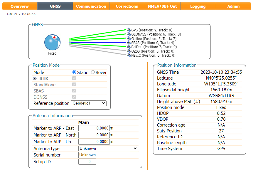
In the Corrections tab, select New NTRIP server:

Enter the details from the confirmation email:

Then use the Configure Output button to select the RTCM Output Type and which RTCM messages to send. Here we select RTCMv3. The mosaic-X5 supports both RTCMv2 and RTCMv3, but v3 has better data compression and message integrity so we will use that.
We also need to select which type of RTCM message to send. Here we select MSM7 since these are the longest highest precision messages. The message length does not matter since we are using Ethernet and WiFi, but it could be important if we were using Serial (UART) or LoRa to carry the correction messages.
Info
Remember to click the OK button at the bottom of the page, after making changes to update the current configuration. Also, don’t forget to save it to boot, if you want the configuration to persist when you cycle power.
All being well, you should see a green line for NTRIP showing that your corrections are being forwarded to the caster:

We can check RTK2go.com:2101 to see if the corrections are being received:

We can see more details by opening the Caster Status Report. Here I am using the Mount Point paulAtSparkFun, so the full report is available at rtk2go.com:2101/SNIP::MOUNTPT?baseName=paulAtSparkFun:
We've mentioned before that the mosaic-X5 is a very clever GNSS module. We can configure it to send corrections to multiple NTRIP Casters if desired, simply by adding extra NTRIP Caster Server connections.
RTK Configurations - NTRIP Client
Now that the Base mosaic-X5 is sending RTCM corrections to RTK2go via NTRIP, we can configure our Rover mosaic-X5 to use those corrections. We've mentioned before that the mosaic-X5 is a very clever GNSS module. We can configure it to use more than one NTRIP Caster or Correction Service. It will use the best data available to give an RTK fix. This is very handy if one of your correction sources goes offline, the mosaic-X5 will fall back to another.
The configuration process is exactly the same as we used for the Correction Service. We simply add another NTRIP Client.
In the Corrections tab, select New NTRIP client:
Enter the details of your RTK2go mount point. You don't need a password, but you do need to enter a username (email address) - a fake one is OK. The Mount point pull-down is populated after you enter the Caster and Port.

Remember to press OK after each change - and save the configuration.
All being well, you should now see two green lines for your two NTRIP correction sources:

Just for giggles, I placed the Rover and Base antennas 3' (3 feet = 0.914m) apart on the SparkFun building parapet. The Rover mosaic-X5 is showing 3mm horizontal accuracy and a Base-Rover baseline length of 0.917m. I am very happy with that!
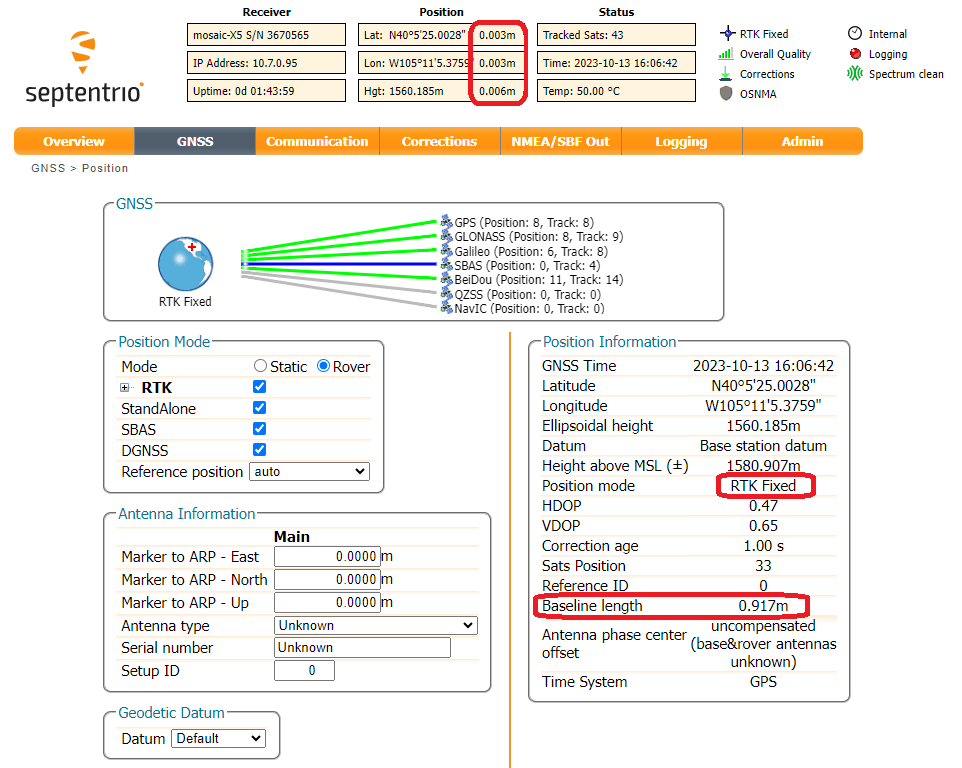
If you want to temporarily disable an NTRIP client, click the Edit NTRIP settings icon and then set the Mode to off. If you have two clients configured, this allows you to disable one and use the corrections from the other.
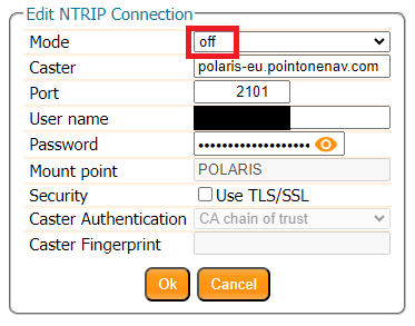
RTK Correction Service
In Real Time Kinematic (RTK) positioning, a Rover uses corrections from a local Base station to accurately augment its position to the centimeter level. This is done by using carrier-phase measurements of the received GNSS signals and differencing techniques. Put simply, an RTK Base knows where it is and - based on its location - can share satellite signal correction data with local Rovers, to allow them to achieve centimeter-level positioning.
NTRIP (Networked Transport of RTCM via Internet Protocol) is a standardized way of transferring RTCM correction data between RTK Bases and Rovers. It is the protocol used by NTRIP Casters for inbound and outbound corrections.
In this section, we are going to configure the mosaic-X5 as a Rover and have it use data from a commercial Correction Service which pools data from many base stations and provides you with corrections for your location.
To begin, check that the mosaic-X5 is configured as a Rover:

We've had good experiences with PointOneNav where you get a 14-day free trial without needing to give them your credit card details. Enter your details in the Create your account window, create an account and verify your email address. A Trial Device is created automatically. Make a note of the Caster address, Mount Point, Username and Password. You will need to enter those into the mosaic-X5 NTRIP Client configuration. We suggest bookmarking the link to the login page. If you are in Europe, the NTRIP Caster server is different. Please check the Polaris NTRIP API documentation for details. PointOneNav supports TLS encryption too. Again, please check the documentation for details.

In the Corrections tab, select New NTRIP client:
Enter the details of your PointOneNav Trial Device. The Mount point pull-down is populated after you enter the Caster and Port.
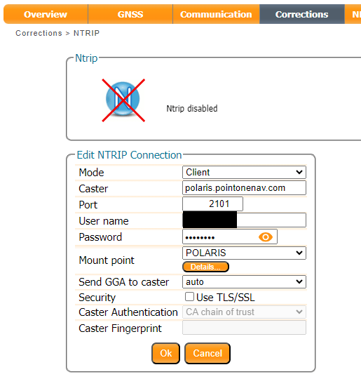
Remember to press OK after each change - and save the configuration.
Once the mosaic-X5 is connected to the correction service, you should get RTK Fixed almost instantly. It really is as simple as that. Here at SparkFun, we are able to get ~7mm accuracy using PointOneNav.
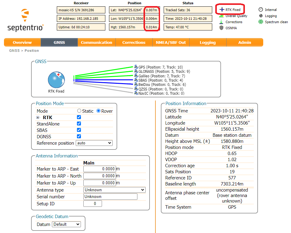
The NTRIP connection is two-way. The mosaic-X5 is sending its approximate position to the Correction Service so that the Correction Service can send us the best data for our location. Another thing we like about PointOneNav is that they display your location in the web dashboard. This is a very handy, simple way of seeing where your Rover devices are.

If we want to, we can find out where our correction data is coming from. 7mm is pretty darn good, so the Base must be quite close. It turns out it is just 7.3km north of our location. Open RxTools RxControl and connect to the mosaic-X5; USB is ideal or you can connect over your network using IP. Open the View DiffCorr Info View (Differential Correction Information View) and a window is displayed showing which RTCM stations we are connected to and the baseline distance(s). Double-click on the Station ID and another window pops up where the information and coordinates of the station can be seen.
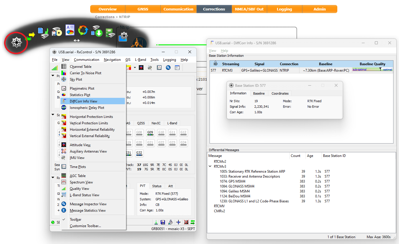
Enable the L5 Band
Supported GNSS Signals
The mosaic-X5 module is capable of receiving most of the GNSS signals from the various frequency bands of each constellation. By default, the module is only configured to track and receive signals (marked in green, in the table below) from specific satellites and frequency bands. Whereas, the signals marked in grey are also supported by the module, but each signal needs to be enabled before they can be utilized for (differential) positioning or output RTK correction data as well. Meanwhile, any signals colored in red and striked out are not supported by the mosaic-X5 module; likely due to their proprietary nature, existence outside the module's frequency range, or are under development/recently implemented.
| Frequency Band | |||||||||||||||
|---|---|---|---|---|---|---|---|---|---|---|---|---|---|---|---|
| L5/E5 | L2 | L6/E6 | L1/E1 | S | |||||||||||
|
GNSS Constellation
|
GPS | L5 | L2PY | L2C | L1CA | L1PY | |||||||||
| GLONASS | L3 | L2P | L2CA | L1CA | |||||||||||
| Galileo | E5a | E5b | E6BC | E1BC | |||||||||||
| Beidou | B2a | B2b | B2I | B3I | B1I | B1C | |||||||||
| SBAS | L5 | L1 | |||||||||||||
| QZSS | L5 | L2C | L1CA | L1C | |||||||||||
| Navic | L5 | ||||||||||||||
Legend for GNSS Signals
- Supported; Enabled by default
- Supported; Not enabled by default
Not supported
Enabling Signal Reception
Below, are instructions to configure the mosaic-X5 module to receive any of the supported GNSS signals that aren't enabled by default.
Web Interface
Enabling the GPS-L5 Signal
Currently, the GPS-L5 service is pre-operational and marked as "unhealthy"; therefore, extra configuration steps are required to enable this frequency band.
From the Admin tab, click on Expert Control from the drop-down menu. Then, navigate through the Control Panel > Navigation > Receiver Operation > Masks menus to find the Discard unhealthy satellites setting. Set both the Tracking and PVT options to off, from their drop-down menus.

Through the web interface, users will need to access the advanced settings of the configuration menu by clicking on the Expert Control option from the Admin tab's drop-down menu. Then, navigate through the Control Panel > Navigation > Advance User Settings menus.
Tracking > Signal Tracking : Enable GPSL5 signal tracking

Navigation > Advance User Settings > PVT > Signal Usage - Enable GPSL5 in both “PVT” and “navigation data decoder”
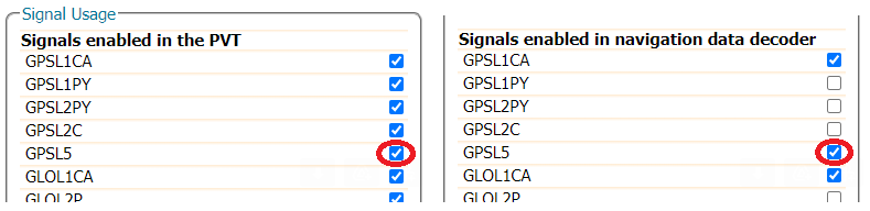
Info
Make sure to click the OK button at the bottom of each page, where you are making changes to update the current configuration. Also, don’t forget to save it to boot, if you want the configuration to persist when you cycle power.
Command Interface
GPS-L5 Signal
Since the GPS-L5 service is currently pre-operational and marked as "unhealthy", it takes some extra configuration steps to enable the GPS-L5 frequency band and corrections.
setHealthMask, Tracking, offsetHealthMask, PVT, off
setSignalTracking, +GPSL5setSignalUsage, +GPSL5, +GPSL5
Output L5 Corrections
Below, are instructions for outputting RTK corrections for the GPS L5 frequency band, from the RTK mosaic-X5.
Warning
The RTK mosaic-X5 must be configured to receive those GNSS signals (see instructions above); otherwise, it won't have any data to provide the corrections with.
Web Interface
From the drop-down menu of the Corrections tab of the web interface, select Corrections > Corrections Output to bring up the corrections output settings. On this page, locate the Advanced Settings menu, where users can define the data intervals and formatting. Clicking on this will prompt a security dialog box to pop up, click the Proceed button to make changes to these settings. RTK corrections for the GPS L5 frequency band are only available in the RTCMv3 messages; therefore, users will need to select the RTCMv3 tab.
Scroll down to the RTCMv3 Data Formatting section, select the box next to the GPSL5 to enable the RTK corrections for the GPS L5 frequency band. In the example below, we have enable all the available signals to be included in the MSM output messages.
Tip
Make sure to click the OK button at the bottom of each page, where you are making changes to update the current configuration. Also, don’t forget to save it to boot, if you want the configuration to persist when you cycle power.
Command Interface
setRTCMv3Formatting, 0, +GPSL5
Mining with Onocoy
Some RTK networks, such as Onocoy, offer users incentives for operating a reference station and contributing RTK corrections to their network. These incentives are often tied to a form of cryptocurrency, which is rewarded based upon a performance scale after the data is validated.
Warning
This section is for educational purposes only!
This section doesn't contain nor should it be represented as an endorsement of any of the projects mentioned nor as financial advice. Don’t invest anything you aren’t willing to lose.
Onocoy Documentation
Onocoy provides users with documentation for mining rewards with an RTK reference station. To get started, users will need to have installed and mounted the hardware of their RTK mosaic-X5 and created a user account with Onocoy. Then, users can obtain NTRIP server credentials from their account, to connect their reference station to the Onocoy network.
Onocoy documentaion for mining rewards.
Configure the RTK mosaic-X5
In order to connect their RTK mosaic-X5 to the Onocoy network, users will need to adjust the configurations of the mosaic-X5 and setup an NTRIP server to the Onocoy network.
Enable L5 Band Reception
Before setting up the RTK mosaic-X5 as an NTRIP server, users will need to enable the GPS L5 frequency band in order to provide corrections for it. These steps, are documented in the Enable the L5 Band section of this tutorial:
-
L5 Signal Reception
Below, are instructions to enable the RTK mosaic-X5 to receive GNSS signals from the GPS L5 frequency band.
Enabling the GPS-L5 Signal
Currently, the GPS-L5 service is pre-operational and marked as "unhealthy"; therefore, extra configuration steps are required to enable this frequency band.
From the Admin tab, click on Expert Control from the drop-down menu. Then, navigate through the Control Panel > Navigation > Receiver Operation > Masks menus to find the
Discard unhealthy satellitessetting. Set both the Tracking and PVT options tooff, from their drop-down menus.
Enabling the tracking and PVT use of signals from "unhealthy" satellites. Through the web interface, users will need to access the advanced settings of the configuration menu by clicking on the Expert Control option from the Admin tab's drop-down menu. Then, navigate through the Control Panel > Navigation > Advance User Settings menus.
Tracking > Signal Tracking : Enable GPSL5 signal tracking
L5 Configuration - Step 2 (PNG). Navigation > Advance User Settings > PVT > Signal Usage - Enable GPSL5 in both “PVT” and “navigation data decoder”
L5 Configuration - Step 3 (PNG). Info
Make sure to click the OK button at the bottom of each page, where you are making changes to update the current configuration. Also, don’t forget to save it to boot, if you want the configuration to persist when you cycle power.
Command Interface
GPS-L5SignalSince the GPS-L5 service is currently pre-operational and marked as "unhealthy", it takes some extra configuration steps to enable the GPS-L5 frequency band and corrections.
Connect to the Onocoy Network
In order to connect the RTK mosaic-X5 to the Onocoy network, users will need to set up an NTRIP caster in the mosaic-X5 configuration settings. In order to receive the rewards, Onocoy expects a specific set of configurations as listed in their online documentation.
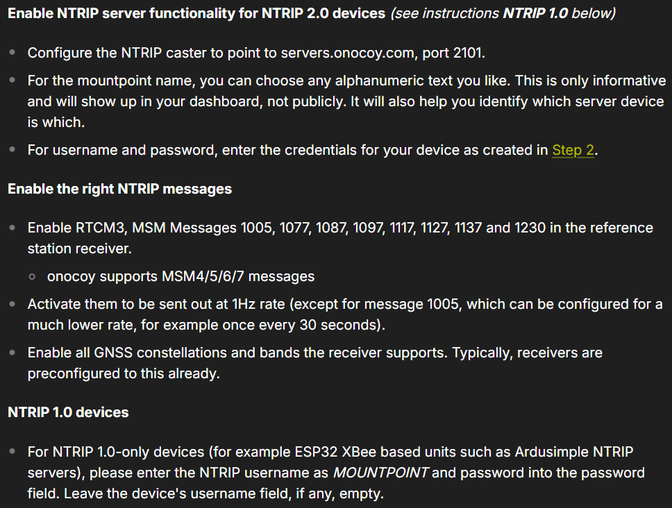
The specific parameters for connecting an NTRIP server to the Onocoy network, as listed in their documentation.
Most of steps for these requirements, are documented in the Configure the NTRIP Server section of this tutorial:
-
Configure the NTRIP Server
In the Corrections tab, select New NTRIP server:
Configuring the NTRIP server (PNG). Enter the details from the confirmation email:
Configuring the NTRIP server (PNG). Then use the Configure Output button to select the RTCM Output Type and which RTCM messages to send. Here we select RTCMv3. The mosaic-X5 supports both RTCMv2 and RTCMv3, but v3 has better data compression and message integrity so we will use that.
Ignore this information for this step
We also need to select which type of RTCM message to send. Here we select MSM7 since these are the longest highest precision messages. The message length does not matter since we are using Ethernet and WiFi, but it could be important if we were using Serial (UART) or LoRa to carry the correction messages.
Success
Instead of the confirmation email, use the information provided in the Onocoy documentation:
- Configure the NTRIP caster to point to
servers.onocoy.com, port2101. - For the
mountpointname, you can choose any alphanumeric text you like. This is only informative and will show up in your dashboard, not publicly. It will also help you identify which server device is which. - For
usernameandpassword, enter the credentials for your device as created in Step 2.
Info
Remember to click the OK button at the bottom of the page, after making changes to update the current configuration. Also, don’t forget to save it to boot, if you want the configuration to persist when you cycle power.
All being well, you should see a green line for NTRIP showing that your corrections are being forwarded to the caster:
Ignore this information for this step
We can check RTK2go.com:2101 to see if the corrections are being received:
Success
Instead, also select the RTCM messages listed in the Onocoy documentation. Below, are the RTCM messages we selected:
- Enable RTCM3, MSM Messages
1005,1077,1087,1097,1117,1127,1137, and1230in the reference station receiver. - onocoy supports MSM4/5/6/7 messages
We can see more details by opening the Caster Status Report. Here I am using the Mount Point paulAtSparkFun, so the full report is available at rtk2go.com:2101/SNIP::MOUNTPT?baseName=paulAtSparkFun:
- Configure the NTRIP caster to point to
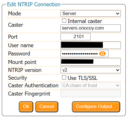
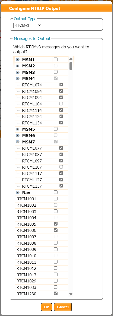
Enable L5 Corrections
The last step in configuring the NTRIP server, users will need to enable the GPS L5 signal to be included in the MSM output messages. This will allow the RTK mosaic-X5 to provide RTK corrections for the GPS L5 frequency band. These steps, are documented in the Output L5 Corrections section of this tutorial:
-
Output L5 Corrections
Below, are instructions for outputting RTK corrections for the GPS L5 frequency band, from the RTK mosaic-X5.
Web Interface
From the drop-down menu of the Corrections tab of the web interface, select Corrections > Corrections Output to bring up the corrections output settings. On this page, locate the Advanced Settings menu, where users can define the data intervals and formatting. Clicking on this will prompt a security dialog box to pop up, click the Proceed button to make changes to these settings. RTK corrections for the GPS L5 frequency band are only available in the RTCMv3 messages; therefore, users will need to select the RTCMv3 tab.
Advanced settings for RTCMv3 Output (PNG). Scroll down to the RTCMv3 Data Formatting section, select the box next to the
GPSL5to enable the RTK corrections for the GPS L5 frequency band. In the example below, we have enable all the available signals to be included in the MSM output messages.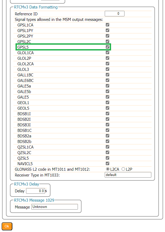
Advanced settings for RTCMv3 Data Formatting (PNG). Tip
Make sure to click the OK button at the bottom of each page, where you are making changes to update the current configuration. Also, don’t forget to save it to boot, if you want the configuration to persist when you cycle power.
Command Interface
setRTCMv3Formatting, 0, +GPSL5
Receive Rewards
Once users have connected the RTK mosaic-X5 as an NTRIP server on the Onocoy network, there are a few additional steps in that need to be completed, a specified in their online documentation.
Happy Mining!
Resources
Product Resources
Additional Resources
🏭 Manufacturer's Resources
Septentrio also provides great resources for the mosaic-X5:
-
Recommended Articles
General Knowledge
mosaic - Getting started
Resetting a receiver
Resetting and clearing the non-volatile memory
Generating a diagnostic report of a Septentrio receiver
RTCMv3 messages supported by the Septentrio receivers
Interference Detection, Mitigation, and FlaggingProviding Corrections
How to set up a base station
RTK positioning with a moving baseline
Set up an (internal) NTRIP caster on a Septentrio receiverApplying Corrections
Receive corrections over IP
Receive corrections via NTRIP
Using uBlox's correction services for precise positioningAntenna Corrections
-
Recommended Videos
Getting started with the mosaic receiver module
Output NMEA data on the mosaic receiver module
Receiving NTRIP corrections on the mosaic module
Logging data to the Septentrio mosaic receiver module
Receiving corrections over an IP connection
Share the USB internet connection on your receiver
Septentrio's Agnostic GNSS Corrections program
Test-run for Septentrio's anti-jamming feature
mosaic - GNSS module receiver range from Septentrio

Troubleshooting Tips
Need Help?
If you need technical assistance or more information on a product that is not working as you expected, we recommend heading over to the SparkFun Technical Assistance page for some initial troubleshooting.
If you can't find what you need there, the SparkFun GNSS Forum is a great place to ask questions.
Account Registration Required
If this is your first visit to our forum, you'll need to create a Forum Account to post questions.
What is in the Box?
The RTK mosaic-X5 comes packaged as a complete kit, with all the accessories you'd need to set up an RTK base station. Inside the box, users will find the GNSS antenna, RTK mosaic-X5 in its aluminum enclosure, and another box containing additional accessories. Inside, the accessory box, users will find the CAT-6 Ethernet cable, USB cable, SMA to TNC cable, USB power supply, WiFi antenna, and 32GB SD card.
Everything that is included in the RTK mosaic-X5 kit.
The contents of the RTK mosaic-X5 package.
Products in the accessories box.
If you are missing any of these items, please reach out to us in our forum.
WiFi Connectivity
For WiFi connectivity issues, here are some simple troubleshooting tips:
- Verify that the RTK mosaic-X5 is operating in Mode:
2for WiFi functionality. - Double-check the WiFi credentials used in the ESP32 configuration.
- Make sure that the configured WiFi network is broadcasting on a 2.4GHz band. The ESP32 cannot access the 5GHz band.
- Make sure that the Ethernet cable is not coiled around/near the WiFi antenna. This will cause data packets to be lost and the mosaic-X5 web page to hang/freeze.
WiFi Provisioning
The ESP32 firmware we provide is only compatible with basic SSID and Password WiFi authentication. The firmware is not compatible with networks that implement other provisioning methods such as a captive portal, a QR code, or Wi-Fi protected setup. Our intention was that users could easily develop their, own firmware to suit their needs.
Tip
Here are some resources that might be useful for getting started with other provisioning methods:
Data Logging
For data logging issues, here are some simple troubleshooting tips:
- Make sure that your SD card is formatted to a
FAT32file system.- The
FAT32file system also limits the maximum capacity of the card to less than 32GB (i.e. a 256GB SD card will not work).
- The
- Make sure that the mosaic-X5 module has a configured data stream output.
- Use the mosaic-X5 web page to verify that the SD card is mounted as a storage drive.
OLED Dead Pixels
Got a few dead pixels on your OLED display? Please reach out to us in our forum.
Vehicle Power - Dead Battery
Is the RTK mosaic-X5 killing your vehicle's battery?
Make sure that the external power source for the RTK mosaic-X5 is not directly tied to the vehicle's battery, Always On, or accessory circuits. Otherwise, users will risk killing the battery while the engine is off. We recommend locating the ignition on or switched power circuit, which is only powered when the key is in the On position and the engine is running.
Note
The On position, is where a key normally rests after the engine is started. However, users can still move the key from the Off position and into the On position without starting the engine. In this case, the alternator is not running and keeping the battery charged.
Modern eco-efficient vehicles may automatically shut down the engine if the vehicle is idling too long. Therefore, cutting off the vehicle's alternator that keeps the battery charged. Luckily, most vehicles with this automatic start/stop technology will monitor the battery's voltage and restart the engine when required. With this in mind, users may want to initially monitor their battery voltage, in case their vehicle isn't "so smart" .
L5 Band
By default, the L5 band is disabled on the mosaic-X5. To enable reception of the L5 band on the mosaic-X5, we have provided instructions on the Enable the L5 Band page.
Expected Accuracy
Here is a reference of the accuracy that can be expected from the RTK mosaic-X5 at a stationary position in Rover mode.
With the factory settings for the mosaic-X5, our location had a standard deviation of σx = 0.499m and σy = 0.595m
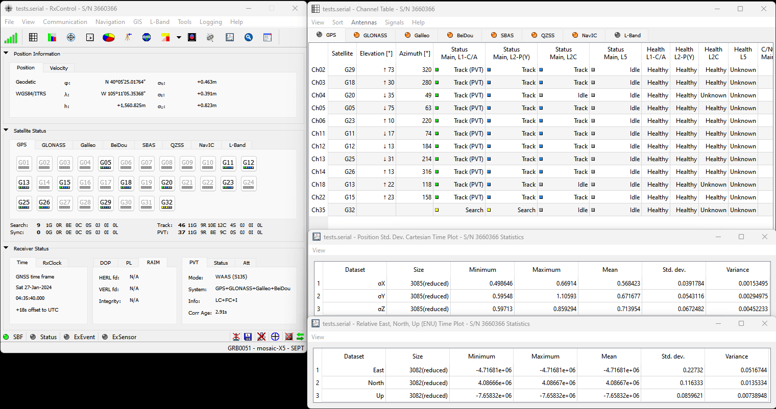
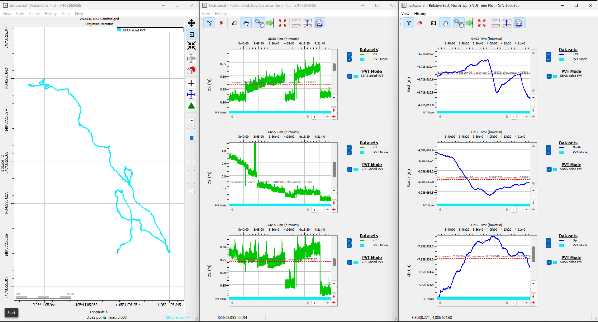
Conditions: L1/L2/L5 band antenna, statically mounted to the rooftop of our building, featuring a significant ground plane, with no obstructions for multi-path signals. The RTK mosaic-X5 was connected with a low-loss cable, fully powered at 5V, and default settings.
With the default settings and the L5 band enabled for the mosaic-X5, our location had a standard deviation of σx = 0.504m and σy = 0.673m
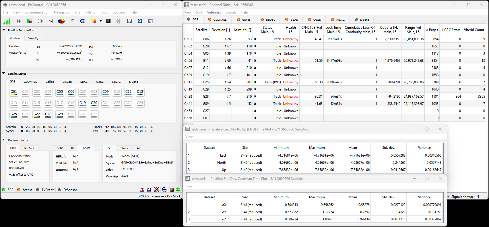
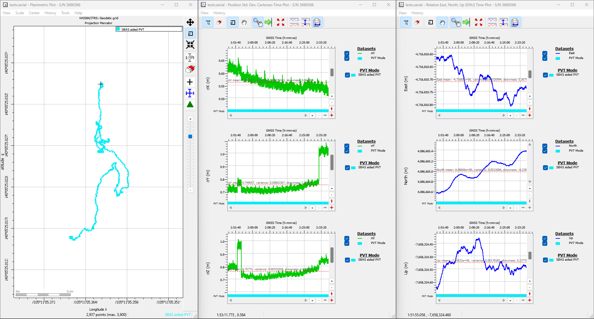
Conditions: L1/L2/L5 band antenna, statically mounted to the rooftop of our building, featuring a significant ground plane, with no obstructions for multi-path signals. The RTK mosaic-X5 was connected with a low-loss cable, fully powered at 5V, and had the L5 band enabled.
With the default setting and RTK corrections enabled for the mosaic-X5, our location had a standard deviation of σx = 4.29mm and σy = 6.65mm
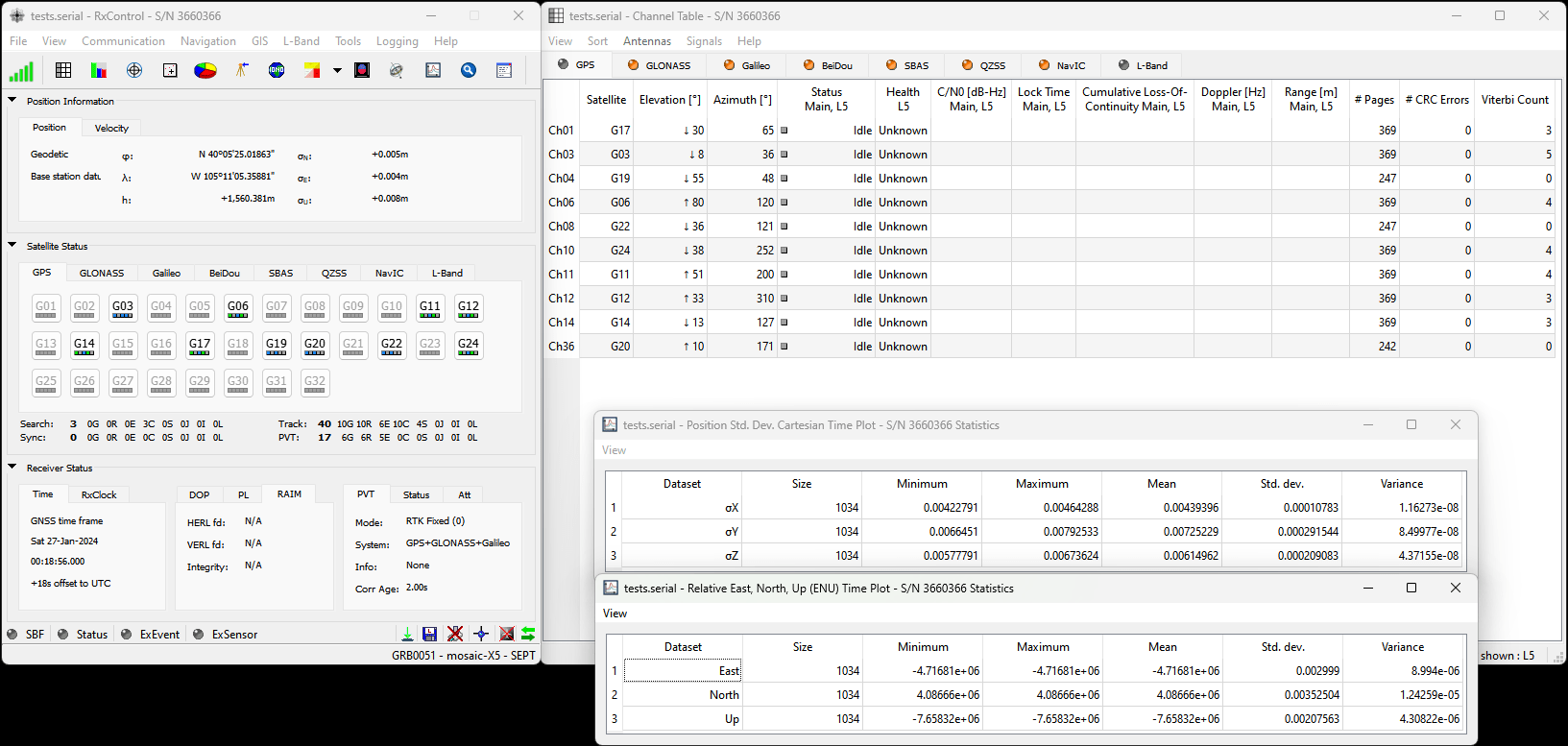
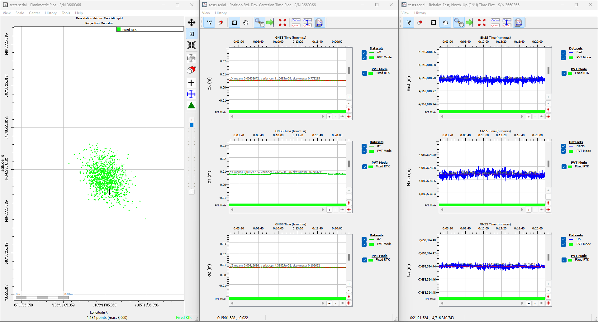
Conditions: L1/L2/L5 band antenna, statically mounted to the rooftop of our building, featuring a significant ground plane, with no obstructions for multi-path signals. The RTK mosaic-X5 was connected with a low-loss cable, fully powered at 5V, and configured as an NTRIP client with corrections from RTK2go.
Under "ideal conditions", our location had a standard deviation of σx = 4.68mm and σy = 6.70mm
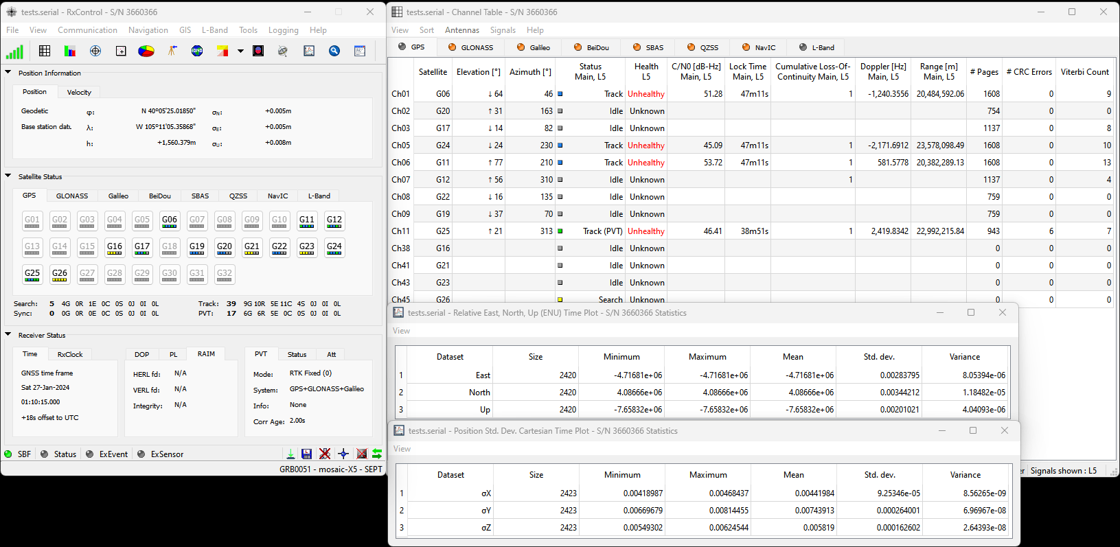
L5 band enabled.
Ideal: L1/L2/L5 band antenna, statically mounted to the rooftop of our building, featuring a significant ground plane, with no obstructions for multi-path signals. The RTK mosaic-X5 was connected with a low-loss cable, fully powered at 5V, RTK corrections enabled, and configured to enable the L5 band.
Reprogramming the ESP32
In case users accidentally reprogram or corrupt the flash memory on the ESP32, the factory firmware is available in our GitHub repository.
The batch files in the linked directory are used to flash our factory firmware onto the ESP32 in the RTK mosaic-X5. The batch file relies on the tools from the Arduino IDE and the ESP32 Arduino core and therefore, they will need to be installed before the batch file can be executed.
Note
The batch file is only compatible with Windows computers. For Linux and MacOS, users will need to manually flash the binary files onto the ESP32.
Note
To compile the firmware, users will need to install the ESP-IDF, Espressif's development framework for the ESP32. However, the compilation instructions are outside the scope of our support for this product. However, users can refer to the programming guide for the ESP-IDF to figure out how to compile the firmware.
Enclosure Disassembly
Due to the ESD sensitivity of the mosaic-X5 module, we don't recommend disassembling the RTK mosaic-X5. However, if users must access the PCB to troubleshoot an issue, make a modification, or repair a component, we highly recommend that they take the necessary ESD precautions to avoid damaging the mosaic-X5 module.
Read Before Disassembly!
ESD Sensitivity
The mosaic-X5 module is sensitive to ESD. Use a proper grounding system to make sure that the working surface and the components are at the same electric potential.
ESD Precaution
As recommended by the manufacturer, we highly encourage users to take the necessary precautions to avoid damaging their module.
- The RTK mosaic-X5 features ESD protection on the USB-C connectors and ethernet jacks.
- The mosaic-X5 module features internal ESD protection to the
ANT_1antenna input.
-
iFixit Anti-Static Wrist Strap
TOL-25572
Before disassembling the enclosure, users should disconnect the power and all cables from the RTK mosaic-X5. This will prevent users from creating any shorts and will facilitate the teardown process further on.
The RTK mosaic-X5 PCB is held in place by the front and rear panels of the enclosure. While users can remove the panels first, we recommend that users disconnect the screw terminal blocks first. Users may find it more difficult to separate the terminal block from the connector later in the disassembly process.
Remove the Screw Terminal Block First
Users may find it easiest to remove the screw terminal blocks first; as opposed to later in the teardown process.
Users can wiggle or use a soft/rigid object to carefully pry the terminal block off. In the picture above, a plastic name tag (~1.5mm thick) is used to carefully pry the terminal block up. We have also found the edge of a PCB ruler works great too.
Once the terminal blocks have been removed, users can remove the front and rear panels of the enclosure. They are held in place with four, M3, Phillips head screws on the corners of each panel.
Tip
We recommend removing the front panel first to prevent the Qwiic cable from being yanked off the OLED display or main PCB. Once the front panel is free, carefully lift the panel and disconnect the Qwiic cable from the top connector on the OLED display.
At this point, if users have previously disconnected all the cables and the terminal blocks from the back, the RTK mosaic-X5 PCB should slide out of the enclosure. Users can then, remove the rear panel from the enclosure to complete the teardown process.
-
On Linux, the standard Linux CDC-ACM driver is suitable. ↩↩↩
-
The system requirements and installation instructions are from the RxTools v22.1.0 user manual. This information may change in later iterations of the software suite. Please refer to the user manual (of the version you are utilizing) for the most accurate information. ↩↩
-
Higher data rates will require higher CPU speed and more memory capacity. ↩
-
Users will need administrative privileges to install the RxTools software. ↩↩
-
Users may need to extract the RxTools installation files from the downloaded, compressed file. ↩↩
-
Please see the release notes for the issues and limitations of the RxTools applications. ↩
-
Requires c privileges. ↩
-
Changing these permissions also requires
rootprivileges. ↩ -
For the latest USB driver from Septentrio, please install their driver through the RxTools software suite.
This driver version was archived at the time that the mosaic-X5 hookup guide was written. Please do not request for the file to be updated. ↩