Example - Basic
Hardware Assembly
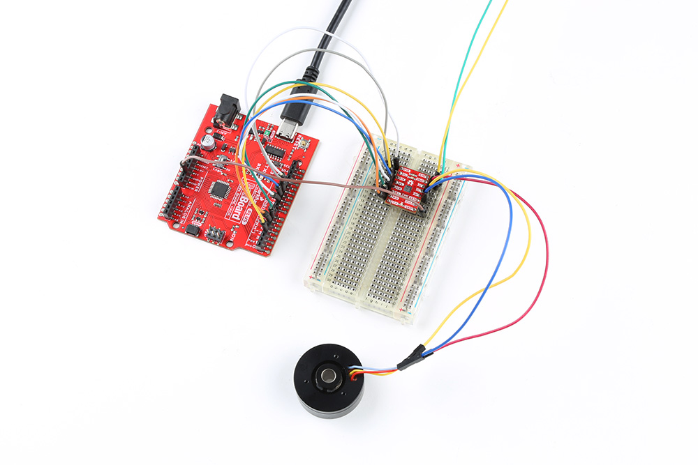
Users should already have followed the instructions from the component assembly and example setups sections to setup their hardware for this example.
A graphical representation of the connections between the RedBoard Plus and a breadboard with the TMC6300 motor driver attached.
RedBoard Plus to TMC6300
Connect the following pins from the RedBoard Plus to the TMC6300.
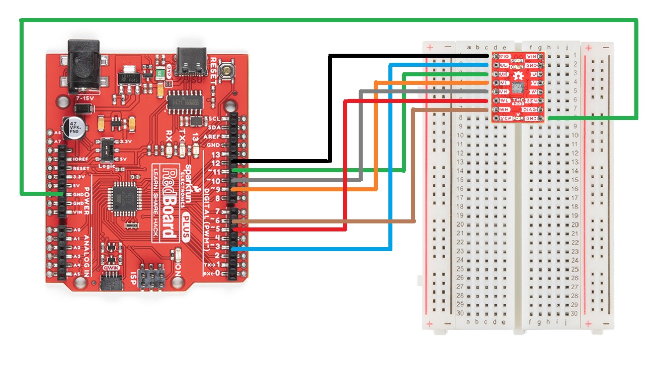
A graphical representation of the connections between the RedBoard Plus and a breadboard with the TMC6300 motor driver attached.
Connecting the Gimbal Motor
Connecting a 3-phase, BLDC motor to the motor driver is relatively simple as the sequence of the wires connection doesn't matter. Using jumper wires, connect the prepared ends of the gimbal stabilizer motor to the U, V, and W pins of the TMC6300 breakout board.
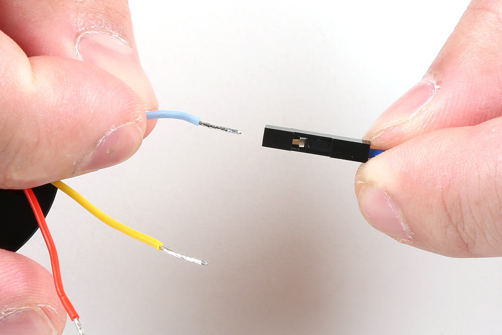
A prepared end of the gimbal motor being inserted into the female terminals of a jumper wire.
Powering the TMC6300
If users are unable to find a suitable power source, we have found that the 5V power output from the RedBoard Plus is sufficient to drive the gimbal motor, under a no load condition at low speeds.

A graphical representation of the connections between the RedBoard Plus and a breadboard with the TMC6300 motor driver attached.
Example Code
After installing and setting up the Arduino IDE and the Simple FOC Arduino library, users will need to upload the following example code to the RedBoard Plus. This code can be copied or downloaded below:
Example Code
    // Open loop motor control example
    #include <SimpleFOC.h>


    // BLDC motor & driver instance
    // BLDCMotor motor = BLDCMotor(pole pair number);
    BLDCMotor motor = BLDCMotor(7);
    // BLDCDriver3PWM driver = BLDCDriver3PWM(pwmA, pwmB, pwmC, Enable(optional));
    BLDCDriver6PWM driver = BLDCDriver6PWM(5, 6, 9,10, 3, 11);

    // Stepper motor & driver instance
    //StepperMotor motor = StepperMotor(50);
    //StepperDriver4PWM driver = StepperDriver4PWM(9, 5, 10, 6,  8);


    //target variable
    float target_velocity = 6;

    // // instantiate the commander
    Commander command = Commander(Serial);
    // void doTarget(char* cmd) { command.scalar(&target_velocity, cmd); }
    // void doLimit(char* cmd) { command.scalar(&motor.voltage_limit, cmd); }

    void setup() {

      // driver config
      // power supply voltage [V]
      driver.voltage_power_supply = 5;
      // limit the maximal dc voltage the driver can set
      // as a protection measure for the low-resistance motors
      // this value is fixed on startup
      driver.voltage_limit = 5;
      // pwm frequency to be used [Hz]
      // for atmega328 fixed to 32kHz
      // esp32/stm32/teensy configurable
      driver.pwm_frequency = 32000;


      driver.init();
      // link the motor and the driver
      motor.linkDriver(&driver);

      // limiting motor movements
      // limit the voltage to be set to the motor
      // start very low for high resistance motors
      // current = voltage / resistance, so try to be well under 1Amp
      motor.voltage_limit = 3;   // [V]

      // open loop control config
      motor.controller = MotionControlType::velocity_openloop;

      // init motor hardware
      motor.init();

      // add target command T
      // command.add('T', doTarget, "target velocity");
      // command.add('L', doLimit, "voltage limit");

      Serial.begin(115200);
      Serial.println("Motor ready!");
      Serial.println("Set target velocity [rad/s]");
      _delay(1000);

    }

    void loop() {

      // open loop velocity movement
      // using motor.voltage_limit and motor.velocity_limit
      motor.move(target_velocity);

      // user communication
      command.run();


    }
Running the Motor
Be default, the motor should spin automatically. However, if users wish to control the speed of the motor, they can uncomment lines 21-22 and 56-57 of code and reprogram the RedBoard Plus.
Code Changes Highlighted
Uncomment the following lines of code (21-22 and 56-57):
    // Open loop motor control example
    #include <SimpleFOC.h>


    // BLDC motor & driver instance
    // BLDCMotor motor = BLDCMotor(pole pair number);
    BLDCMotor motor = BLDCMotor(7);
    // BLDCDriver3PWM driver = BLDCDriver3PWM(pwmA, pwmB, pwmC, Enable(optional));
    BLDCDriver6PWM driver = BLDCDriver6PWM(5, 6, 9,10, 3, 11);

    // Stepper motor & driver instance
    //StepperMotor motor = StepperMotor(50);
    //StepperDriver4PWM driver = StepperDriver4PWM(9, 5, 10, 6,  8);


    //target variable
    float target_velocity = 6;

    // // instantiate the commander
    Commander command = Commander(Serial);
    // void doTarget(char* cmd) { command.scalar(&target_velocity, cmd); }
    // void doLimit(char* cmd) { command.scalar(&motor.voltage_limit, cmd); }

    void setup() {

      // driver config
      // power supply voltage [V]
      driver.voltage_power_supply = 5;
      // limit the maximal dc voltage the driver can set
      // as a protection measure for the low-resistance motors
      // this value is fixed on startup
      driver.voltage_limit = 5;
      // pwm frequency to be used [Hz]
      // for atmega328 fixed to 32kHz
      // esp32/stm32/teensy configurable
      driver.pwm_frequency = 32000;


      driver.init();
      // link the motor and the driver
      motor.linkDriver(&driver);

      // limiting motor movements
      // limit the voltage to be set to the motor
      // start very low for high resistance motors
      // current = voltage / resistance, so try to be well under 1Amp
      motor.voltage_limit = 3;   // [V]

      // open loop control config
      motor.controller = MotionControlType::velocity_openloop;

      // init motor hardware
      motor.init();

      // add target command T
      // command.add('T', doTarget, "target velocity");
      // command.add('L', doLimit, "voltage limit");

      Serial.begin(115200);
      Serial.println("Motor ready!");
      Serial.println("Set target velocity [rad/s]");
      _delay(1000);

    }

    void loop() {

      // open loop velocity movement
      // using motor.voltage_limit and motor.velocity_limit
      motor.move(target_velocity);

      // user communication
      command.run();


    }
In order to drive the motor, users will need to access the serial monitor and provide the commands necessary to drive the motor. A full list of the available commands can be found in the Simple FOC Arduino library documentation. However, only the T and L commands are enabled in the example code.
- Sending a
Tcommand will set the target motor velocity in rads/s- Example - Entering
T6into the serial monitor, will set the target motor velocity to 6 radians/s.
- Example - Entering
- Sending a
Lcommand will set the voltage limit of the motor driver and in turn, the current limit (voltage_limit / motor_resistance)- Example - Entering
L5into the serial monitor, will set the voltage limit to 5V and the current limit to .5A (5V/10Ω).
- Example - Entering
Baud Rate
THe serial monitor baud rate should be configured to 115200bps.