Hardware Components
TMC6300 Motor Driver
Headers
New to soldering?
If you have never soldered before or need a quick refresher, check out our How to Solder: Through-Hole Soldering guide.

The pins on the SparkFun TMC6300 motor driver are broken out to 0.1"-spaced pins on the outer edges of the board. When selecting headers, be sure you are aware of the functionality and board orientation required.
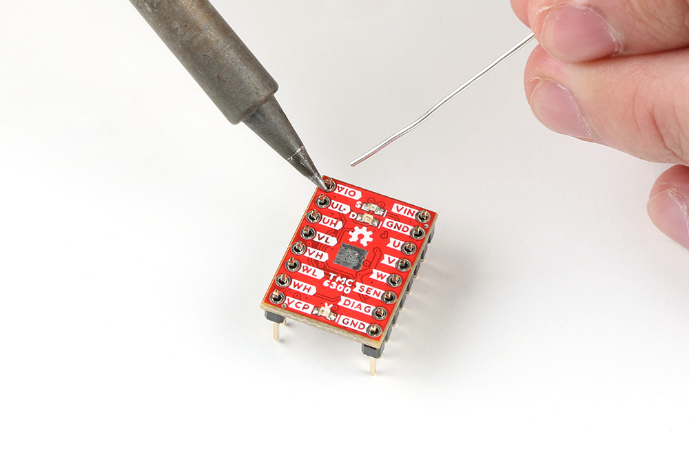
Soldering headers to the TMC6300 motor driver.
Tip
Please be aware that the side of the board with the silkscreen labeld for the pins and the heat sink pad is, technically the top side of the board when in use.
-
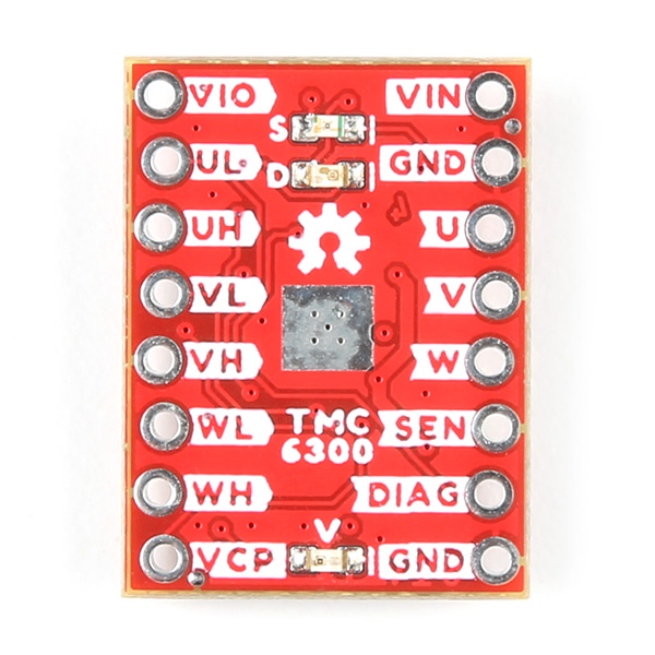
Top side of the TMC6300 motor driver. -

Bottom side of the TMC6300 motor driver.
Staggered PTH Pins
The pins on the board may appear to be offset or crooked; this is by design, we stagger the holes along a specific center alignment. This reduces the geometric tolerance between the holes and header pins along a single axis, which helps to hold the header in place and keeps the pins more orthogonal to the board when soldering.
Heat Sink
Tip
With larger heat sinks, we recommend a test fit and attaching it last to avoid conflicts with other parts of the board. For example, the heat sink could block the PTH pins/slots or access to the jumper pad.
Copper Heat Sink
Users may be tempted to use our copper heatsink on their board. However, we highly advise against using the copper heat sink because it barely fits and will likely cause a short across one of the pins.
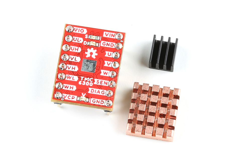 Different heat sinks next to the TMC6300 motor driver. |
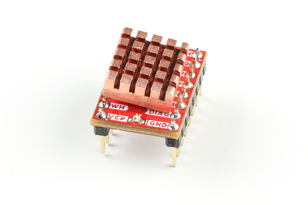 Copper heat sink not fitting on the TMC6300 motor driver. |
To attach a heat sink to the board, users will also need a piece of thermal tape. We recommend the following procedure:
-
Cut out a piece of thermal tape to fit the bottom of the heat sink.
Tip
Covering the entire bottom of the heat sink can insulate the electrical contacts on the board from shorting.
- For a perfect fit, users can place the heat sink over the tape and trace the outline to cut with scissors.
- For a perfect fit, users can also place the heat sink over the tape and cut the outline with a hobby knife.
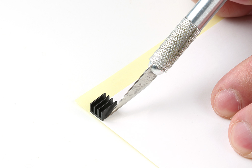
Cutting the thermal tape to fit the heat sink. -
Place the piece of thermal tape on the bottom of the heat sink.
Tip
We recommend peeling off just one side of the backing sheet or release liner to place the thermal tape on the heat sink. Users can then peel the other side off when they are ready to place the heat sink on their board.
-
Attach the heat sink to the board.
- Make sure to make any jumper modifications and/or solder any connections before placing the heat sink on the board.
- Make sure to avoid any electrical contact with the sides of the heat sink.

Heat sink attached to the TMC6300 motor driver.
BLDC Gimbal Motor
Advanced Skills Required
To connect the gimbal motor to the TMC6300 motor driver board, some advanced soldering and wire stripping skills are necessary. The wire leads from the motor are only about 2" long, which is not a lot to work with. Users may only have two attempts at stripping the wires before they run out the available wire length.
New to soldering?
If you have never soldered before or need a quick refresher, check out our How to Solder: Through-Hole Soldering guide.
To connect the gimbal motor to the TMC6300 motor driver, users will need to expose the wiring. First, remove the JST connector and make sure to cut as close to the plastic housing as possible.
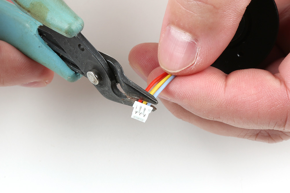
Cut off the plastic JST connector on the motor's wire leads.
Alternative Connections
If users are utilize the alligator or IC hook pigtails, they may be able to crack the plastic housing of the connector to expose the crimped wire terminals.
Next, with as much care as possible, strip off some of the electrical insulation of each of the leads. On our wire strippers, the 26AWG notch worked the best.
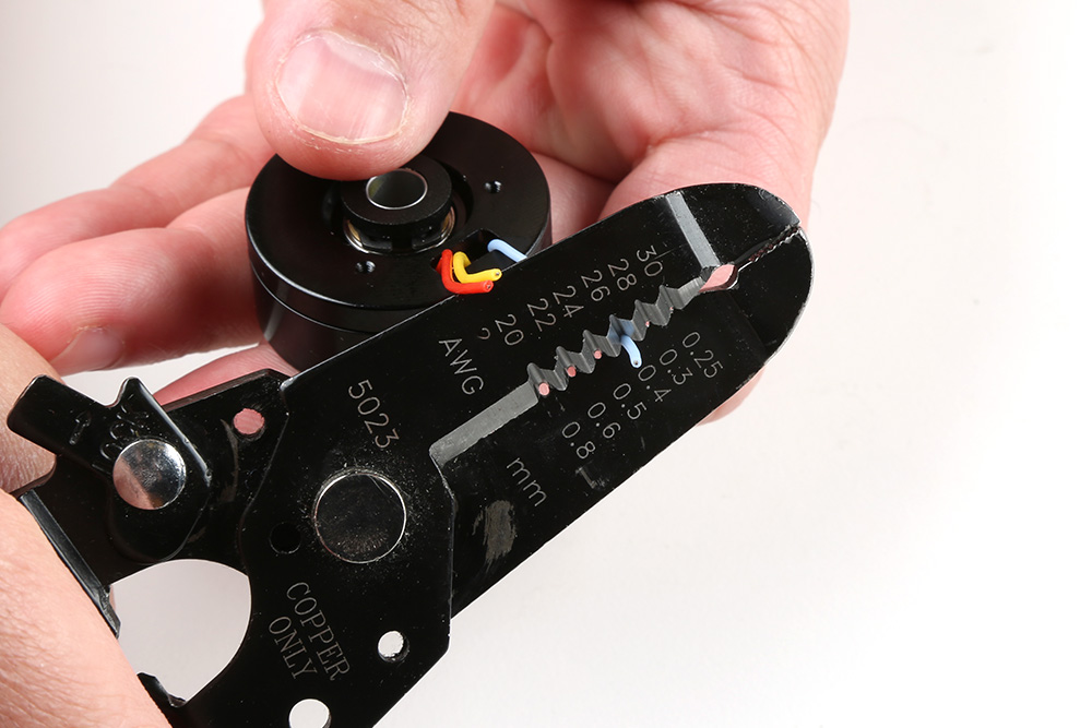
Strip off some of the insulation from the motor's wire leads.
The last step is to twist and tin the wires, so that they can be inserted into some jumper wires. Make sure to keep the ends straight and avoid adding to much solder, so that the wire ends can still fit into the female jumper wire terminals.
 Twist and tin the exposed wire leads, so that they can be inserted into the female end of a jumper wire. |
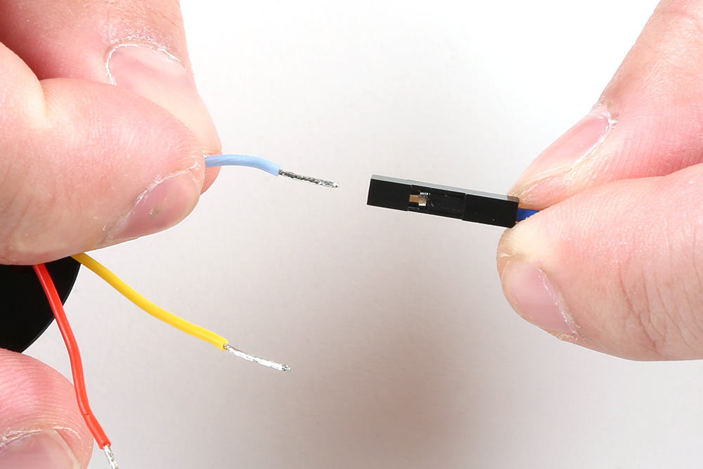 The leads should be straight and clear of bulges fit the into female terminals. |