Example - H-Bridge
Hardware Assembly
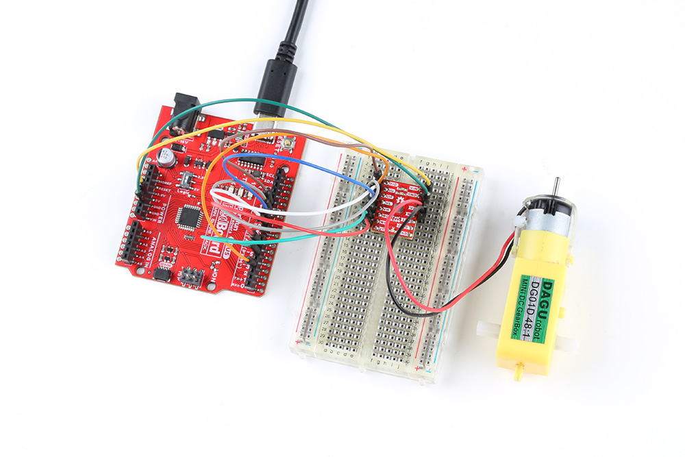
Users should already have followed the instructions from the component assembly and example setups sections to setup their hardware for this example.
A graphical representation of the connections between the RedBoard Plus and a breadboard with the TMC6300 motor driver attached.
RedBoard Plus to TMC6300
Connect the following pins from the RedBoard Plus to the TMC6300.
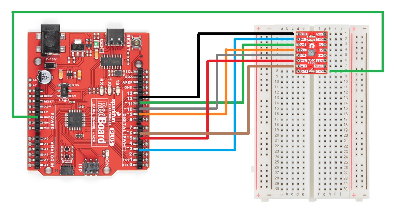
A graphical representation of the connections between the RedBoard Plus and a breadboard with the TMC6300 motor driver attached.
Connecting the DC Motor
If this was a H-bridge motor driver, the connections to the motor wouldn't matter. However, as there are three half-bridges, users will need to note which half-bridges the DC motor is connected to. These connections will dictate how the motor is driven by the software. For the example, connect the motor to the V and W output channels of the TMC6300 motor driver.
Powering the TMC6300
If users are unable to find a suitable power source, we have found that the 5V power output from the RedBoard Plus is sufficient to drive the gimbal motor, under a no load condition at low speeds.

A graphical representation of the connections between the RedBoard Plus and a breadboard with the TMC6300 motor driver attached.
Example Code
After installing and setting up the Arduino IDE and the Simple FOC Arduino library, users will need to upload the following example code to the RedBoard Plus. This code can be copied or downloaded below:
Example Code
    // BLDC driver standalone example
    #include <SimpleFOC.h>

    // BLDC driver instance
    BLDCDriver6PWM driver = BLDCDriver6PWM(5, 6, 9,10, 3, 11);

    void setup() {

      // pwm frequency to be used [Hz]
      // for atmega328 fixed to 32kHz
      // esp32/stm32/teensy configurable
      driver.pwm_frequency = 32000;
      // power supply voltage [V]
      driver.voltage_power_supply = 5;
      // Max DC voltage allowed - default voltage_power_supply
      driver.voltage_limit = 5;
      // daad_zone [0,1] - default 0.02f - 2%
      driver.dead_zone = 0.05f;

      // driver init
      driver.init();

      // enable driver
      driver.enable();

      _delay(1000);
    }

    void loop() {
        driver.setPwm(5,0,0);
        _delay(1000);

        driver.setPwm(0,5,0);
        _delay(1000);
    }
Running the Motor
Be default, the motor should spin automatically. However, if users wish to control the motor, they can modify lines 30 and 33 of code and reprogram the RedBoard Plus. These lines control the high and low-side MOSFETS of the H-bridge directly through pins 5, 6, 9, and 10.
Code Changes Highlighted
MOdify the following lines of code (30 and 33):
    // BLDC driver standalone example
    #include <SimpleFOC.h>

    // BLDC driver instance
    BLDCDriver6PWM driver = BLDCDriver6PWM(5, 6, 9,10, 3, 11);

    void setup() {

      // pwm frequency to be used [Hz]
      // for atmega328 fixed to 32kHz
      // esp32/stm32/teensy configurable
      driver.pwm_frequency = 32000;
      // power supply voltage [V]
      driver.voltage_power_supply = 5;
      // Max DC voltage allowed - default voltage_power_supply
      driver.voltage_limit = 5;
      // daad_zone [0,1] - default 0.02f - 2%
      driver.dead_zone = 0.05f;

      // driver init
      driver.init();

      // enable driver
      driver.enable();

      _delay(1000);
    }

    void loop() {
        driver.setPwm(5,0,0);
        _delay(1000);

        driver.setPwm(0,5,0);
        _delay(1000);
    }
- The PWM voltage value
driver.setPwm(voltage_value,0,0)affects the speed of the motor. - The position of this value inr elation to the PWM drive channel
driver.setPwm(channel_v,channel_w,0)affects the direction.
Tip
Users may also be interested in the SimpleDC Motor library to drive DC motors with the Simple FOC Arduino library.