Arduino IDE
Tip
For first-time users, who have never programmed before and are looking to use the Arduino IDE, we recommend beginning with the SparkFun Inventor's Kit (SIK), which is designed to help users get started programming with the Arduino IDE.
Most users may already be familiar with the Arduino IDE and its use. However, for those of you who have never heard the name Arduino before, feel free to check out the Arduino website. To get started with using the Arduino IDE, check out our tutorials below:
What is an Arduino? |

Installing Arduino IDE |
Installing an Arduino Library |
Installing Board Definitions in the Arduino IDE |
-
What is an Arduino?
-
Installing the Arduino IDE
-
Installing an Arduino Library
-
Installing Board Definitions in the Arduino IDE
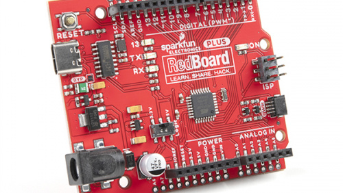
Need help setting up the RedBoard Plus?
RedBoard Plus
The following instructions should help users get started with the RedBoard Plus. For more information about the board, please check out our hookup guide below:
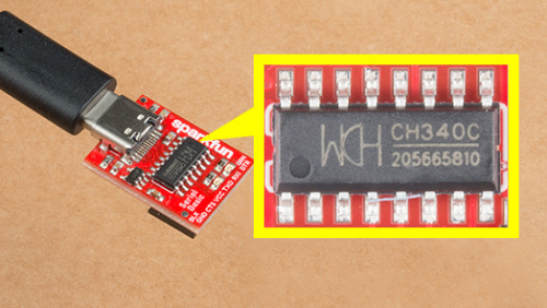
CH340 Driver
Users will need to install the appropriate driver for their computer to recognize the serial-to-UART chip on their board/adapter. Most of the latest operating systems will recognize the CH340C chip on the board and automatically install the required driver.
To manually install the CH340 driver on their computer, users can download it from the WCH website. For more information, check out our How to Install CH340 Drivers Tutorial.
Arduino IDE
When selecting a board to program in the Arduino IDE, users should select the Arduino Uno from the Tools drop-down menu (_i.e. Tools > Board > Arduino AVR Boards > Arduino Uno).

Arduino IDE 2.x.x - Alternative Method
In the newest version of the Arduino IDE 2.x.x, users can also select their board (green) and port (blue) from the Select Board & Port dropdown menu (yellow).

SimpleFOClibrary
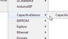
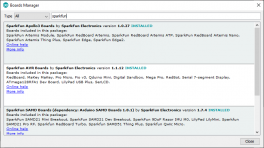
The Simple Field Oriented Control Library can be installed from the library manager in the Arduino IDE.

SimpleFOClibrary in the library manager of the Arduino IDE.
Arduino IDE (v1.x.x)
In the Arduino IDE v1.x.x, the library manager will have the following appearance for the SimpleFOC library:

This library utilizes a motor control scheme called field oriented control (FOC), which can utilize a feedback control loop to drive a motor with a higher power efficiency and precision characteristics, like evenly distributed torque control.
Info
For more details about the library, check out the online documentation.
Supported Hardware
For a detailed and up-to-date list of the hardware supported by this library, check out the library's documentation. The following are excerpts taken from the library's documentation page:
Supported microcontrollers
Choosing the Right Microcontroller
There are three main parameters when choosing the microcontroller for your project:
- Processing power (clock speed, architecture, etc.) - this will determine the performance of the FOC algorithm and the maximum speed of your motor.
- PWM generation capabilities - this will determine the number of motors you can control and the control modes you can use.
- ADC sensing capabilities - this will determine the current sensing options you have for your project.
1. Processing power
When it comes to the processing power, the rule of thumb is:
- The higher the clock speed the better.
- Aim for the FOC execution time of loopFOC() to be above 1kHz (ideally above 5kHz) depending on the motor and sensor combination you are using.
Info
For more details, please refer to the SimpleFOC Arduino library documentation.
Arduino SimpleFOClibrary has a goal to support as many BLDC and stepper motor drivers as possible. Till this moment there are two kinds of motor drivers supported by this library:
- BLDC motor driver
- 3 PWM signals ( 3 phase )
- 6 PWM signals ( 3 phase )
Current Limitations
Choosing the Appropriate Driver
Selecting the right hardware is a balance of motor type, power requirements, and the level of control precision you need.
1. Motor Type
- BLDC Motors: Requires a BLDC driver. Ensure the current and voltage ratings match your motor's specs.
⚠️ No Drone ESCs Traditional drone ESCs are not suitable for FOC because they typically use a fixed commutation scheme and lack the necessary control interfaces.
- Stepper Motors:
- Dedicated Stepper Driver: Best for 2-phase motors within standard current ranges (ex.NEMA17)
- Hybrid Mode: You can actually use any BLDC driver to run a stepper motor. - See example
⚠️ No Step/Dir Drivers Traditional "EasyDrivers" or A4988s (in step/dir mode) cannot be used for FOC because they do not allow direct phase voltage control.
2. Current Requirements
- Low Current (< 5A): Integrated driver ICs are cost-effective and easy to use.
- Examples: L6234, DRV8313, DRV8316.
- High Current (> 5A): Requires discrete MOSFET-based designs with robust thermal management (heatsinks/fans).
- Examples: DRV8302, VESC-based hardware.
- Rule of Thumb: Always select a driver with a current rating at least 20-30% higher than your motor's expected continuous current.
📢 Critical: Read before powering up!
Before running any motor, you must ensure your hardware can handle the stall current. FOC can easily pull more current than a driver can handle if not limited in software.
The Worst-Case Calculation Check your motor's phase resistance ($\(R\)\() and your power supply voltage (\)\(V_{DC}\)\(). The maximum possible current (\)\(I_{max}\)$) is:
Safety Steps:
- Compare: If $\(I_{max}\)$ exceeds your driver's rating, you must limit the voltage in software.
- Software Limit: Use driver.voltage_limit and (motor.voltage_limit and/or motor.current_limit) to stay within safe bounds. - see motor docs
- Power Supply: If you can, use a current-limited lab bench power supply for your initial tests.
Tip
While the TMC6300 isn't directly listed as part of the supported hardware for the SimpleFOC Arduino library, we have verified that is compatible with the library.
Info
For more details, please refer to the SimpleFOC Arduino library documentation.
Arduino SimpleFOClibrary supports two types of BLDC motors:
-
BLDC motors
-
3 phase (3 wire):
Gimbal Motors
Gimbal motors
Gimbal motors will work basically with any BLDC motor driver, but since the high-performance drivers have current measurement circuits optimized for high currents you will not have any benefit of using them. Therefore low-power BLDC motor drivers will have comparable performance as the expensive high-power, high-performance drivers for gimbal motors. What is in my opinion very cool! 😃 This was one of the main motivations to start developing SimpleFOCShield.
Some of the characteristics of Gimbal motors are: - High torque on low velocities - Very smooth operation - Internal resistance >10Ω - Currents up to 5A
High-performance Motors
-
-
Stepper motors
- 2 phase (4 wire)
Current Limitations
Before running any motor, you must ensure your hardware can handle the stall current. FOC can easily pull more current than a driver can handle if not limited in software.
The Worst-Case Calculation Check your motor's phase resistance ($\(R\)\() and your power supply voltage (\)\(V_{DC}\)\(). The maximum possible current (\)\(I_{max}\)$) is:
Safety Steps:
- Compare: If $\(I_{max}\)$ exceeds your driver's rating, you must limit the voltage in software.
- Software Limit: Use driver.voltage_limit and (motor.voltage_limit and/or motor.current_limit) to stay within safe bounds. - see motor docs
- Power Supply: If you can, use a current-limited lab bench power supply for your initial tests.
Info
For more details, please refer to the SimpleFOC Arduino library documentation.
6PWM Motor Driver
Users will need to utilize the BLDCDriver6PWM class to provide the six PWM signals required for the TMC6300 motor driver.
BLDCDriver6PWM-
This class provides an abstraction layer for most of the common BLDC drivers, which require six PWM signals. This method offers more control than a three PWM motor drivers, since each of the 6 half-bridges MOSFETs can be controlled independently.

