Hardware Assembly
General Connection
For a connection between two UART interfaces, the data and flow-control signals are cross-coupled. In addition, power must also be supplied to the BlueSMiRF v2.
| Device 1 | RX |
TX |
|---|---|---|
| Device 2 | TX |
RX |
UART data bus only
| Device 1 | RX |
TX |
CTS |
RTS |
|---|---|---|---|---|
| Device 2 | TX |
RX |
RTS |
CTS |
UART with flow control
JST Connector
In most circumstances, users will utilize the JST connector to interface with one of our high-precision GNSS breakout boards for RTK correction data. However, users can also use the JST breadboard cable to connect the BlueSMiRF v2 - JST to other boards.
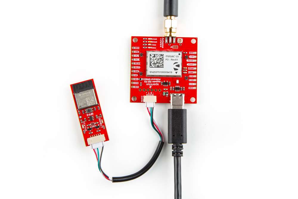
Connecting to an All-band GNSS RTK board with a JST adapter cable.
Compatibility - JST Connections
The simplest way to connect the BlueSMiRF to most of our GNSS breakout boards, is with our JST adapter cables:
Unfortunately, when we designed some of our earlier GNSS boards/products, the pin layout of the JST connection wasn't been standardized yet. Therefore, users will need to verify that the pin layout of the GNSS breakout board's JST connector is compatibile with our adapter cables.
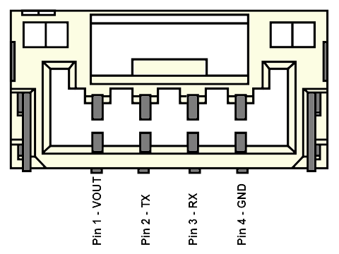
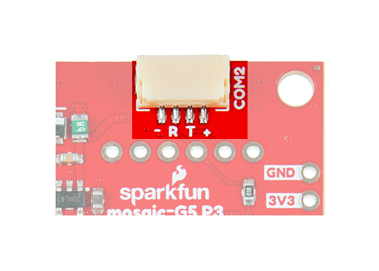
| Pin Number | 1(Left) | 2
| 3
| 4(Right) |
|---|---|---|---|---|
| Label | +, V, etc. |
T, TX, etc. |
R, RX, etc. |
-, G, etc. |
| Function | Voltage Output 3.3 to 5V |
UART Transmit |
UART Receive |
Ground |
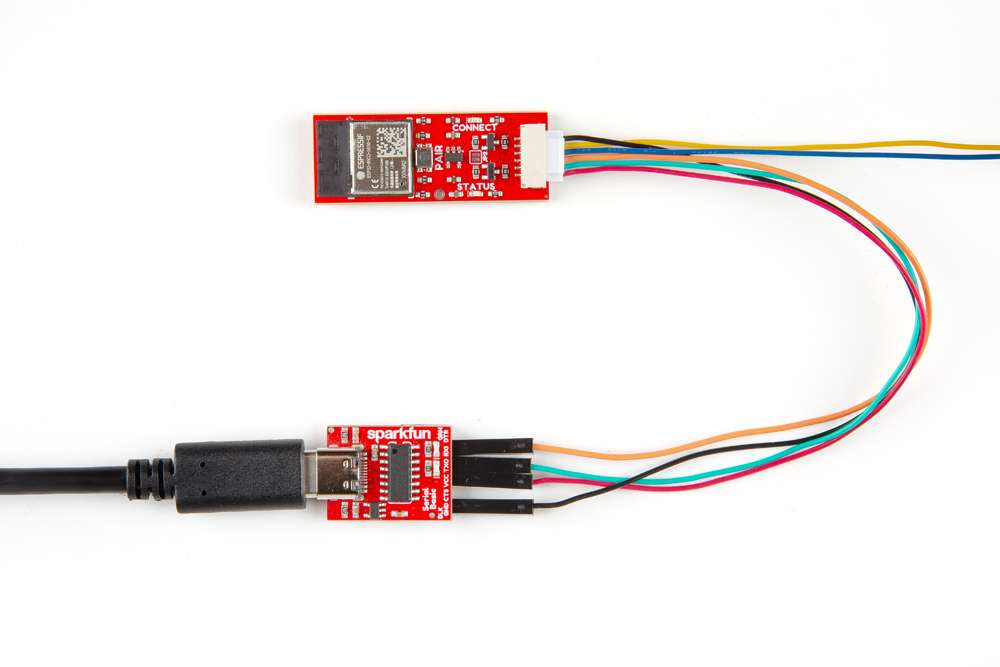
Connecting to the Serial Basic breakout with a JST breadboard cable.
Pin Layout - BlueSMiRF
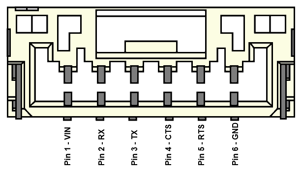
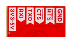
| Pin Number | 1(Left) |
2 |
3 |
4 |
5 |
6(Right) |
|---|---|---|---|---|---|---|
| Label | 3V3-5V |
RXI |
TXO |
CTS |
RTS |
GND |
| Function |
Voltage Input 3.3 to 5V |
UART Receive |
UART Transmit |
Flow Control Clear-to-Send |
Flow Control Ready-to-Send |
Ground |
Male Header Pins
The pins of the BlueSMiRF v2 - Male Header are broken out into 0.1"-spaced male header pins on the outer edges of the board. In most circumstances, users will simply connect the BlueSMiRF v2 to the female headers of another board or utilize jumper wires to make the connection.
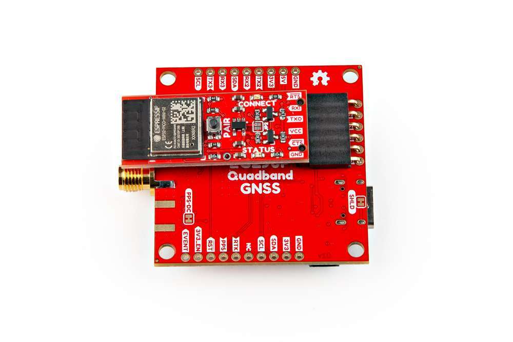
Connecting to a header on the All-band GNSS RTK breakout board.
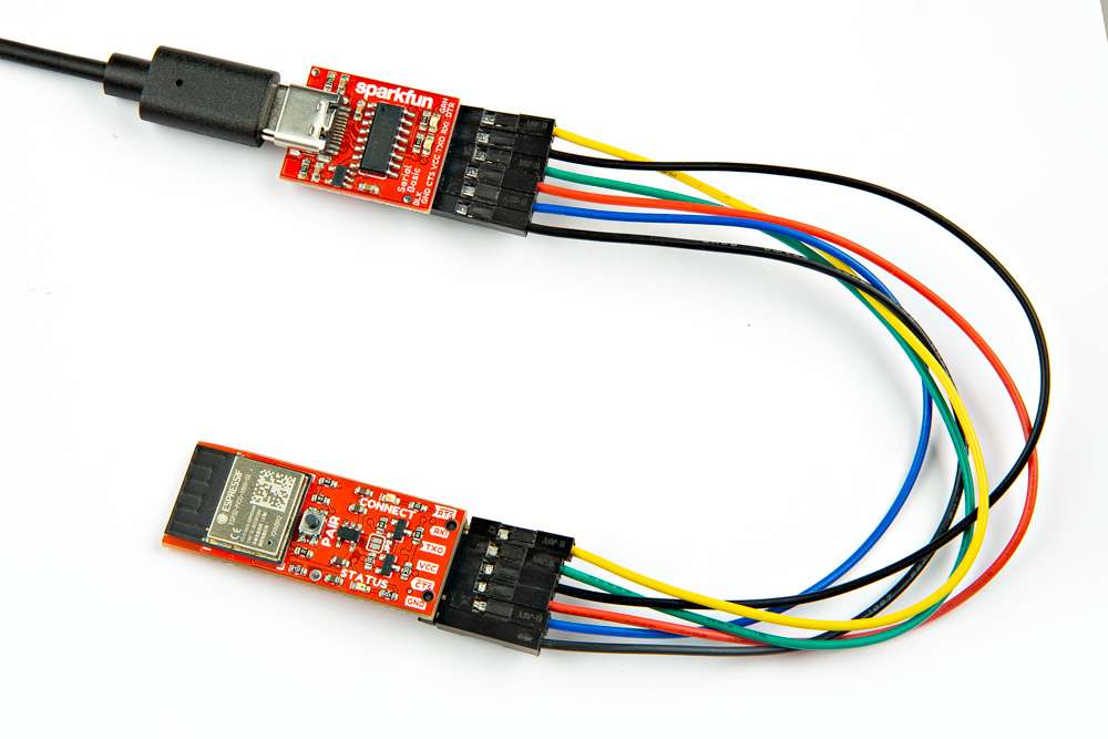
Connecting to the Serial Basic breakout with jumper wires.
Pin Layout - BlueSMiRF
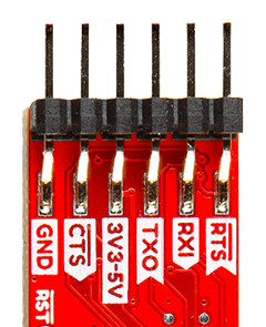
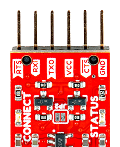
| Pin Number | 1(Left) |
2 |
3 |
4 |
5 |
6(Right) |
|---|---|---|---|---|---|---|
| Label | GND |
CTS |
Top: VCCBottom: 3V3-5V |
TXO |
RXI |
RTS |
| Function | Ground | Flow Control Clear-to-Send |
Voltage Input 3.3 to 5V |
UART Transmit |
UART Receive |
Flow Control Ready-to-Send |
PTH Pads
The PTH pads of the BlueSMiRF v2 - PTH Pins are broken out into 0.1"-spaced holes on the outer edges of the board.
New to soldering?
If you have never soldered before or need a quick refresher, check out our How to Solder: Through-Hole Soldering guide.
-
How to Solder: Through-Hole Soldering
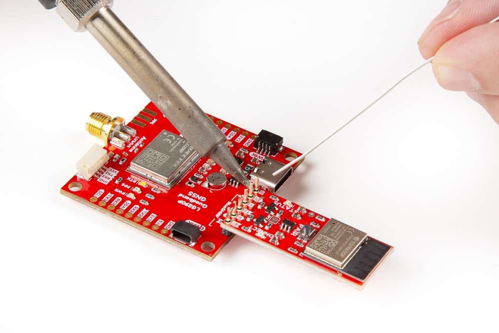
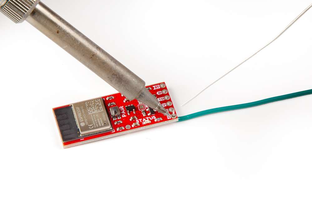
Pin Layout - BlueSMiRF
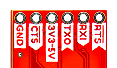
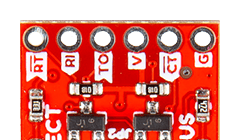
| Pin Number | 1(Left) |
2 |
3 |
4 |
5 |
6(Right) |
|---|---|---|---|---|---|---|
| Label | Top: GBottom: GND |
Top: CTBottom: CTS |
Top: VBottom: 3V3-5V |
Top: TOBottom: TXO |
Top: RIBottom: RXI |
Top: RTBottom: RTS |
| Function | Ground | Flow Control Clear-to-Send |
Voltage Input 3.3 to 5V |
UART Transmit |
UART Receive |
Flow Control Ready-to-Send |