Hardware Overview
What's New?
The design of the BlueSMiRF is similar to previous generations. However, we have made a few design improvements that users will appreciate. In testing, we got about ~110 feet (~33m) of range from a pair of BlueSMiRF v2s in the SparkFun building.
- Features an ESP32-PICO-MINI-02 module programmed with our open-source firmware
- Easily update the firmware Over-the-Air or through the serial interface
- Configure the settings with AT-commands
- A user button has been added to simplify pairing, triggering various modes of operation, and resetting the factory defaults
- We manufacture three variants, with different connections to simplify hooking up the BlueSMiRF to your project
- PTH pad and male header variants, which now have pin labels on both sides of the boards
- JST variant that is easily connected to our high-precision GNSS breakout boards
Info
For a full background on the development and design revisions of the BlueSMiRF, check out the Board Revision History page of this guide.
Board Layout
The SparkFun BlueSMiRF v2 features the following:
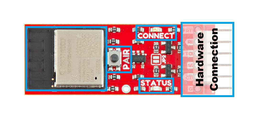
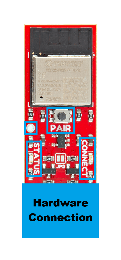
The primary features of the BlueSMiRF v2 boards.
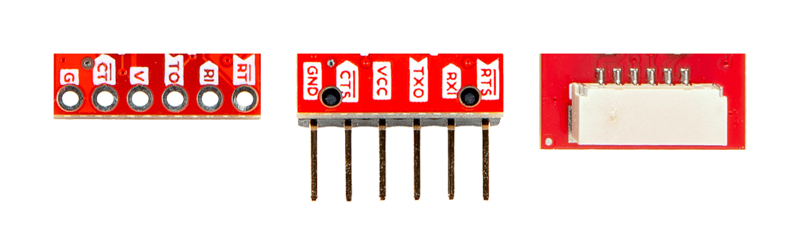
The connection options for the BlueSMiRF v2: (from left; to right)
PTH pads, male header pins, or JST-GH connector
-
- ESP32 Module
- Espressif's ESP32-PICO-MINI-02 module
-
- PAIR Button
- A multi-use button that changes between the various modes of operation.
-
- Status LEDs
- The green
CONNECTand redSTATUSLEDs are used to indicate various modes of operation.
-
- Hardware Connection
- This connection breaks out the pins for the UART interface and power supply for the BlueSMiRF. Additionally, the three variants provide different options for connecting the BlueSMiRF to their project.
-
Design Files
- Schematics
- KiCad Files
- Board Dimensions
- PTH Pads:
- 1.50" x 0.60" (38.1mm x 15.2mm)
- Male Header:
- 1.74" x 0.60" (44.2mm x 15.2mm)
- JST Connector:
- 1.60" x 0.60" (40.8mm x 15.2mm)
- PTH Pads:
- STEP Files
-
How-to Manipulate 3D Model
Controls Mouse Touchscreen Zoom Scroll Wheel 2-Finger Pinch Rotate Left-Click & Drag 1-Finger Drag Move/Translate Right-Click & Drag 2-Finger Drag
Board Dimensions
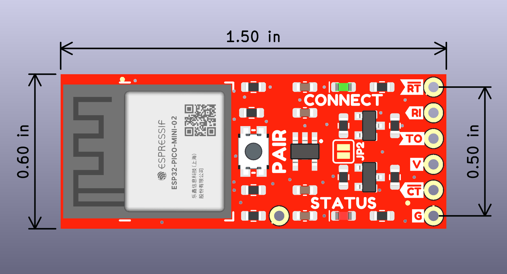
Dimensions of the BlueSMiRF v2 - PTH.
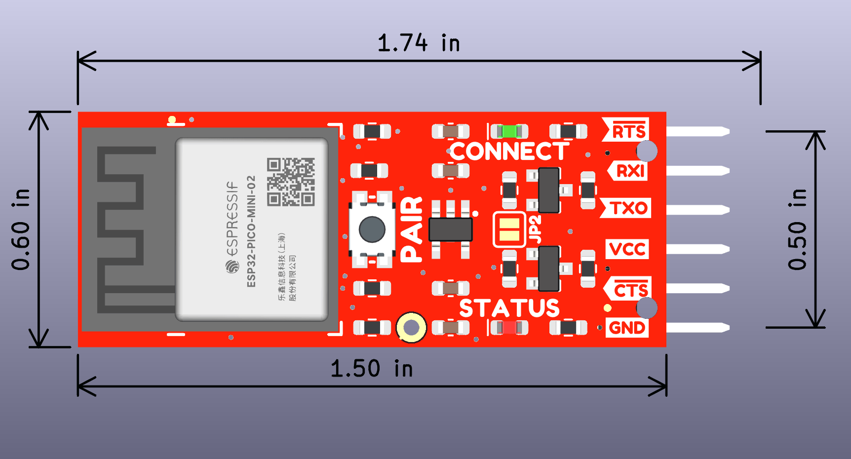
Dimensions of the BlueSMiRF v2 - Header.
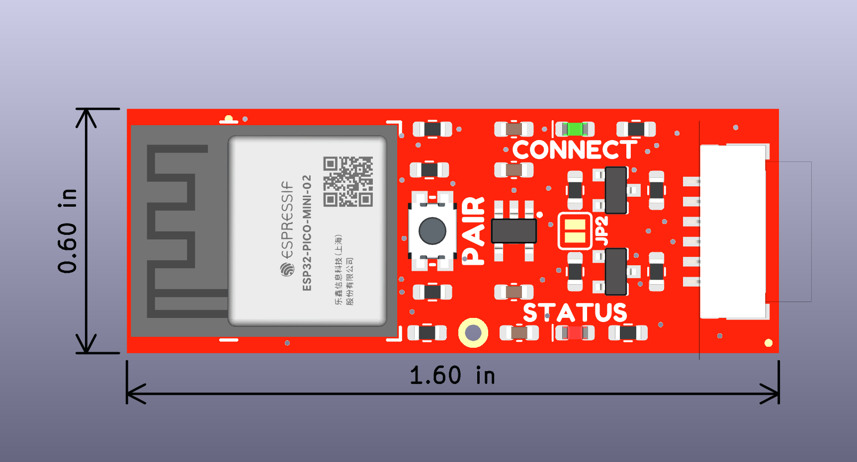
Dimensions of the BlueSMiRF v2 - JST.
Need More Dimensions?
For more board dimensions, users can download the KiCad files for these board. These files can be opened in KiCad and measurements can be made with the measuring tool.
KiCad - Free Download!
KiCad is free, open-source CAD program for electronics. Click on the button below to download their software. (*Users can find out more information about KiCad from their website.)
 Measuring Tool
This video demonstrates how to utilize the dimensions tool in KiCad, to include additional measurements:

ESP32 Pico-Mini
The brains of the BlueSMiRF v2 is an ESP32 Pico-Mini module. The Espressif series of ESP32 modules are a versatile, compact MCU modules with WiFi, BT, and BLE capabilities that target a wide variety of applications. At the core of the ESP32 Pico-Mini module is the ESP32-PICO-V3-02, a System-in-Package device, along with an integrated 8 MB SPI flash, 2 MB SPI PSRAM, and 40 MHz oscillator. While the ESP32 Pico-Mini module has twenty-seven multifunctional GPIO that are available, only seven of I/O pins are actually utilized on the BlueSMiRF v2.
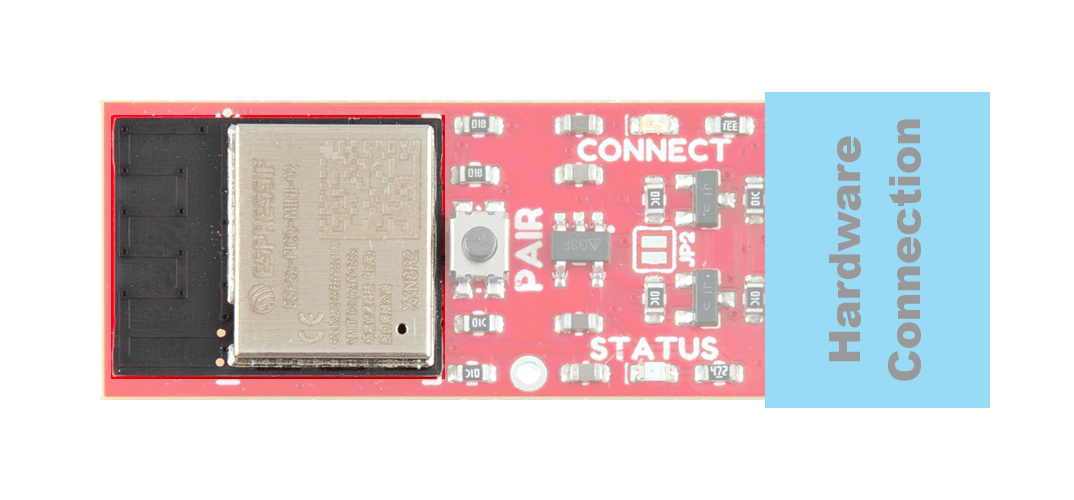
The ESP32 PICO-MINI-02 module on the BlueSMiRF v2.
Note
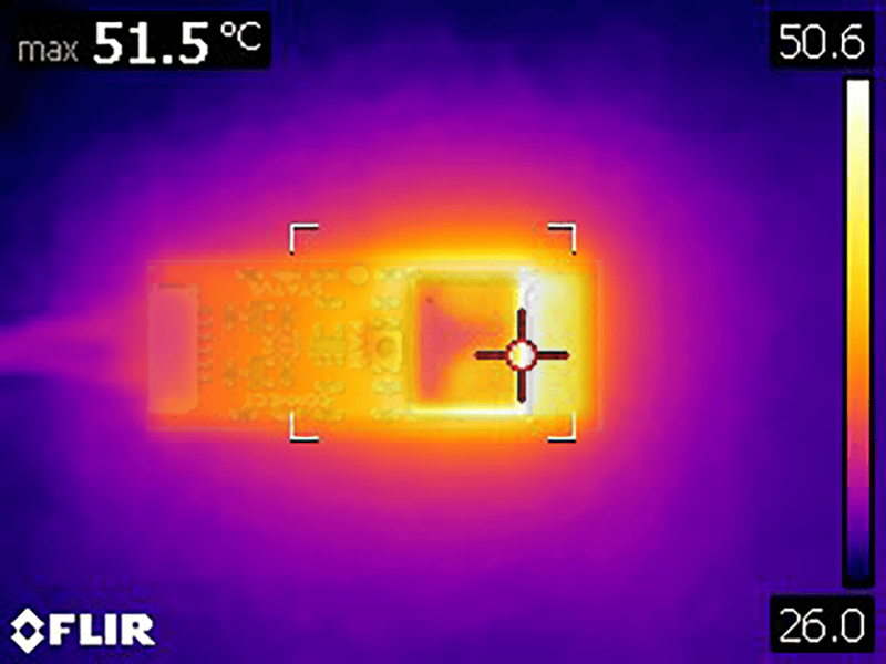
The ESP32 module can get a little warm when operating; don't be alarmed, this is just heat dissipating from the internal components.
General Features
Features
- Electrical Characteristics:
- Operating Voltage: 3.0 - 3.6V
- Current Consumption:
- RF Operation: 368mA (peak)
- Normal Operation: 20-31mA
- Light-Sleep: 0.8mA
- Deep-Sleep: 5µA
- Xtensa® Dual-Core 32-bit LX6 Microprocessor (up to 240MHz)
- 448KB of ROM and 520KB SRAM
- 8MB SPI Flash
- 2MB PSRAM
- 16KB SRAM in RTC
- Operating Temperature: -40 to 85°C
- PCB antenna
- WiF 802.11b/g/n
- Bit Rate: up to 150Mbps (802.11n)
- Frequency Range: 2412 - 2484MHz
- Bluetooth
- Bluetooth v4.2 Specification:
- BR/EDR
- Bluetooth LE
- Transmitter Class: 1, 2, and 3
- Bluetooth v4.2 Specification:
- 27 GPIO (including strapping pins)
- Other Supported Peripherals:
- SD card, SDIO, I2S, IR, pulse counter, TWAI/CAN, Ethernet MAC
With the pin multiplexing capabilities of the ESP32 SoC, various pins can have several functionalities. For more technical specifications on the I/O pins, please refer to the ESP32 SoC datasheet.
- 18x 12-bit analog to digital converter (ADC) channels
- 3x UARTs (only two are configured by default in the Arduino IDE, one UART is used for bootloading/debug)
- 3x SPI (only one is configured by default in the Arduino IDE)
- 2x I2C (only one is configured by default in the Arduino IDE)
- 2x digital-to-analog converter (DAC) channels
- 16x 20-bit PWM outputs
- 10x Capacitive Touch Inputs
Warning
Users should be aware of the following nuances of the ESP32 Pico-Mini module:
- All the GPIO are 3.3V pins.
- The I/O pins are not 5V-tolerant! To interface with higher voltage components, a logic level adapter is recommended.
- The ESP32 Pico-Mini is only compatible with 2.4GHz WiFi networks; it will not work on the 5GHz bands.
- There are electrical limitations to the amount of current that the ESP32 Pico-Mini module can sink or source. For more details, check out the ESP32 Pico-Mini module datasheet.
- There are some limitations to the ADC performance, see the Note from the ADC Characteristics section of the ESP32 SoC datasheet.
- For details on the boot mode configuration, please refer to section 3.3 Strapping Pins of the ESP32 SoC datasheet.
Power Modes
The ESP32 Pico-Mini module has various power modes:
- Active - The chip radio is powered on. The chip can receive, transmit, or listen.
- Modem Sleep - The CPU is operational and the clock is configurable. The Wi-Fi/Bluetooth baseband and radio are disabled.
- Light Sleep - The CPU is paused. The RTC memory and RTC peripherals, as well as the ULP coprocessor are running.
- Deep Sleep - Only the RTC memory and RTC peripherals are powered on. The ULP coprocessor is functional.
- Hibernation - Only one RTC timer on the slow clock and certain RTC GPIO active.
- Off - Chip is powered off.
For more information on the power management of the ESP32 Pico-Mini module, pleaser refer to Section 4.4 and Tables: 8 and 9 of the ESP32 Pico-Mini module datasheet.
Pin Connections
Pin Connections
The ESP32 Pico-Mini module features twenty-seven multifunctional GPIO pins; however, only seven of I/O pins* are actually utilized for the BlueSMiRF v2.
| ESP32 Pins | BlueSMiRF |
|---|---|
EN |
RST PTH Pad |
GPIO 0 |
Pair Button |
GPIO 1 |
TX Pin |
GPIO 3 |
RX Pin |
GPIO 8 |
STATUS LED |
GPIO 13 |
CONNECT LED |
GPIO 15 |
Disables Debug |
GPIO 19 |
CTS Pin |
GPIO 22 |
RTS Pin |
Firmware
Firmware
The BlueSMiRF v2 comes pre-programmed with the latest version of our open-source firmware. However, users are free to modify the firmware and/or reprogram their board for their purposes.
Our firmware provides short-range, point-to-point communication; allowing serial UART data to be transmitted between two Bluetooth devices. It includes support for both the SPP and BLE protocols and features a massive >10kB buffer for each RX and TX channel to compensate for transmission delays. The firmware also offers a set of AT-commands to configure the BlueSMiRF v2's settings: including the baud rate, flow control, LED mode, and Over-The-Air (OTA) updates over a 2.4GHz WiFi network to name a few.
- Serial Bluetooth® Point-to-Point Communication
- Bluetooth Protocols Supported
- Serial Port Profile (SPP)
- Bluetooth Low Energy (BLE)
- Firmware Over-the-Air (OTA) Updates via 2.4GHz WiFi
Bluetooth Protocols
While Bluetooth Classic (Serial Port Profile or "SPP") is the primary communication protocol, which makes it highly compatible with Android devices and most computers, the BlueSMiRF v2 also supports Bluetooth Low Energy (BLE) protocol for connecting with Apple devices and other low-power devices.
Performance
Testing a pair of BlueSMiRF v2s and we were able to achieve a range of ~110 feet (~33m) in the SparkFun building.
Bootloader Mode
Users can manually force the ESP32 into the serial bootloader mode with the PAIR button, to upload new firmware to the BlueSMiRF v2. Please, refer to the PAIR Button section below for more information.
Programming the ESP32 in Arduino
To program the ESP32 Pico-Mini module in the Arduino IDE, users should select the ESP32 > ESP32 Dev Module from the Board Manager list. Users should also be aware that not all of the capabilities, listed above, are available in the Arduino IDE; the Espressif IDF should be utilized for the full capabilities of the ESP32. When programming the module with the Arduino IDE, only the following peripherals are supported:
- Only two UART interfaces are available.
- Only one SPI bus is defined.
- Only one I2C bus is defined.
For more technical specifications on the I/O pins, you can refer to the schematics, ESP32 Pico-Mini module datasheet, ESP32 SoC datasheet, and documentation for the ESP32 Arduino core.
Any of the GPIO pins of the ESP32 module can function as digital pins. In the Arduino IDE, users will need to declare the pinMode() function for the pins used in this manner, in the setup of their sketch.
-
Input
When configured properly, an input pin will be looking for a
HIGHorLOWstate. This functionality is accessed in the Arduino IDE using thedigitalRead(pin)function. By default, in the Arduino IDE,digitalRead()returns a boolean value. Input pins are high impedance and takes very little current to move the input pin from one state to another. -
Output
When configured as an output the pin will be at a
HIGHorLOWvoltage. This functionality is accessed in the Arduino IDE using thedigitalWrite(pin, value)function. Output pins are low impedance; this means that they can provide a relatively substantial amount of current to other circuits.
The ESP32 module provides a 12-bit ADC (Analog Digital Converters) input on eighteen of its I/O pins. This functionality is accessed in the Arduino IDE using the analogRead(pin) function. By default, in the Arduino IDE, analogRead() returns a 10-bit value. To change the resolution of the value returned by the analogRead() function, use the analogReadResolution(bits) function.
The ESP32 module supports up to sixteen channels of 20-bit PWM (Pulse Width Modulation) outputs on any of its I/O pins. This is accessed in the Arduino IDE using the analogWrite(pin, value) function. By default, in the Arduino IDE, analogWrite() accepts an 8-bit value. To change the resolution of the PWM signal for the analogWrite() function, use the analogWriteResolution(bits) function.
The ESP32 module supports up to two 8-bit DAC (Digital Analog Converters) outputs. This is accessed in the Arduino IDE using the dacWrite(pin, value); function. By default, in the Arduino IDE, the ESP32 Dev Module board definition supports:
| DAC1 | GPIO 25 |
|---|---|
| DAC2 | GPIO 26 |
The ESP32 module provides three UART ports. By default, the UART ports for Serial and Serial1 can be accessed through the Arduino IDE using the serial communication class. By default, in the Arduino IDE, the ESP32 Dev Module board definition supports:
-
SerialUART Port
RX0 GPIO 1TX0 GPIO 3 -
Serial1UART Port
RX1 GPIO 21TX1 GPIO 22
Tip
We have noticed that with the ESP32 Arduino core, Serial.available() does not operate instantaneously. This is due to an interrupt triggered by the UART, to empty the FIFO when the RX pin is inactive for two byte periods:
-
At 9600 baud,
hwAvailabletakes about 11 ms before the UART indicates that data was received from:\r\nERROR\r\n.\[ (bytes + 2) * 1ms = 11ms \] -
At 115200 baud,
hwAvailabletakes about 1 ms before the UART indicates that data was received from:\r\nERROR\r\n.\[ (bytes + 2) * .087ms = 1ms \]
For more information, please refer to this chatroom discussion.
The ESP32 module provides three SPI buses. By default, in the Arduino IDE, the SPI class is configured to utilize pins GPIO 32 (SCK), GPIO 25 (POCI), GPIO 26 (PICO), and GPIO 27 (SS) for its chip select. In order to utilize the other SPI ports or objects, users will need to create a custom SPI object and declare which pins to access. By default, in the Arduino IDE, the ESP32 Dev Module board definition supports:
| SCK | GPIO 32 (SCK) |
|---|---|
| SDI or POCI | GPIO 25 (MISO) |
| SDO or PICO | GPIO 26 (MOSI) |
| CS* | GPIO 27 (SS) |
Signal Nomenclature
To comply with the latest OSHW design practices, we have adopted the new SPI signal nomenclature (SDO/SDI and PICO/POCI). The terms Master and Slave are now referred to as Controller and Peripheral. The MOSI signal on a controller has been replaced with SDO or PICO. Please refer to this announcement on the decision to deprecate the MOSI/MISO terminology and transition to the SDO/SDI naming convention.
The ESP32 module module can support up to two I2C buses. By default, in the Arduino IDE, the Wire class is configured to utilize pins GPIO 20 (SDA) and GPIO 7 (SCL). In order to utilize another I2C port, users will need to create a custom Wire object and declare which pins to access. By default, in the Arduino IDE, the ESP32 Dev Module board definition supports:
| SCL0 | GPIO 7 (SCL) |
|---|---|
| SDA0 | GPIO 20 (SDA) |
Hardware Connection
Each variant of the BlueSMiRF v2, has a different hardware connection option. Users can purchase a board variant with either PTH pads, male header pins, or JST-GH connector to suite their needs.
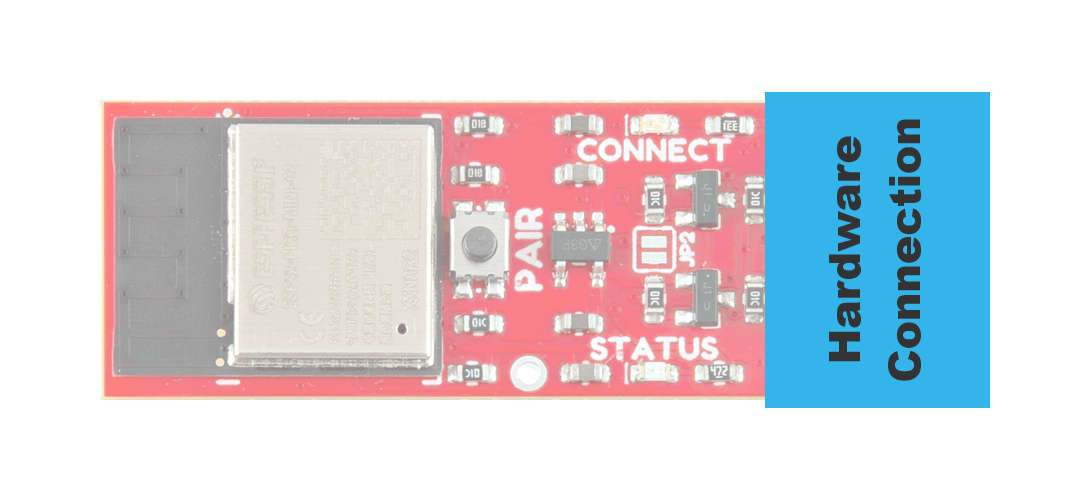
The hardware connection on the BlueSMiRF v2.
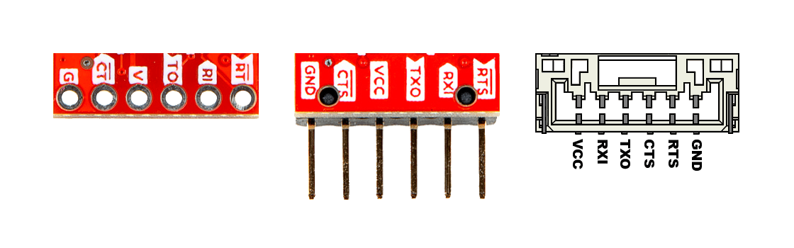
The connection options for the board variants: (from left; to right)
PTH pads, male header pins, or JST-GH connector.
The pin layout for these connections, are summarized in the table below. The pin numbers are ordered from left-to-right, as viewed from the side facing the connection.
| Connection Type | 1(Left) |
2 |
3 |
4 |
5 |
6(Right) |
|---|---|---|---|---|---|---|
| PTH Pads Male Header Pins |
GND |
CTS |
VCC |
TXO |
RXI |
RTS |
| JST Connector | VCC |
RXI |
TXO |
CTS |
RTS |
GND |
Backwards Compatibility
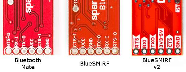
The pin layout of the BlueSMiRF v2 variants with the PTH pads and male header pins, will only be backwards compatible with previous versions of the BlueSMiRF Mate, as shown in the image below.
Power Pins
The BlueSMiRF v2 only requires 3.3V and is powered through the VCC and GND pins of its hardware connection.
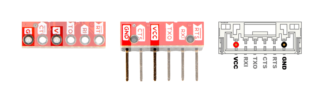
The power pins from the BlueSMiRF v2's hardware connection.
Below, is a general summary of the power circuitry:
VCC- The input voltage for the BlueSMiRF v2, provided from its hardware connection- Supplies the AP2112 LDO regulator
- Input Voltage Range: 3.3 to 6.0V (1)
- Powers the ESP32 module, LEDs, and lower voltage of the logic-level shifters
- The voltage regulator can be bypassed with the
JP2jumper
- Supplies the AP2112 LDO regulator
GND- The common ground or the 0V reference for the voltage supplies.
- While the input voltage range for the AP2112 LDO voltage regulator is 2.5 to 6.0V, we recommend a minimum input voltage of 3.3V to prevent the ESP32 module browning out.
Power Consumption
The board's power consumption is based on its operation. Here are some of estimates based on our measurements at 3.3V.
- Idle: 72mA / 238mW
- Connected with No Traffic: 75mA / 248mW
- Connected with Duplex Traffic: 140mA / 462mW
Info
For more details, users can reference the schematics and the datasheets of the individual components on the board.
UART Interface
The UART interface provides access to the primary function of the BlueSMiRF v2. It supports full-duplex data transmission for baud rates ranging between 2400-921600bps.
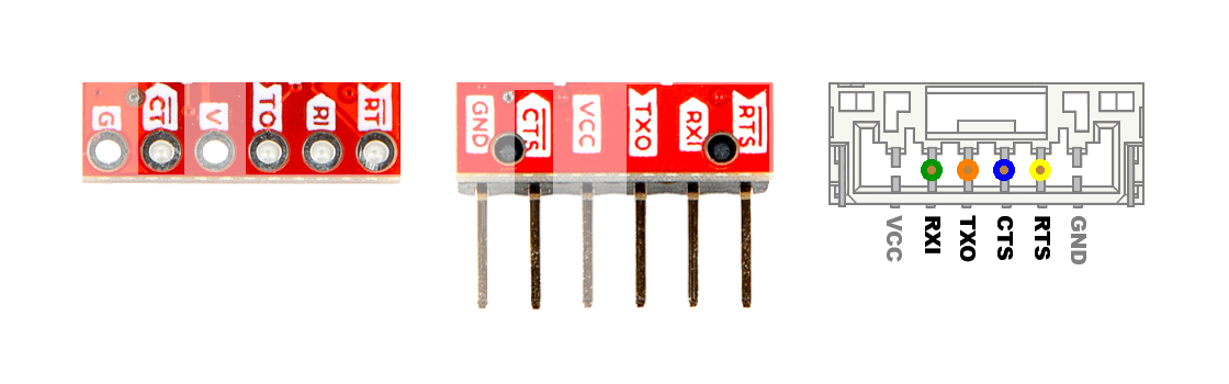
The pins of the UART interface for the BlueSMiRF v2.
| Device 1 | RX |
TX |
CTS |
RTS |
|---|---|---|---|---|
| Device 2 | TX |
RX |
RTS |
CTS |
The UART signals cross-coupled between two devices
Below, is a general summary of the UART interface:
-
Data Bus
- Features logic-level converters; the higher voltage is supplied by
VCC - Full-duplex support (simultaneous/bidirectional communication)
RXI- Data input to the BlueSMiRF v2 from its hardware connection- If connected, data received from the
RXIpin is piped to its Bluetooth connection - Buffer Size: 51kB
- If connected, data received from the
TXO- Data output from the BlueSMiRF v2 to its hardware connection- If connected, data received from the Bluetooth connection is piped to its
TXOpin - Buffer Size: 10kB
- If connected, data received from the Bluetooth connection is piped to its
Info
By default, the baud rate is configured to 115200bps. Use the
AT-SerialSpeedcommand to change this setting. - Features logic-level converters; the higher voltage is supplied by
-
Flow Control (Optional)
- Direct connection to GPIO; no logic-level conversion
- Does not support legacy hardware flow control for DTE (Data Terminal Equipment) and DCE (Data Communications Equipment)
CTS- Connected device, controls data transmission from BlueSMiRF v2HIGH: Connected device, signaling that it is ready for data to be sentLOW: Connected device, signaling that the data transmission needs to be halted
RTS- Controls data transmission to the BlueSMiRF v2HIGH: BlueSMiRF v2 is ready for data to be transmitted to itLOW: BlueSMiRF v2 buffer is full; assertsLOWto halt data transmission
Info
By default, the flow control pins are disabled in the firmware. Use the
AT-FlowControl=1command to enable them.Tip
The flow control pins aren't necessary for the BlueSMiRF v2 to function. However, when enabled, it assists with buffer control, device latency, and data synchronization.
Tip
These data bus and flow control signals need to be cross-coupled between the two devices.
Pair Button
The PAIR button is used to switch between the various modes of operation for the BlueSMiRF v2. It is used to simplify pairing, triggering various modes of operation, and restoring the settings to their factory defaults.
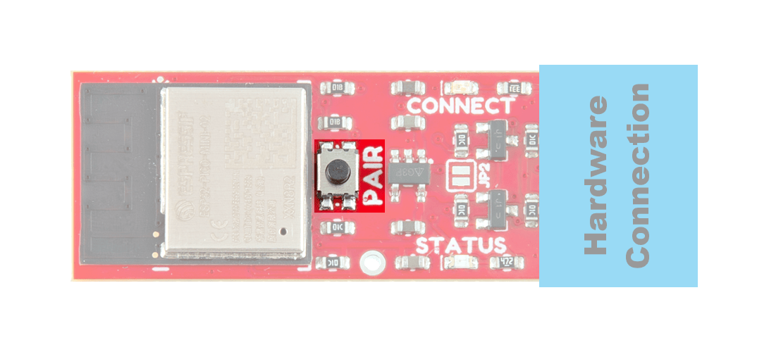
PAIR Button on the BlueSMiRF v2.
- Discoverable Mode
- A default state, where the
STATUSLED will fade in-and-out a few times to indicate the device is ready to be paired with a Bluetooth device.
- A default state, where the
- BlueSMiRF Pairing Mode
- Used to pair the BlueSMiRF v2 with another BlueSMiRF v2 in the (default) discoverable mode.
- Press and hold the PAIR button down for 4 - 8sec, the
CONNECTandSTATUSLED will blink back-and-forth.- If the PAIR button is continued to be held, the device will transition to a factory reset (see below).
- If the BlueSMiRF v2 hasn't been discovered or paired with the other BlueSMiRF v2 after a few seconds, it will return to the (default) discoverable mode and the
STATUSLED will fade in-and-out a few times to indicate the transition.
- Bootloader Mode
- Used to manually update the firmware through the UART interface.
- To enter bootloader mode, users will need to hold down the PAIR button while the BlueSMiRF v2 is not powered.
- Continue holding down the PAIR button, while applying power to put the microcontroller into bootloader mode.
- Release the button, to upload new firmware.
- Factory Reset
- Press and hold the PAIR button down for more than 8sec, the
CONNECTandSTATUSLED will blink back-and-forth, rapidly. - Once the user releases the button, the original factory settings are be applied and the BlueSMiRF v2 resets. Then, it returns to the (default) discoverable mode.
- Press and hold the PAIR button down for more than 8sec, the
LEDs
The BlueSMiRF v2 has two status LEDs, which function differently based on the Bluetooth connection and/or datastream status; in conjunction with the device's AT-LedStyle configuration setting and operation mode:
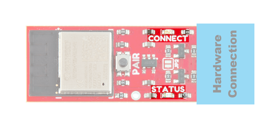
The status indication LEDs on the BlueSMiRF v2.
-
Normal Operation
Setting:
AT-LedStyle=0(Default)CONNECT- Indicates the Bluetooth connection status- Discoverable Mode: This LED will blink, while the BlueSMiRF v2 is available to be paired with.
- Active Connection: This LED will turn solid, once the BlueSMiRF v2 has an active Bluetooth connection
STATUS- Indicates the status of the UART datastream- Data Transmission: The
STATUSLED will blink, as data is sent to the BlueSMiRF v2.
- Data Transmission: The
Setting:
AT-LedStyle=1CONNECT- Indicates the Bluetooth connection status and the status of theTXOdatastream- Discoverable Mode: This LED will blink, regularly, while the BlueSMiRF v2 awaits for an active Bluetooth connection.
- Active Connection
- Initial Connection: Upon an initial connection, this LED will remain solid until data is passed through the
TXOpin of the BlueSMiRF v2. - Data Transmission: This LED will blink as data is passed through the
TXOpin of the BlueSMiRF v2.
- Initial Connection: Upon an initial connection, this LED will remain solid until data is passed through the
STATUS- Indicates the status of theRXIdatastream- Data Transmission: This LED will blink, as data is passed through the
RXIpin of the BlueSMiRF v2; regardless of the Bluetooth connection status.
- Data Transmission: This LED will blink, as data is passed through the
-
Pairing Mode
- After the PAIR button has been held down for 4-8sec, the
CONNECTandSTATUSLED will blink back-and-forth.- If the PAIR button is continued to be held, the device will transition to a factory reset (see below).
- After a few seconds in pairing mode, if the BlueSMiRF v2 hasn't been paired with, it will return to the (configured) discoverable mode and the
STATUSLED will fade in-and-out a few times to indicate the transition.
- After the PAIR button has been held down for 4-8sec, the
- Factory Reset
- After the PAIR button has been held down past 8sec sec, the
CONNECTandSTATUSLED will blink back-and-forth, rapidly. - Once the user releases the button, the original factory settings are be applied and the BlueSMiRF v2 resets. Then, it returns to the (default) discoverable mode.
- After the PAIR button has been held down past 8sec sec, the
- Command Mode
- Upon entering command mode, the
CONNECTandSTATUSLED will blink simultaneously. -
After an AT-command has been initially sent sent:
Setting:
AT-LedStyle=0(Default)The LEDs will then return to functioning in the (default) normal operation.
Setting:
AT-LedStyle=1The LEDs will continue to blink simultaneously.
- Upon entering command mode, the
Reset Pin
The reset pin for the ESP32 is connected to the RST PTH pad. Pulling this pin LOW will restart the ESP32.
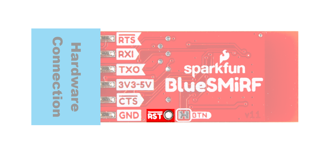
The reset PTH pad on the BlueSMiRF v2.
Tip
This is primarily provided for our production team, as a test point for programming and testing the board. However, users can use it when reprogramming the ESP32 microcontroller.
Jumpers
Never modified a jumper before?
Check out our Jumper Pads and PCB Traces tutorial for a quick introduction!
-

How to Work with Jumper Pads and PCB Traces
There are two jumpers on these board that can be used to easily modify the hardware connections.
JP2-
This jumper can be closed to bypass the 3.3V voltage regulator; directly passing power from the
VCCpin to all the components on the3V3power rail.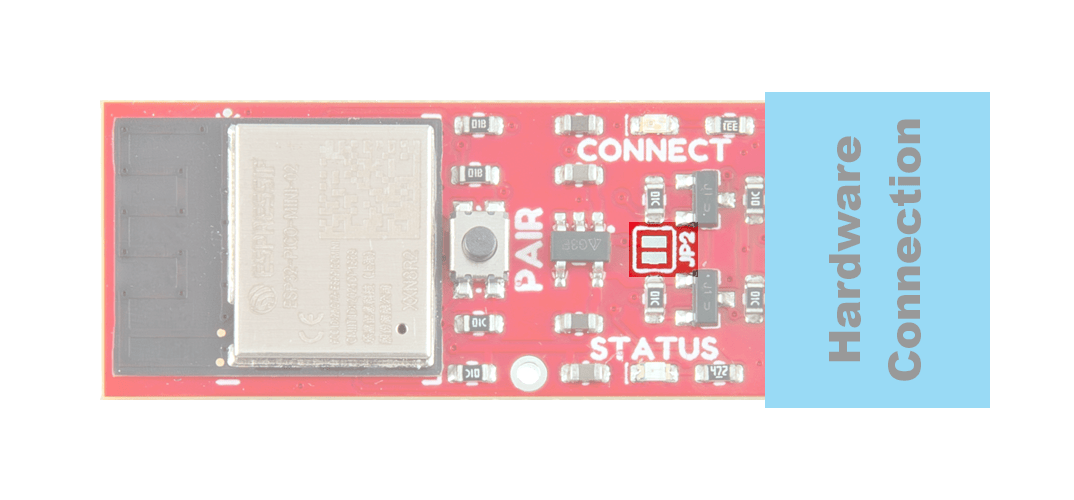
The JP2jumper on the top of the BlueSMiRF v2.Danger
Please be aware of the voltage ratings for all the components, before proceeding with this modification. Exceeding the electrical specifications of certain components will permanently damage and/or disable them.
BTN-
This jumper can be cut to disconnect the PAIR button from the
GPIO 0pin of the ESP32.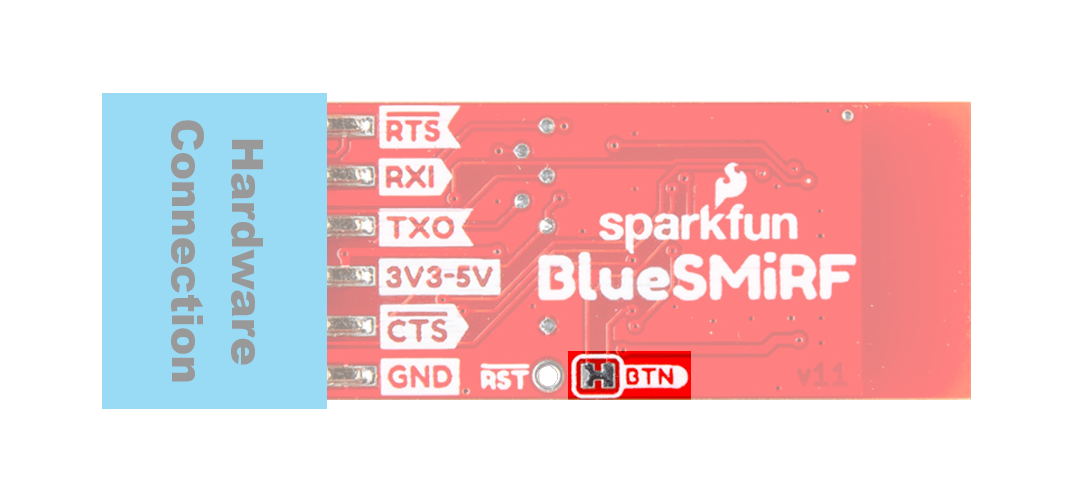
The BTNjumper on the bottom of the BlueSMiRF v2.