Introduction
The STHS34PF80 sensor, from ST Microelectronics, is designed to measure the precise black-body radiation (as described by Plank's law) of an object; as well as monitor ambient temperature conditions within its 80° field of view. The sensor is composed of a matrix of floating vacuum thermal transistors MOS split into two parts, one exposed to IR radiation and the other one shielded. The differential reading between the segments, allows the sensor to remove self-heating effects. The STHS34PF80 also incorporates algorithms to detect and discriminate between stationary and moving objects. These features enable the sensor to work as a human presence and motion sensor in different applications such as alarm systems, anti-intruder systems, smart lighting, and room occupancy.
 Purchase from SparkFun
  Purchase from SparkFun
 The sensor can operate in multiple lighting conditions and is unaffected by visible light or other bands thanks to the 5 to 20µm optical band-pass filter. The STHS34PF80 has an output data rates between 0.25 to 30 Hz and an available single-shot, which are accessed through its I²C/SPI interface. The SparkFun Qwiic Human Presence and Motion Sensor boards are available in both the standard 1"x1" Qwiic form factor and the mini breakout board. (The mini form-factor is also panel mount compatible for use in enclosures. (1))
- Please refer to the hardware implementation guidelines for the STHS34PF80 sensor.
Required Materials
To get started, users will need a few items. Now some users may already have a few of these items, feel free to modify your cart accordingly.
- Computer with an operating system (OS) that is compatible with all the software installation requirements
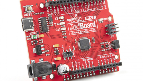
- A compatible microcontroller/Arduino board; we recommend the SparkFun RedBoard Plus.
- USB 3.1 Cable A to C - 3 Foot - Used to interface with the RedBoard Plus (1)
- SparkFun Qwiic Cable Kit (2)
- SparkFun Human Presence and Motion Sensor - STHS34PF80 (3)
- If your computer doesn't have a USB-A slot, then choose an appropriate cable or adapter.
- Check out our other Qwiic cable options.
- The mini version of this product is panel mount compatible.
-
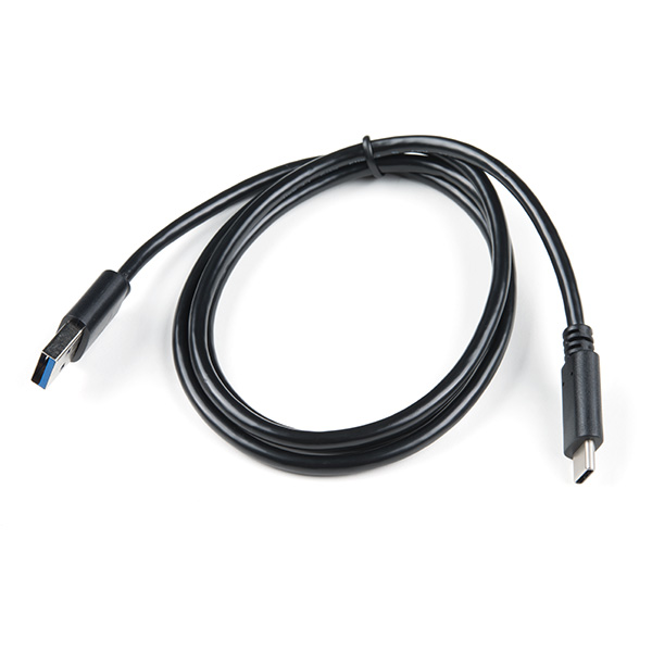
USB 3.1 Cable A to C - 3 Foot
CAB-14743 -
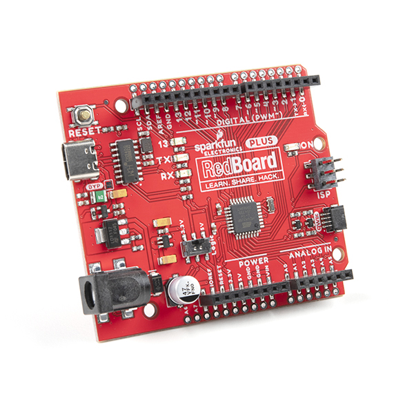
SparkFun RedBoard Plus
DEV-18158 -
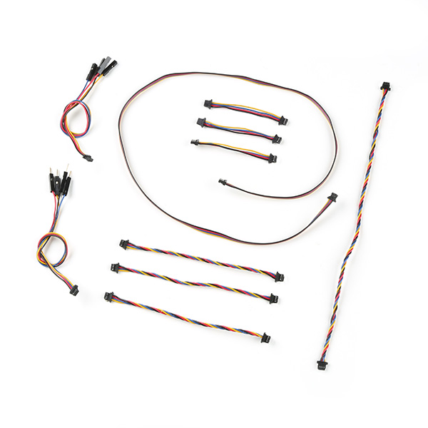
SparkFun Qwiic Cable Kit
KIT-15081 -
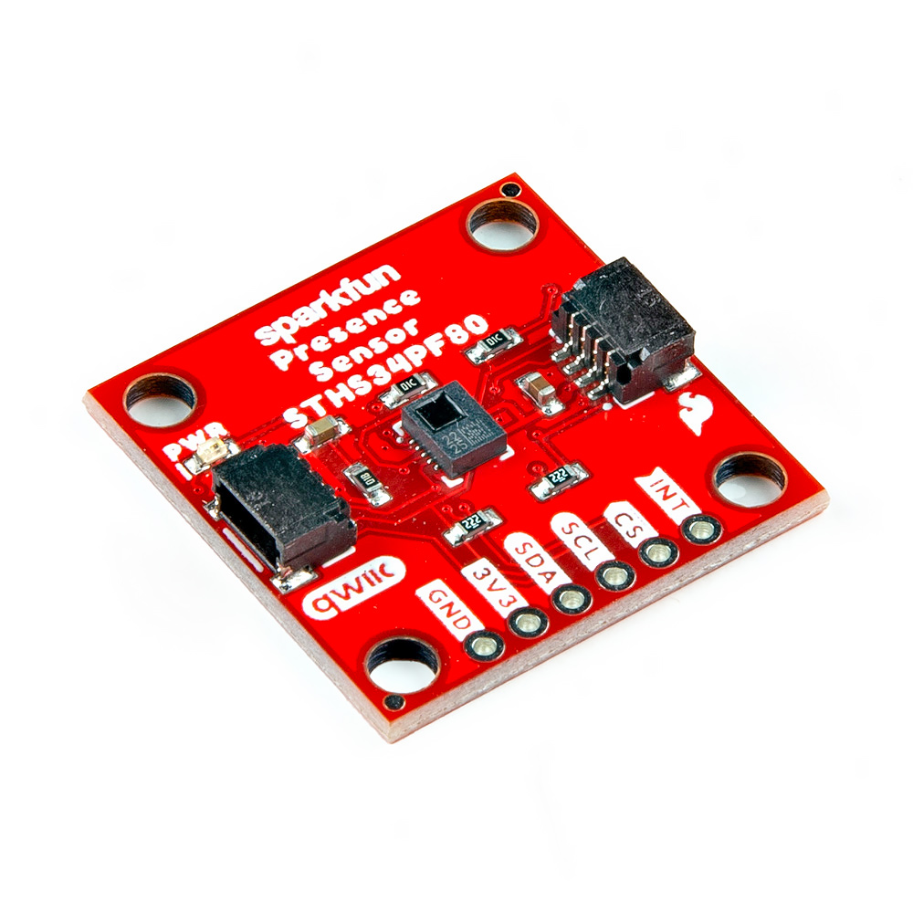
SparkFun Human Presence and Motion Sensor - STHS34PF80 (Qwiic)
SEN-22494 -
SparkFun Qwiic Mini Human Presence and Motion Sensor - STHS34PF80
SEN-23253
Headers and Wiring
To add headers or hookup wires, users will need soldering equipment and headers/wire.
New to soldering?
Check out our How to Solder: Through-Hole Soldering tutorial for a quick introduction!
-

How to Solder: Through-Hole Soldering
-
Solder Lead Free - 100-gram Spool
TOL-09325 -
Weller WLC100 Soldering Station
TOL-14228 -
Chip Quik No-Clean Flux Pen - 10mL
TOL-14579 -
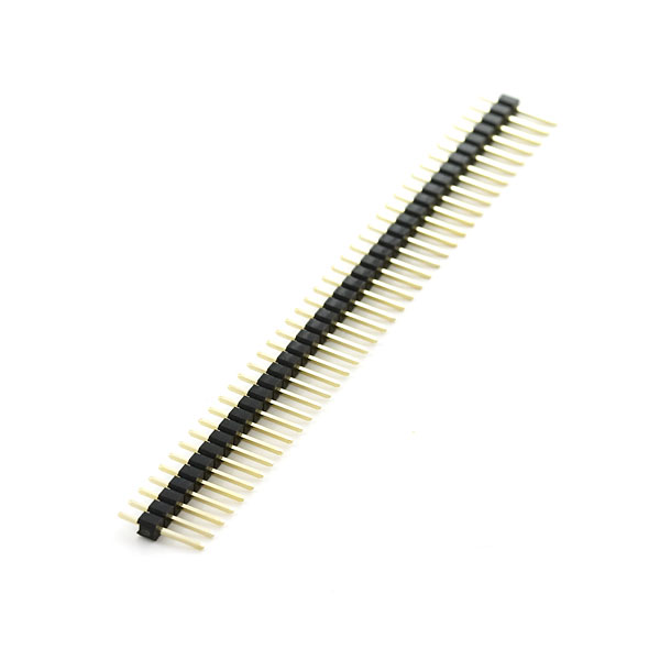
Break Away Headers - Straight
PRT-00116 -
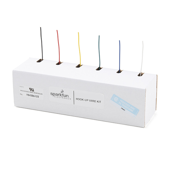
Hook-Up Wire - Assortment (Stranded, 22 AWG)
PRT-11375
Jumper Modification
To modify the jumpers, users will need soldering equipment and/or a hobby knife.
New to jumper pads?
Check out our Jumper Pads and PCB Traces Tutorial for a quick introduction!
-

How to Work with Jumper Pads and PCB Traces
-
Solder Lead Free - 100-gram Spool
TOL-09325 -
Weller WLC100 Soldering Station
TOL-14228 -
Chip Quik No-Clean Flux Pen - 10mL
TOL-14579 -
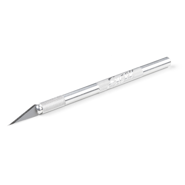
Hobby Knife
TOL-09200
Suggested Reading
As a more sophisticated product, we will skip over the more fundamental tutorials (i.e. Ohm's Law and What is Electricity?). However, below are a few tutorials that may help users familiarize themselves with various aspects of the board.
-

Installing the Arduino IDE
-
Installing an Arduino Library
-

How to Install CH340 Drivers
-
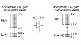
Logic Levels
-
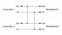
I2C
-
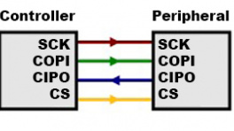
SPI
-
Serial Terminal Basics
-
How to Solder: Through-Hole Soldering
-
How to Work with Jumper Pads and PCB Traces
Hardware Overview
Board Dimensions
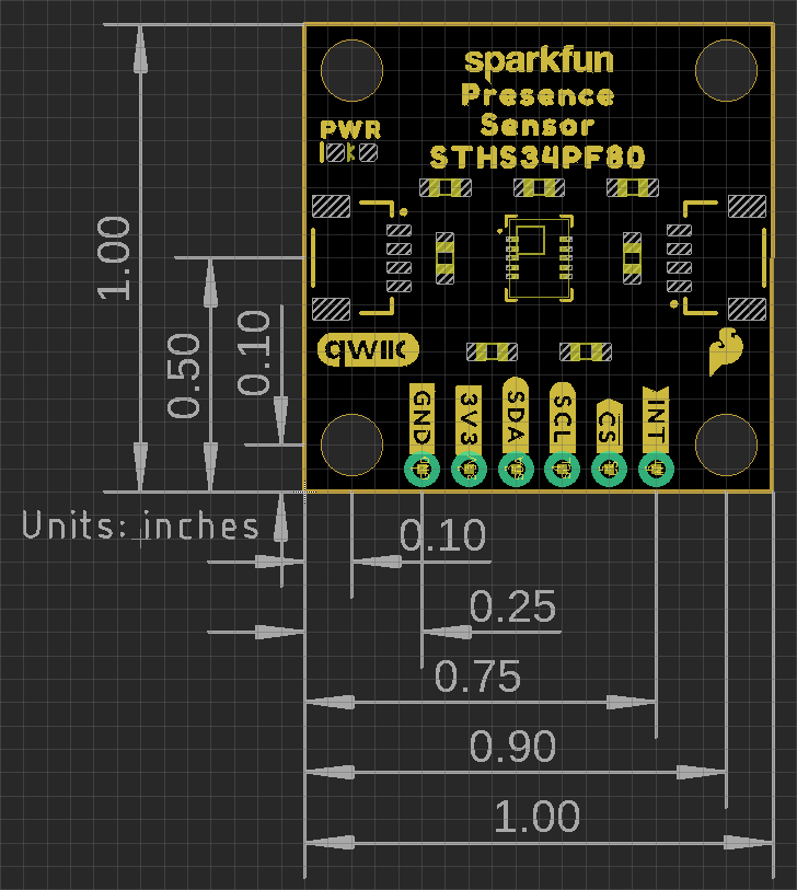
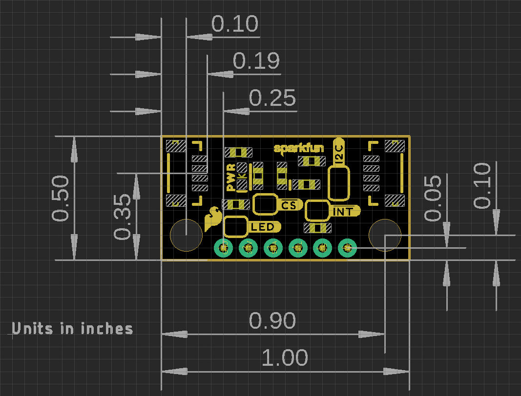
The Qwiic Mini Human Presence and Motion Sensor breakout boards are laid out in the standardized 0.5"x 1" (1.77 x 2.54 cm) mini form-factor and the normal, 1" x 1" (2.54 x 2.54 cm) Qwiic breakout board. These boards also include standard 0.13" mounting holes, which are compatible with 4-40 screws. The dimensions of these boards are illustrated in the drawings below, where the listed measurements are in inches.
Need more measurements?
For more information about the board's dimensions, users can download the eagle files for the board. These files can be opened in Eagle and additional measurements can be made with the dimensions tool.
Eagle - Free Download!
Eagle is a CAD program for electronics that is free to use for hobbyists and students. However, it does require an account registration to utilize the software.
 Dimensions Tool
This video from Autodesk demonstrates how to utilize the dimensions tool in Eagle, to include additional measurements:

Power
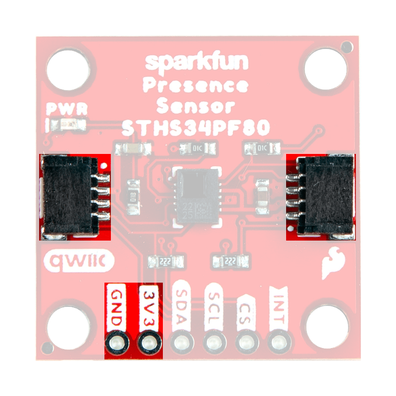
The STHS34PF80 requires a supply voltage between 1.7V to 3.6V. This power can be provided to the board, either, through one of the polarized Qwiic connectors or the dedicated 3.3V and GND PTH pins broken out on the board.

Info
The Qwiic connect system is meant to run on 3.3V. Ensure that another voltage is not being supplied, when utilized in conjunction with this system.
Info
For more details, users can reference the schematic and the STHS34PF80 datasheet.
Power Status LED
The red, PWR LED will light up once 1.4V is supplied to the board; however, for most users, it will light up when 3.3V is supplied through the Qwiic connector. A jumper is available to disconnect the power from the LED, for low-power applications (see Jumpers section below).


Minimum Voltage
Users should keep in mind that the forward voltage of the red LED is lower than the minimum voltage required to power the STHS34PF80 sensor. Therefore, the LED could potentially be lit, when there isn't enough voltage to power the sensor.
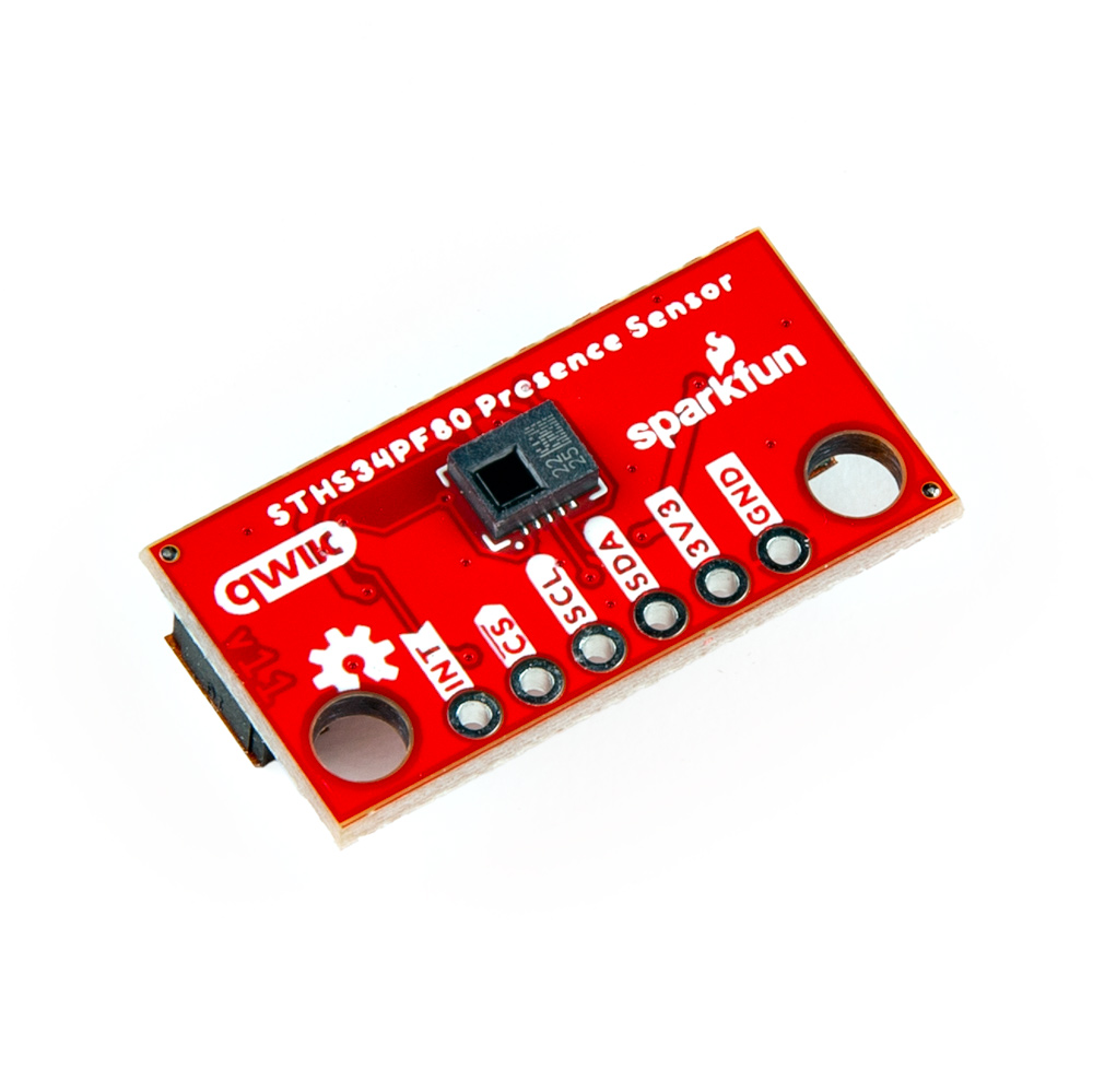
STHS34PF80
The Qwiic Human Presence/Motion Sensor board features the STHS34PF80 sensor from ST Microelectronics. Composed of a matrix of floating vacuum thermal transistors MOS, the sensor measures the ambient temperature and detects the black-body radiation of objects within its 80° field of view. The sensor's transistor array is split into two parts, one exposed to IR radiation and the other one shielded. The differential reading between the segments, allows the sensor to remove self-heating effects.
The sensor can operate in multiple lighting conditions and is unaffected by visible light or other bands thanks to the 5 to 20µm optical band-pass filter. The STHS34PF80 also incorporates algorithms to detect and discriminate between stationary and moving objects. These features enable the sensor to work as a human presence and motion sensor in different applications such as alarm systems, anti-intruder systems, smart lighting, and room occupancy. With an output data rates between 0.25 to 30 Hz and an available single-shot measurement from the STHS34PF80, all of which can be accessed through its I2C/SPI interface.
Features:
- I2C Address (7-bit): 0x5A (
1011010) - Operating Voltage: 1.7 to 3.6V
- Current Draw: 10µA
- Range: 4m (objects 70 x 25 cm² in size)
- Field of View: 80°
- Optical wavelength: 5 to 20µm
- Built-in Detection Algorithms:
- Identify stationary objects
- Distinguish between stationary and moving objects
- Output Data Rate: 0.25 to 30Hz
- IR sensitivity: 2000 LSB/°C
- RMS noise: 25 LSBrms
- Operating Temperature: -40 to 85°C (1)
- Sensor accuracy: ±0.6°C (local) (2)
- Factory calibrated
- The operational temperature range of the sensor is
- The accuracy specifications only apply under settled isothermal conditions.
Current Consumption
The average current consumption by the STHS34PF80 is 10µA with 1.5µA in power-down mode.

The STHS34PF80 sensor on the Qwiic Human Presence/Motion Sensor boards.
Operation Modes
The STHS34PF80 has three operation modes:
- Power-down: After the boot is completed, the device is automatically configured in power-down mode.
- One-shot: When configured in one-shot mode, the device can read environmental data at the very moment the controlling MCU requires it.
- Continuous: When configured in continuous mode, the device keeps reading data at predefined frequencies (fixed output data rates, ODRs).
In both one-shot mode and continuous mode, the STHS34PF80 allows performing prior averaging (filtering) of the values of ambient temperature and object temperature to obtain smoother outputs.
Info
For more details, users can refer to Section 3 of the AN5867 - Operation Manual.
Smart Detection Algorithms
The STHS34PF80 has three detection modes that are provided by the built-in smart algorithms:
- Presence detection
- Motion detection
- Ambient temperature shock detection
*These are not available when wide mode is configured.
Info
For more details, users can refer to Section 7 of the AN5867 - Operation Manual.
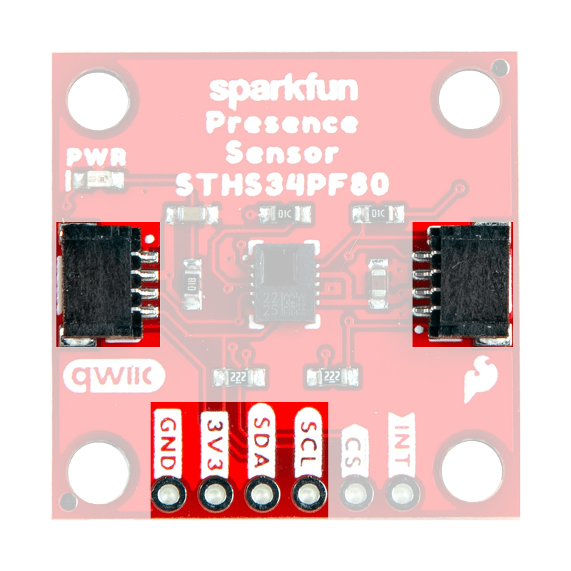
Breakout Pins
There are six PTH pins broken out on the Qwiic Human Presence/Motion Sensor boards. The pins are evenly spaced at 0.1" on the outer edge of the board; perfect for attaching headers. These pins provide access to the I2C and SPI interfaces of the STHS34PF80 sensor, including the interrupt pin.
Note
The I2C interface can also be accessed through the Qwiic connectors on the board.
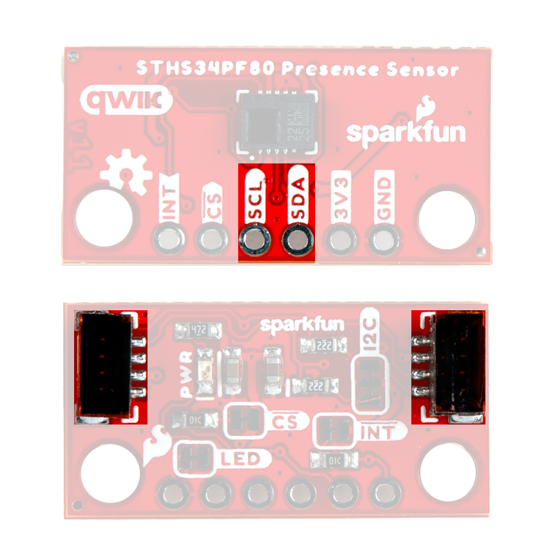
I2C Pins
The I2C interface can also be accessed either through the breakout pins or the Qwiic connectors on the board. In most cases, the Qwiic connector will be the simplest method to connect the Qwiic Human Presence/Motion Sensor boards to a microcontroller. The I2C interface is enabled by default on the Qwiic Human Presence/Motion Sensor boards.

Enabling the I2C Interface
The I2C interface is enabled by default on the Qwiic Human Presence/Motion Sensor boards. To disable the I2C interface and enable the SPI interface, users must ensure that the CS pin is initially pulled down (0).
Qwiic Connector
Qwiic connectors are provided for users to seamlessly integrate I2C devices with SparkFun's Qwiic Ecosystem.

SPI Pins
The STHS34PF80 sensor operates in a 3-wire SPI configuration. In a 3-wire mode, the data signal lines are combined into a single bidirectional data line. The data transactions are half-duplex to allow for bidirectional communication.
| Label | Pin | Function |
|---|---|---|
SCL |
SPC |
Clock signal |
SDA |
SDIO |
Serial data (In/Out) |
CS |
CS |
Chip select:1: I²C enabled0: SPI enabled
|
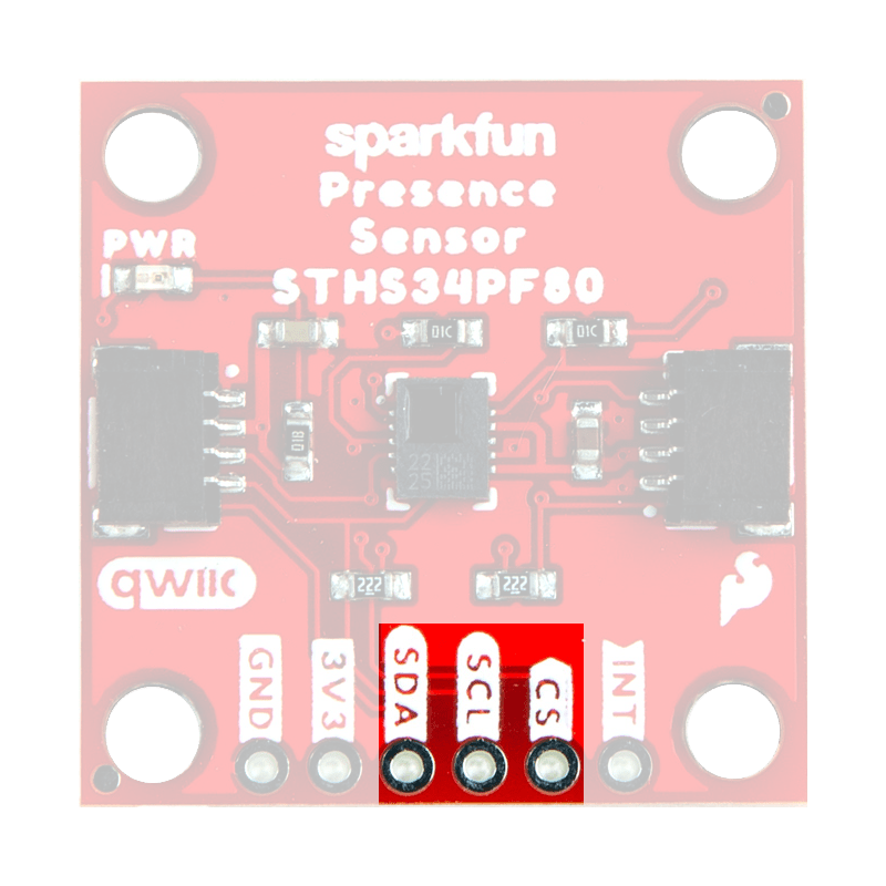

Enabling the SPI Interface
The I2C interface is enabled by default on the Qwiic Human Presence/Motion Sensor boards. To disable the I2C interface and enable the SPI interface, users must ensure that the CS pin is initially pulled down. (On boot-up, the CS must be in a LOW state to enable the SPI interface.)
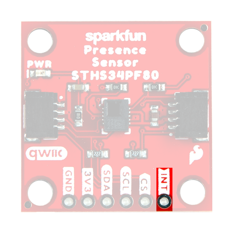
Interrupt Pin
By default, the interrupt pin signals when data is available. However, the detection mode employed by the sensor can also trigger an interrupt.

Qwiic Connectors
Qwiic connectors are provided for users to seamlessly integrate with SparkFun's Qwiic Ecosystem. Otherwise, users can access the I2C interface through the PTH pins broken out on the board.

What is Qwiic?
The Qwiic connect system is a solderless, polarized connection system that allows users to seamlessly daisy chain I2C boards together. Play the video, to learn more about the Qwiic connect system or click on the banner above to learn more about Qwiic products.

Features of the Qwiic System


Qwiic cables (4-pin JST) plug easily from development boards to sensors, shields, accessory boards and more, making easy work of setting up a new prototype.


There's no need to worry about accidentally swapping the SDA and SCL wires on your breadboard. The Qwiic connector is polarized so you know you’ll have it wired correctly every time.
The part numbers for the PCB connector is SM04B-SRSS (Datasheet) and the mating connector on the cables is SHR04V-S-B; or an equivalent 1mm pitch, 4-pin JST connection.


It’s time to leverage the power of the I2C bus! Most Qwiic boards will have two or more connectors on them, allowing multiple devices to be connected.
Jumpers
Never modified a jumper before?
Check out our Jumper Pads and PCB Traces tutorial for a quick introduction!
-
How to Work with Jumper Pads and PCB Traces
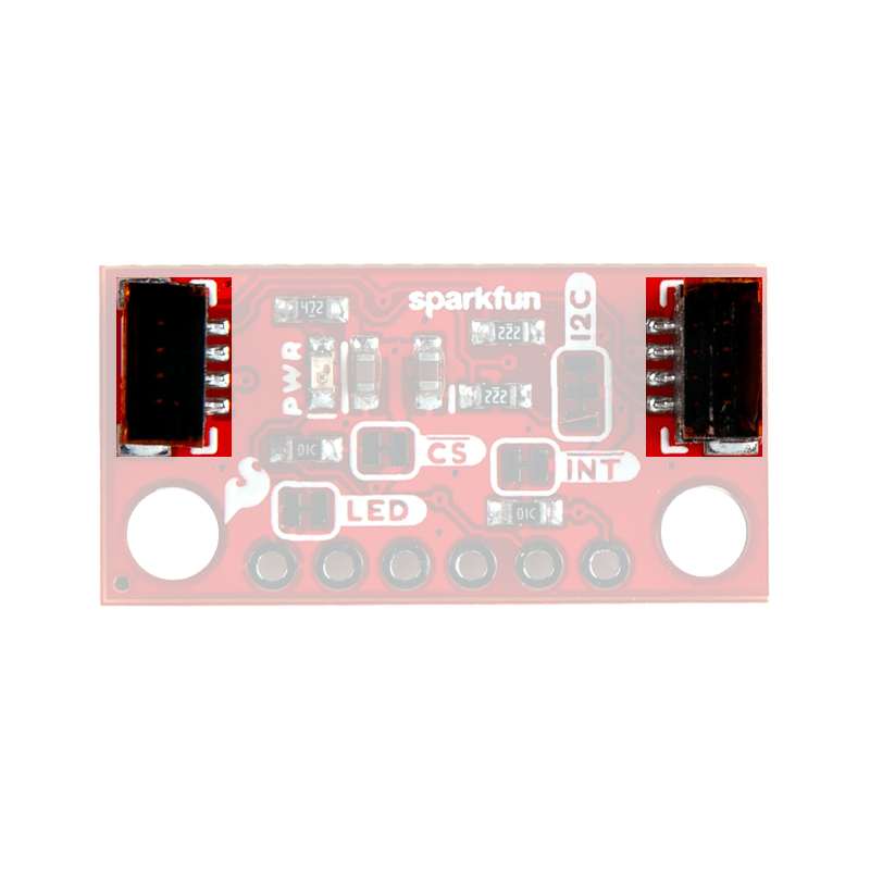
There are four jumpers on the back of the board that can be used to easily modify the hardware connections of the board.
- LED - This jumper can be used to disconnect power from the red, power LED for low-power applications.
- I2C - This jumper can be used to remove the pull-up resistors on the I2C bus.
- INT - This jumper can be used to remove the pull-up resistor from the
INTpin. - CS - This jumper can be used to remove the pull-up resistor from the
CSpin.- The state of the
CSpin on boot-up, controls whether the I2C or SPI interface is enabled. (1)
- The state of the
-
Info
1: I²C enabled0: SPI enabled
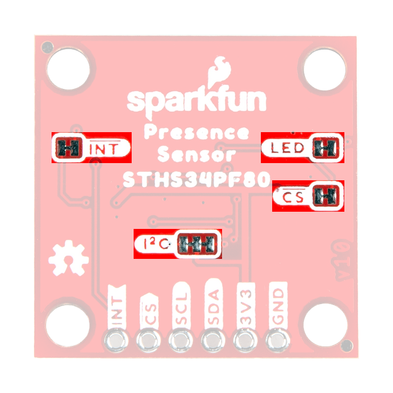
Jumpers on the back of the Qwiic Human Presence/Motion Sensor board.

Jumpers on the Qwiic Mini Human Presence/Motion Sensor board.
Hardware Assembly
Qwiic Cable
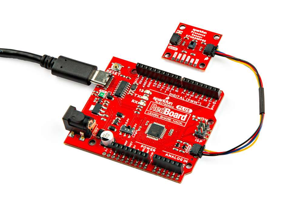
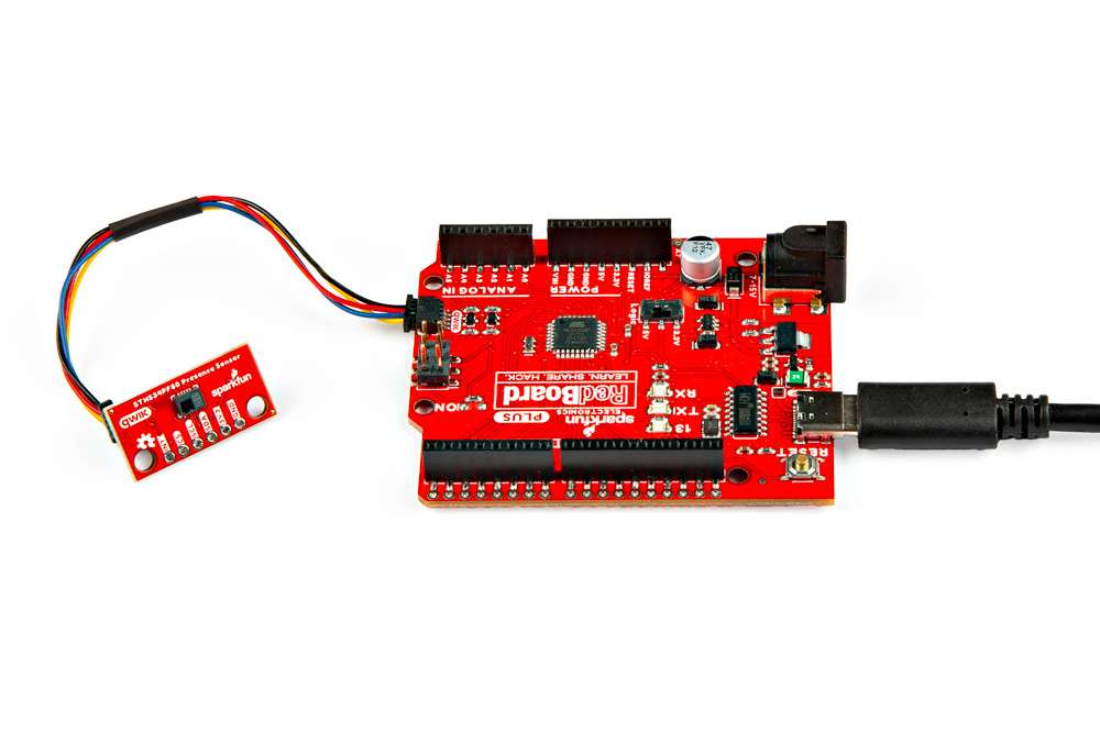
The simplest method to connect a microcontroller to a Qwiic Human Presence/Motion Sensor board is through the Qwiic connector.
Connecting a Qwiic cable to the Qwiic Human Presence/Motion Sensor board.
Info
The Qwiic connection system is a standardized solderless, polarized connector interface that allows users to seamlessly daisy chain I2C boards together.
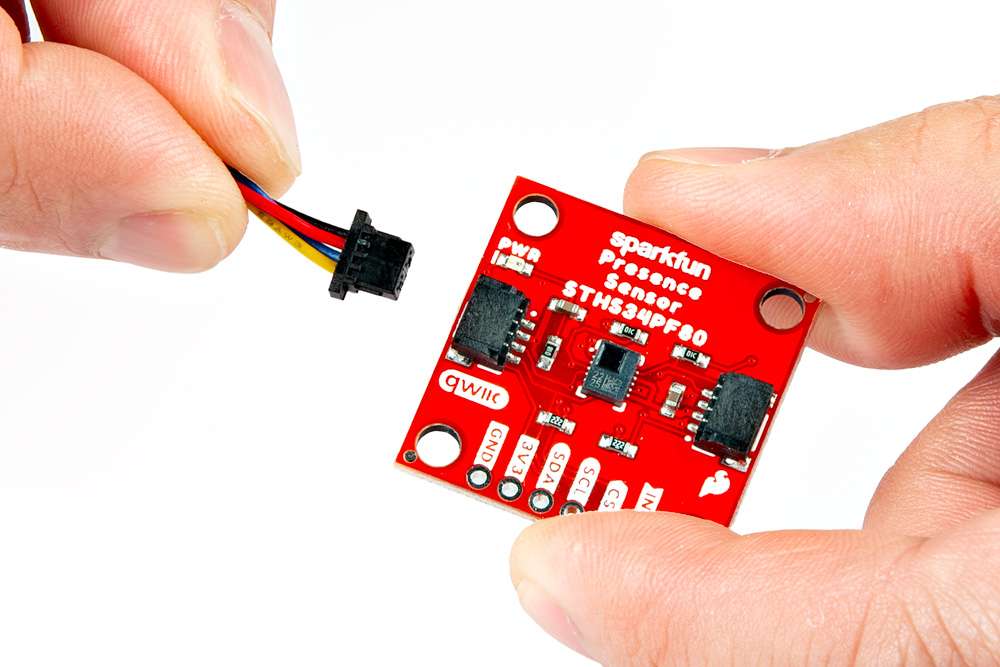
Remove Tape
Users with the mini version of the Qwiic Human Presence/Motion Sensor board should remove the tape covering the Qwiic connector.

Note
The tweezers are not necessary, they were only used for illustration purposes. (Fingers would have obscured the camera shot.)
Info
The tape is used by the pick-and-place machine to place the connector on the board during assembly.
Breakout Pins
The PTH pins on the Qwiic Human Presence/Motion Sensor board are broken out into 0.1"-spaced pins on the outer edge of the board.
New to soldering?
If you have never soldered before or need a quick refresher, check out our How to Solder: Through-Hole Soldering guide.
-
How to Solder: Through-Hole Soldering
Hookup Wires
For a more permanent connection, users can solder wires directly to the board.

Soldering wires to the Qwiic Mini Human Presence/Motion Sensor board.
Headers
When selecting headers, be sure you are aware of the functionality or physical arrangement required.

Soldering headers to the Qwiic Human Presence/Motion Sensor board.
Software Overview
Arduino IDE
Tip
For first-time users, who have never programmed before and are looking to use the Arduino IDE, we recommend beginning with the SparkFun Inventor's Kit (SIK), which is designed to help users get started programming with the Arduino IDE.
Most users may already be familiar with the Arduino IDE and its use. However, for those of you who have never heard the name Arduino before, feel free to check out the Arduino website. To get started with using the Arduino IDE, check out our tutorials below:
-
What is an Arduino?
-
Installing the Arduino IDE
-
Installing an Arduino Library
-
Installing Board Definitions in the Arduino IDE
Need help setting up the RedBoard Plus?
RedBoard Plus
The following instructions should help users get started with the RedBoard Plus. For more information about the board, please check out our hookup guide below:
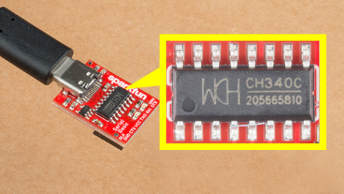
CH340 Driver
Users will need to install the appropriate driver for their computer to recognize the serial-to-UART chip on their board/adapter. Most of the latest operating systems will recognize the CH340C chip on the board and automatically install the required driver.
To manually install the CH340 driver on their computer, users can download it from the WCH website. For more information, check out our How to Install CH340 Drivers Tutorial.
Selecting a Board
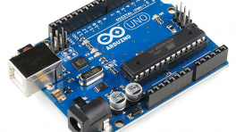
When selecting a board to program in the Arduino IDE, users should select the Arduino Uno from the Tools drop-down menu (_i.e. Tools > Board > Arduino AVR Boards > Arduino Uno).

Arduino IDE 2.x.x - Alternative Method
In the newest version of the Arduino IDE 2.x.x, users can also select their board (green) and port (blue) from the Select Board & Port dropdown menu (yellow).

SparkFun STHS34PF80 Arduino Library
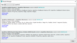
The SparkFun STHS34PF80 Arduino library can be installed from the library manager in the Arduino IDE by searching for:
SparkFun STHS34PF80 Arduino library

SparkFun STHS34PF80 Arduino library in the library manager of the Arduino IDE.
Manually Downloading the Arduino Library
For users who would like to manually download and install the library, the *.zip file can be accessed from the GitHub repository or downloaded by clicking the button below.
Example - Basic
Once the Arduino library has been installed, the Example1_BasicReadings.ino example file can be accessed from the File > Examples > SparkFun STHS34PF80 Arduino Library > Example1_BasicReadings drop-down menu. This example reads the human presence detection values from the STHS34PF80 sensor through the I2C interface and displays them in the Serial Monitor.
Example1_BasicReadings.ino
Code Verification
This code was last verified to be functional under the following parameters:
IDE: Arduino 2.2.1
Hardware Platform: SparkFun RedBoard Qwiic
SparkFun Human Presence and Motion Sensor - STHS34PF80 (Qwiic) Version: 1.0
SparkFun Qwiic Mini Human Presence and Motion Sensor - STHS34PF80 Version: 1.0
1 2 3 4 5 6 7 8 9 10 11 12 13 14 15 16 17 18 19 20 21 22 23 24 25 26 27 28 29 30 31 32 33 34 35 36 37 38 39 40 41 42 43 44 45 46 47 48 49 50 51 52 53 54 55 56 57 58 59 60 61 62 63 64 65 66 67 68 69 70 71 72 73 74 75 76 77 78 79 80 81 82 83 84 85 86 87 88 89 90 91 92 93 94 95 96 97 98 99 100 101 102 103 104 105 106 107 108 109 110 111 | |
Hardware Connections
For this example, users simply need to connect their Qwiic Human Presence/Motion Sensor board to their microcontroller, utilizing the I2C interface. With the recommended hardware, users can easily connect their boards with the Qwiic connection system.
Pin Connections
For users with a development board without a Qwiic connector, the table below illustrates the required pin connections. Make sure that the logic-level of the sensor is compatible with the development board that is being connected.
| Sensor Pin | Microcontroller Pin | RedBoard/Uno |
|---|---|---|
SCL |
I2C - Serial Clock | SCL/A5 |
SDA |
I2C - Serial Data | SDA/A4 |
3V3 |
Power: 1.7 to 3.6V | 3.3V |
GND |
Ground | GND |
Serial Monitor
This example reads the human presence detection values from the STHS34PF80 sensor and displays them in the Serial Monitor. It prints the raw IR presence (cm-1), if the motion detection flag was triggered, and temperature (°C).
The human presence detection values being streamed from the STHS34PF80 sensor into the Serial Monitor.
Tip
For this example wave different objects in front of the sensor, with varying ranges. Objects that emit black body radiation work the best and should trigger the motion detected flag.
Example - Interrupt
The Example2_Interrupts.ino example file can be accessed from the File > Examples > SparkFun STHS34PF80 Arduino Library > Example2_Interrupts drop-down menu. This example builds upon the previous code in Example1_BasicReadings.ino. Instead of constantly streaming the human presence detection values from the STHS34PF80 sensor, the microcontroller waits until an interrupt is triggered before data is retrieved through the I2C interface.
Example2_Interrupts.ino
Code Verification
This code was last verified to be functional under the following parameters:
IDE: Arduino 2.2.1
Hardware Platform: SparkFun RedBoard Qwiic
SparkFun Human Presence and Motion Sensor - STHS34PF80 (Qwiic) Version: 1.0
SparkFun Qwiic Mini Human Presence and Motion Sensor - STHS34PF80 Version: 1.0
1 2 3 4 5 6 7 8 9 10 11 12 13 14 15 16 17 18 19 20 21 22 23 24 25 26 27 28 29 30 31 32 33 34 35 36 37 38 39 40 41 42 43 44 45 46 47 48 49 50 51 52 53 54 55 56 57 58 59 60 61 62 63 64 65 66 67 68 69 70 71 72 73 74 75 76 77 78 79 80 81 82 83 84 85 86 87 88 89 90 91 92 93 94 95 96 97 98 99 100 101 102 103 104 105 106 107 108 109 110 111 112 113 114 115 116 117 118 119 120 121 122 123 124 | |
Hardware Connections
For this example, users simply need to connect their Qwiic Human Presence/Motion Sensor board to their microcontroller, utilizing the I2C interface and interrupt pin. Users can easily connect the I2C interface with the Qwiic connection system on their boards. To connect the interrupt pin, we recommend utilizing an IC-hook for a temporary connection.

Pin Connections
For users with a development board without a Qwiic connector, the table below illustrates the required pin connections. Make sure that the logic-level of the sensor is compatible with the development board that is being connected.
| Sensor Pin | Microcontroller Pin | RedBoard/Uno |
|---|---|---|
INT |
Interrupt Pin | D2 |
SCL |
I2C - Serial Clock | SCL/A5 |
SDA |
I2C - Serial Data | SDA/A4 |
3V3 |
Power: 1.7 to 3.6V | 3.3V |
GND |
Ground | GND |
Serial Monitor
This example waits until an interrupt is triggered by one of the detection modes before the raw IR presence value (cm-1) is retrieved from the STHS34PF80 sensor. The data is then displayed in the Serial Monitor.

The human presence detection values being streamed from the STHS34PF80 sensor into the Serial Monitor.
Tip
For this example wave different objects in front of the sensor, with varying ranges in and out of the sensor's field of view. Objects that emit black body radiation work the best and should trigger the interrupt.
Example - SPI
This example doesn't currently operate properly; we are actively looking into the issue. To track our progress, please refer to this [GitHub issue](https://github.com/sparkfun/SparkFun_STHS34PF80_Arduino_Library/issues/7).
Description
The Example4_SPIFunctionality.ino example file can be accessed from the File > Examples > SparkFun STHS34PF80 Arduino Library > Example4_SPIFunctionality drop-down menu. This example operates similarly to the code in Example1_BasicReadings.ino. Instead of retrieving data through the I2C interface, the serial peripheral interface (SPI) is used to access the human presence detection values from the STHS34PF80 sensor.
Example4_SPIFunctionality.ino
Code Verification
This code was last verified to be functional under the following parameters:
IDE: Arduino 2.2.1
Hardware Platform: SparkFun RedBoard Qwiic
SparkFun Human Presence and Motion Sensor - STHS34PF80 (Qwiic) Version: 1.0
SparkFun Qwiic Mini Human Presence and Motion Sensor - STHS34PF80 Version: 1.0
1 2 3 4 5 6 7 8 9 10 11 12 13 14 15 16 17 18 19 20 21 22 23 24 25 26 27 28 29 30 31 32 33 34 35 36 37 38 39 40 41 42 43 44 45 46 47 48 49 50 51 52 53 54 55 56 57 58 59 60 61 62 63 64 65 66 67 68 69 70 71 72 73 74 75 76 77 78 79 80 81 82 83 84 85 86 87 88 89 90 91 92 93 94 95 96 97 98 99 100 101 102 103 104 105 106 107 108 109 110 111 112 113 114 115 116 117 | |
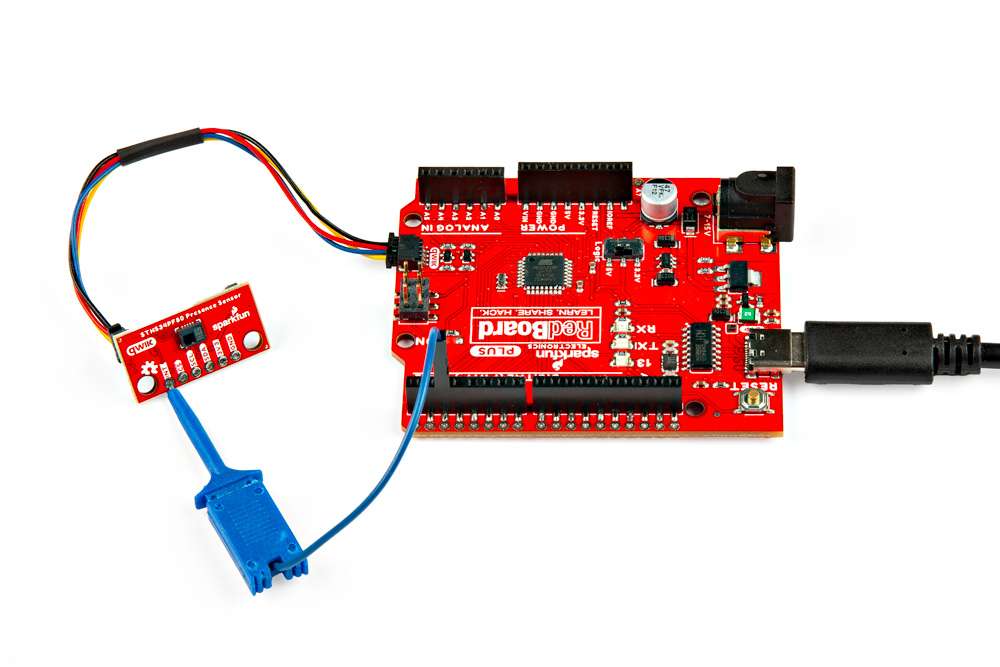
Hardware Connections
For this example, users will need to modify the CS jumper to enable the SPI communication. In the setups illustrated below, right-angle headers were soldered to the boards and connected with M/F jumper wires to the microcontroller. However, users should select a connection method that suits their needs.
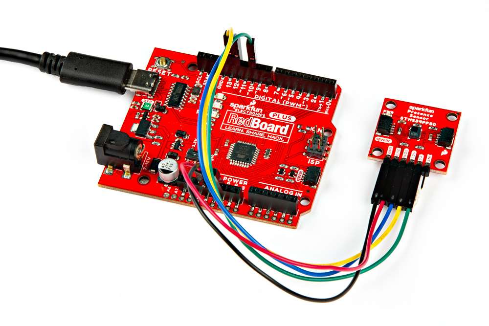
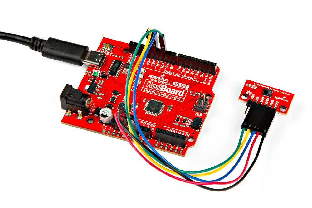
Pin Connections
Below are the pin connections for SPI communication with the sensor. Users should be aware of the logic-levels of their microcontroller; with the RedBoard Plus, users only need to flip a switch to configure all the board's pins to 3.3V-logic.
| Sensor Pin | Microcontroller Pin | RedBoard Plus |
|---|---|---|
CS |
SPI - Chip Select Pin | 10 |
SCL |
SPI - Serial Peripheral Clock | 13 |
SDA |
SPI - Serial Data In/Out | 12 |
3V3 |
Power: 1.7 to 3.6V | 3.3V |
GND |
Ground | GND |
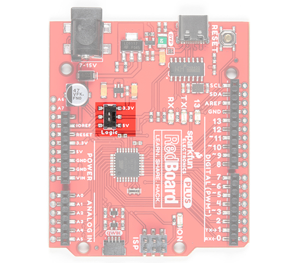
The logic-level switch on the RedBoard Plus.
Note
Users will need to initially pull the CS pin low, to enable the SPI communication on the Qwiic Human Presence/Motion Sensor boards.
Troubleshooting Tips
Need Help?
If you need technical assistance or more information on a product that is not working as you expected, we recommend heading on over to the SparkFun Technical Assistance page for some initial troubleshooting.
If you can't find what you need there, the SparkFun Forums is a great place to search product forums and ask questions.
Account Registration Required
If this is your first visit to our forum, you'll need to create a Forum Account to post questions.
Resources
Product Resources
-
Composite (Both Boards)
- Design Files:
- Arduino Library
- Component Documentation
- Hardware Repo
-
Human Presence and Motion Sensor - STHS34PF80 (Qwiic)
- Product Page
- Design Files:
-
Qwiic Mini Human Presence and Motion Sensor - STHS34PF80
- Product Page
- Design Files:
Additional Resources
🏭 Manufacturer's Resources
ST Microelectronics also provides additional resources for the STHS34PF805: