Qwiic OLED (0.91", 128x32)
Introduction
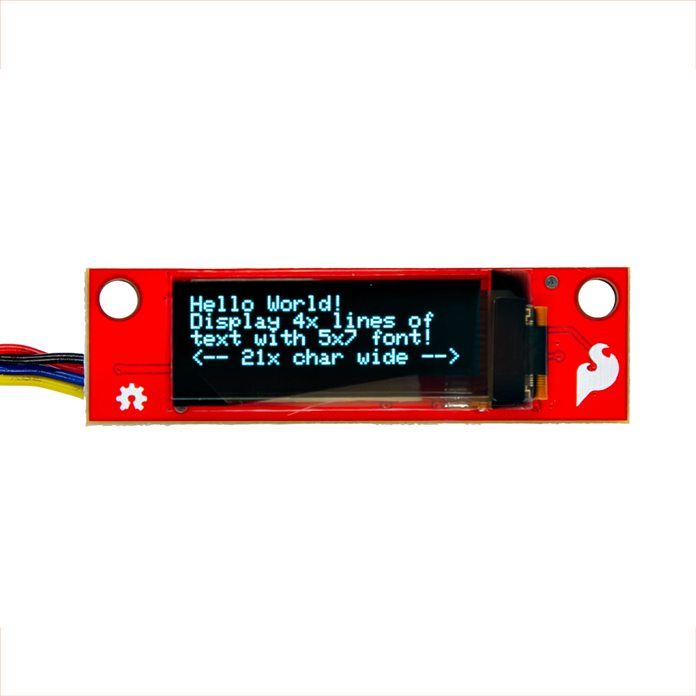
The SparkFun Qwiic OLED Display can display up to four lines of text and features 128x32 pixels in a small 0.91” (diagonal) frame. As an OLED, this display does not have a back light layer (unlike LCDs) and therefore it’s thinner, consumes less power, and has higher contrast.
In this section, we'll go over the hardware and how to hookup the breakout board.
Required Materials
To follow along with this tutorial, you will need the following materials. You may not need everything though depending on what you have. Add it to your cart, read through the guide, and adjust the cart as necessary.
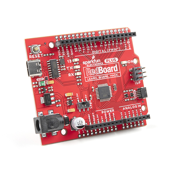
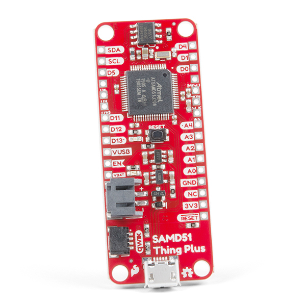
- 1x SparkFun RedBoard Plus [DEV-18158]
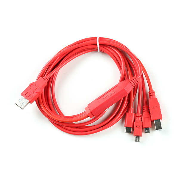
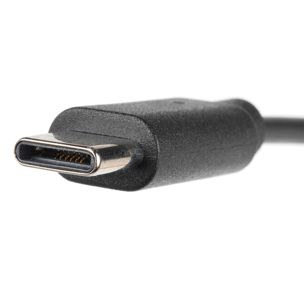
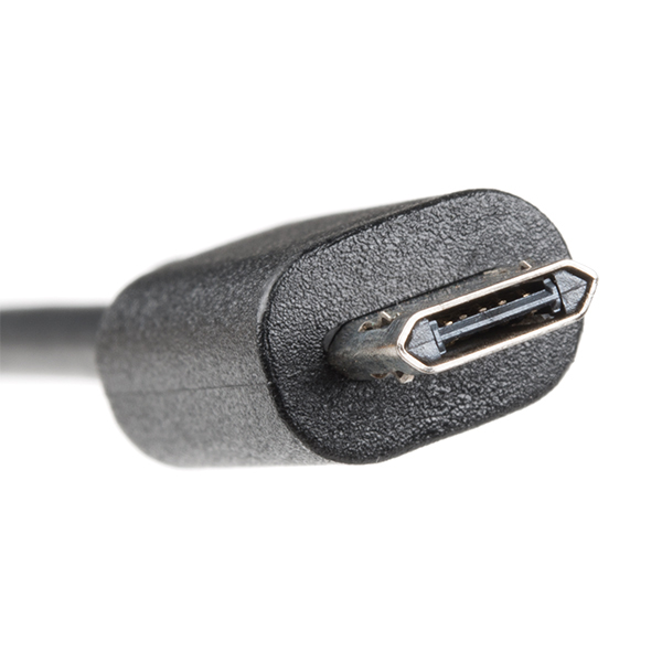
- 1x Reversible USB A to C Cable - 0.8m [CAB-15425]
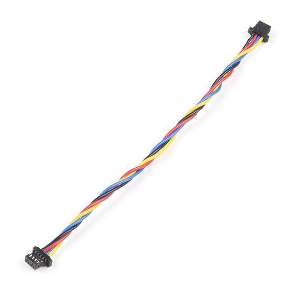
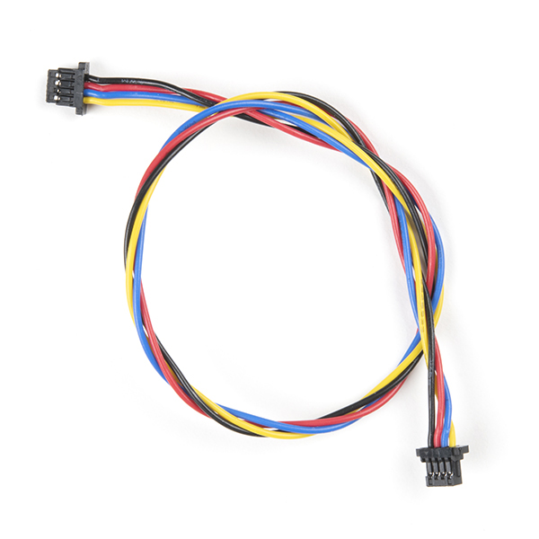
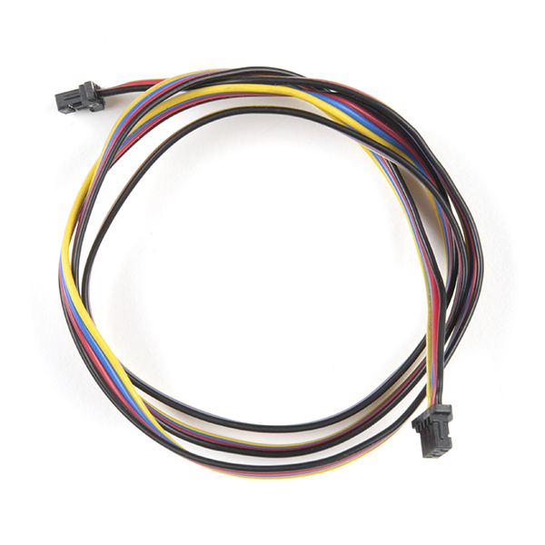
- 1x Qwiic Cable
- Flexible Qwiic Cable - 50mm [PRT-17260], for short distances
- Flexible Qwiic Cable - 500mm [PRT-17257], for those that need to wire the board farther away from your microcontroller
- 1x SparkFun Qwiic OLED Display (0.91 in., 128x32) [LCD-22495]
Microcontroller
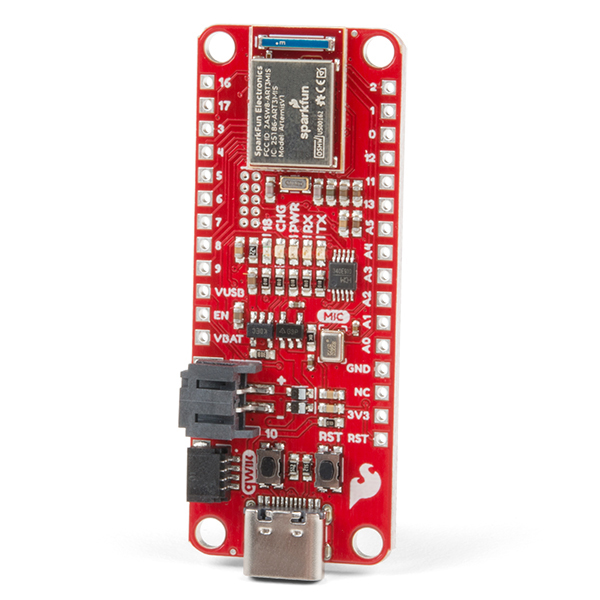
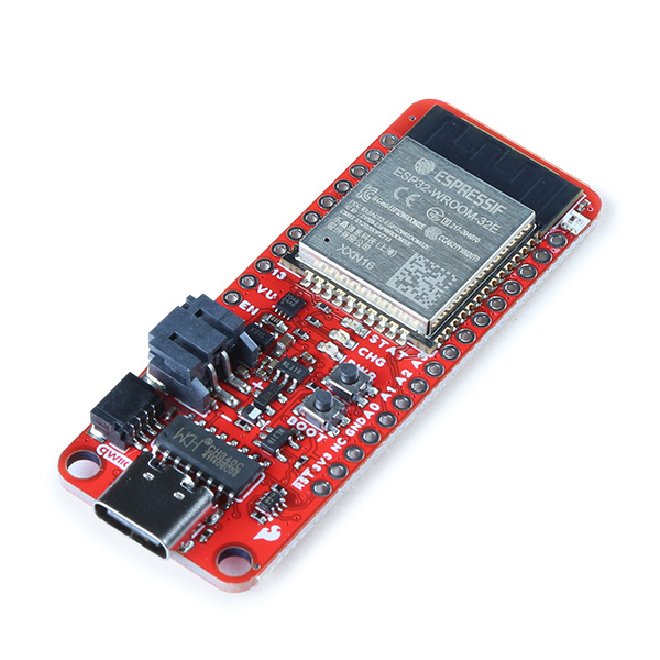
To get started, you'll need a microcontroller to, well, control everything. We used the RedBoard with the ATmega328P for the Qwiic micro OLED. However, any of the other microcontrollers that are compatible with the Qwiic OLED Arduino Library will work as well. Below are a few from the list that we provided earlier.
USB Cable
Below are a few USB cables from the SparkFun catalog. Make sure to grab the associated USB cable that is compatible with your microcontroller.
Qwiic
If the controller you choose doesn't have a built-in Qwiic connector, one of the following Qwiic shields that matches your preference of microcontroller is needed:
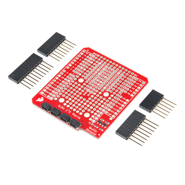
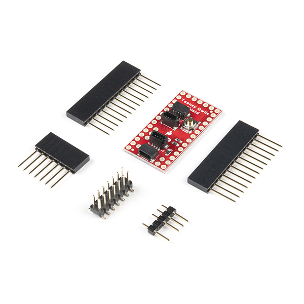
You will also need a Qwiic cable to connect the shield to your OLED, choose a length that suits your needs.

Of course, you will also need a Qwiic Micro OLED if you have not added that to you cart already.
Hardware Overview
In this section, we will highlight the hardware and pins that are broken out on the SparkFun Qwiic OLED Display (0.91 in., 128x32).
 |
 |
| Top View | Bottom View |
OLED Display (0.91", 128x32)
The OLED screen has a pixel resolution of 128x32, a panel size of 30.0mm x 11.5mm x 1.2mm, and an active area of 22.384mm x 5.584mm. The driver chip is the SSD1306. For information can be found in the datasheet linked in the Resources.
 |
| OLED Highlighted |
Note
The SparkFun Qwiic OLED Arduino Library works for multiple displays. However, there are some caveats in the size of the display with the text. While you can technically display all fonts in the narrow OLED display, some characters (numbers, letters, and/or symbols depending on the font) will be too big to fully display on the screen. For example, the fonts for the 31x48 (i.e. &QW_FONT_31X48) and large numbers (i.e. &QW_FONT_LARGENUM) are too big to fit within the display.
Using the OLED display (0.91", 128x32) we found that we were able to fit:
- 4x lines, 21x characters using the 5x7 (i.e.
&QW_FONT_5X7) - 2x lines, 14x characters using the 8x16 (i.e.
&QW_FONT_8X16) - 2x lines, 11x characters using the 7 segment (i.e.
&QW_FONT_7SEGMENT)
Power
Power is applied through the vertical Qwiic connectors on the back of the board. The recommended input voltage is 3.3V. The logic levels for the Qwiic OLED Display (0.9", 128x32) is 3.3V.
 |
| Power |
Qwiic and I2C
There are two vertical Qwiic connectors populated on the back of the board. You can use either connectors to provide power and send data through I2C. The Qwiic ecosystem is made for fast prototyping by removing the need for soldering. All you need to do is plug a Qwiic cable into the Qwiic connector and voila!
- SCL — I2C clock
- SDA — I2C data
- 3.3V — Power
- GND — Ground
|
| Vertical Qwiic Connectors |
The address of the display is 0x3C.
Note
On the back of the board, the power and I2C pins are broken out to test points. These are used in our production department for quality control using custom testbeds. These could be an alternative option to connect to the pins. However, we recommend using the Qwiic connectors to easily connect to the OLED display. Note that the I2C pins are also in a different order compared to a standard I2C Qwiic connector should you decide to solder to the test points.
 |
| I2C Test Points |
Jumpers
Note
If this is your first time working with jumpers, check out the How to Work with Jumper Pads and PCB Traces tutorial for more information.
The board includes a 1x3 jumper on the back of the board.
- I2C — This three way jumper labeled I2C is connected to two 4.7kΩ pull-up resistors to the I2C data and clock lines. For users that have multiple Qwiic-enabled devices with pull-up resistors enabled, the parallel equivalent resistance will create too strong of a pull-up for the bus to operate correctly. As a general rule of thumb, disable all but one pair of pull-up resistors if multiple devices are connected to the bus.
 |
| Jumpers Highlighted |
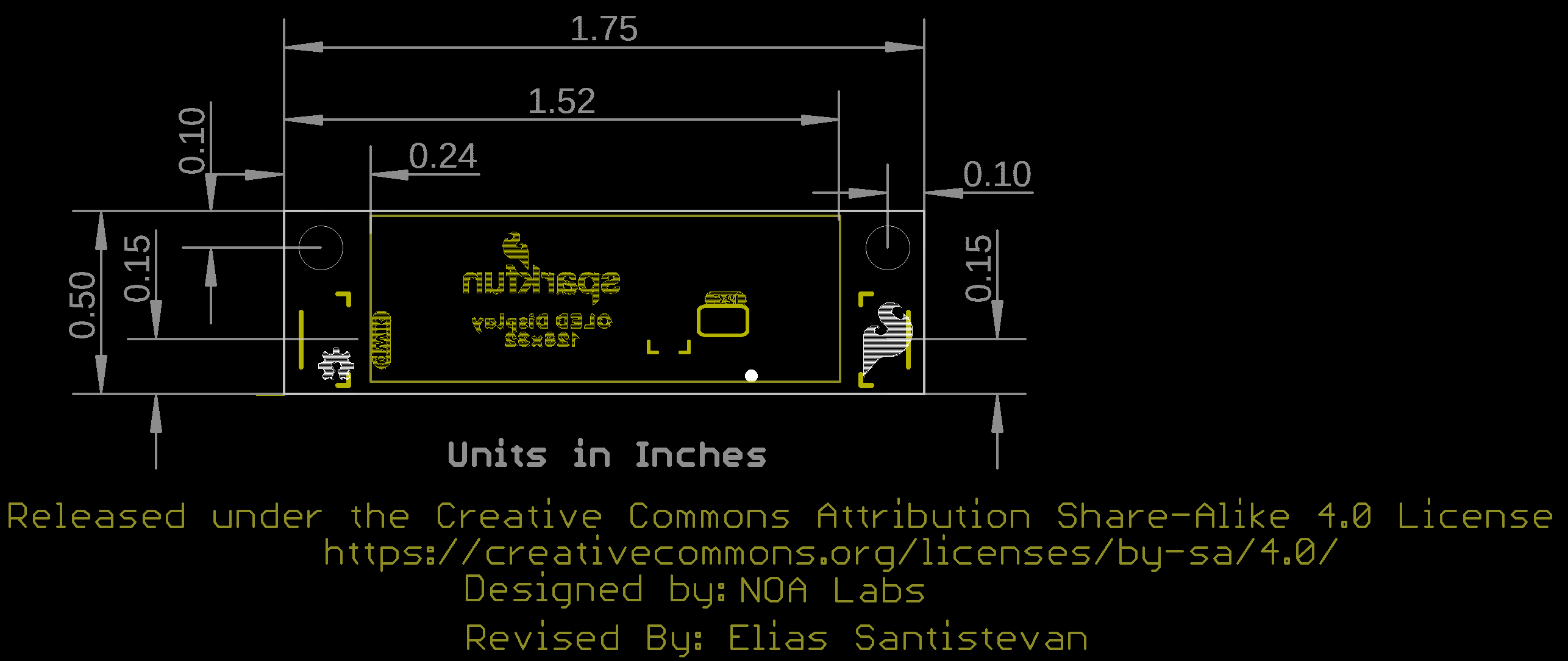
Board Dimensions
Version 1.1 is a bit smaller than previous versions since the board includes vertical Qwiic connectors on the back of the board. The overall board size is 1.75 in x 0.5 in. The mounting holes have also moved to toward the top of the board.
 |
| Board Dimensions |
Hardware Hookup
In this section, we'll go over how to connect to the display. We will go just a bit further and talk about how to mount the display.
Connecting via Qwiic Connector
Insert a Qwiic cable between your chosen microcontroller and Qwiic OLED. Then insert a USB cable between the microcontroller and your computer's COM port. For the scope of this tutorial, the USB cable provides power and allows us to upload code to the microcontroller. Of course, you can also debug the display by opening a Serial Terminal.
 |
| USB Cable, RedBoard Plus (ATMega328P), Qwiic Cable, Qwiic OLED (0.9 in., 12x32) |
Once you have finished prototyping, you could continue to use the USB cable and add a 5V power supply or battery pack.
Mounting the Qwiic OLED (0.9", 128x32)
Grab the board dimensions and cut out a rectangle in the enclosure. For users that want to mount the board so that the OLED display is flush against the enclosure, you will need to look at the dimensions based on the OLED. You will need to add a little tolerance so that the display can fit through the rectangle. For users that need to quickly mount the board, you will could also cut out rectangles based on the vertical Qwiic connector so that the wires can lead into the enclosure. Then cut out the mounting holes so that the board is right side up. In this case, we used a cardboard box as a quick example to demonstrate the Qwiic wires connecting leading into the enclosure.
 |
 |
| Qwiic OLED Display Mounted in an Enclosure | |
Note
To easily display text and graphics on the board, we recommend mounting the board right side up. There is an option in the example code to flip the text horizontally and vertically should you decide to mount the board upside down, but you would need to also determine the position of the text.
For a more durable enclosure, you could use wood, metal, or plastic. However, you will need additional tools to cut into the material.
Software
The Qwiic OLED (0.91", 128x32) uses the SparkFun QWIIC OLED Arduino Library. The SparkFun Qwiic OLED Library's Software Setup has instructions and usage examples. Additionally, the full library API documentation is available in the SparkFun Qwiic OLED Library API Reference guide.
Resources
Now that you've successfully got your OLED Display (0.9", 128x36) up and running, it's time to incorporate it into your own project! For more information, check out the resources below: