Qwiic Transparent Graphical OLED (1.51", 128x56)
Introduction
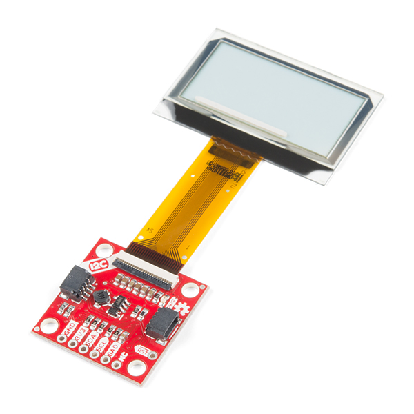
The future is here! You asked and we delivered - our Qwiic Transparent Graphical OLED Breakout allows you to display custom images on a transparent screen using either I2C or SPI connections.
With Qwiic connectors it's quick (ha ha) and easy to get started with your own images. However, we still have broken out 0.1"-spaced pins in case you prefer to use a breadboard. Brilliantly lit in the dark and still visible by daylight, this OLED sports a display area of 128x64 pixels, 128x56 of which are completely transparent. Control of the OLED is based on the HyperDisplay library or SparkFun Qwiic OLED Arduino Library! For the scope of this tutorial, we will be using the SparkFun Qwiic OLED Arduino Library.
This hookup guide will show you how to get started drawing objects and characters on your OLED.
Required Materials
To follow along with this tutorial, you will need the following materials. You may not need everything though depending on what you have. Add it to your cart, read through the guide, and adjust the cart as necessary.
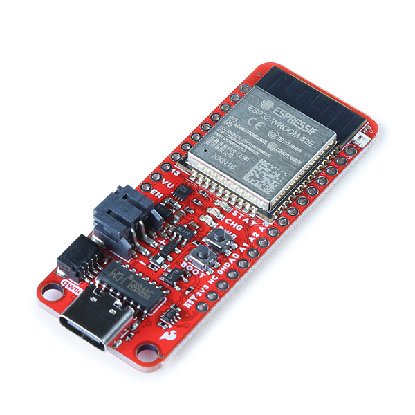
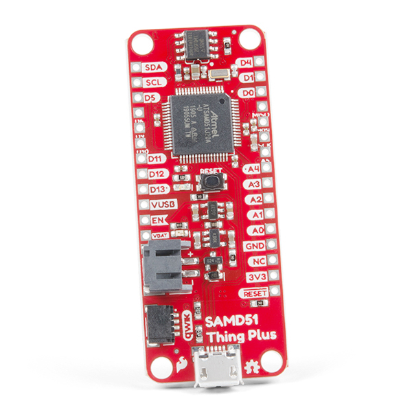
- 1x SparkFun Thing Plus - ESP32 WROOOM (USB-C) [WRL-20168]
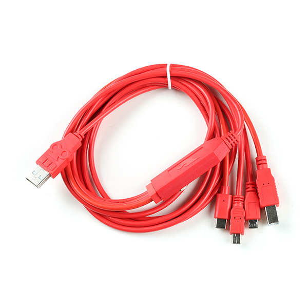
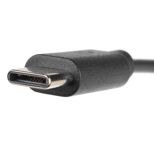
- 1x Reversible USB A to C Cable - 0.8m [CAB-15425]
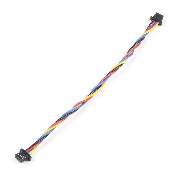
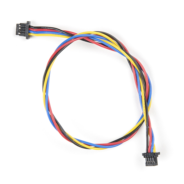
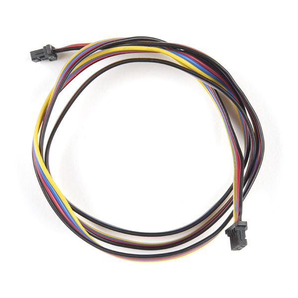
- 1x Qwiic Cable
- Flexible Qwiic Cable - 50mm [PRT-17260], for short distances
- Flexible Qwiic Cable - 500mm [PRT-17257], for those that need to wire the board farther away from your microcontroller
- 1x SparkFun Transparent Graphical OLED Breakout (Qwiic)[LCD-15173]
Microcontroller
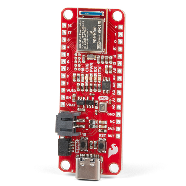
To get started, you'll need a microcontroller to, well, control everything. We used the SparkFun Thing Plus - ESP32 WROOOM. However, any of the other microcontrollers that are compatible with the Qwiic OLED Arduino Library will work as well. Below are a few from the list that we provided earlier.
USB Cable
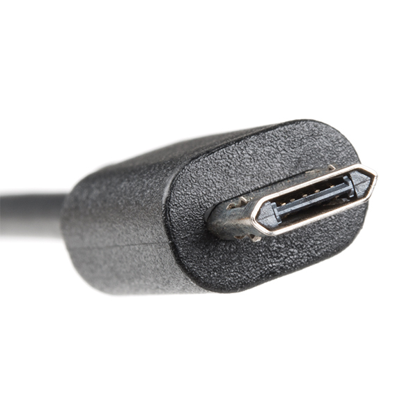
Below are a few USB cables from the SparkFun catalog. Make sure to grab the associated USB cable that is compatible with your microcontroller.
Qwiic
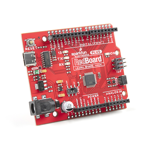
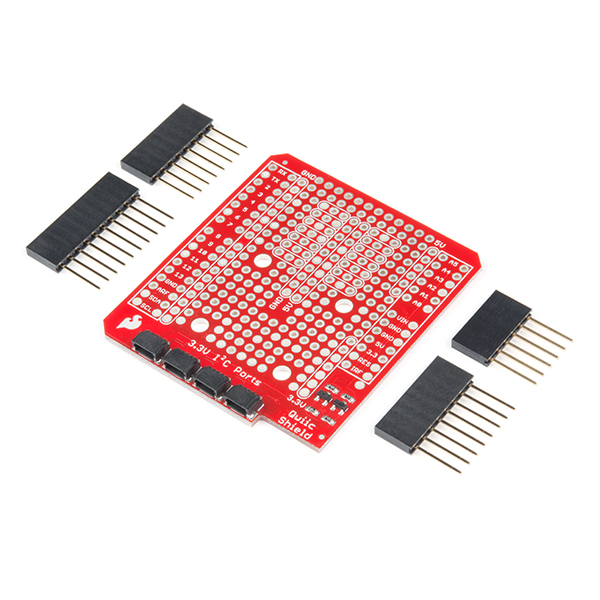
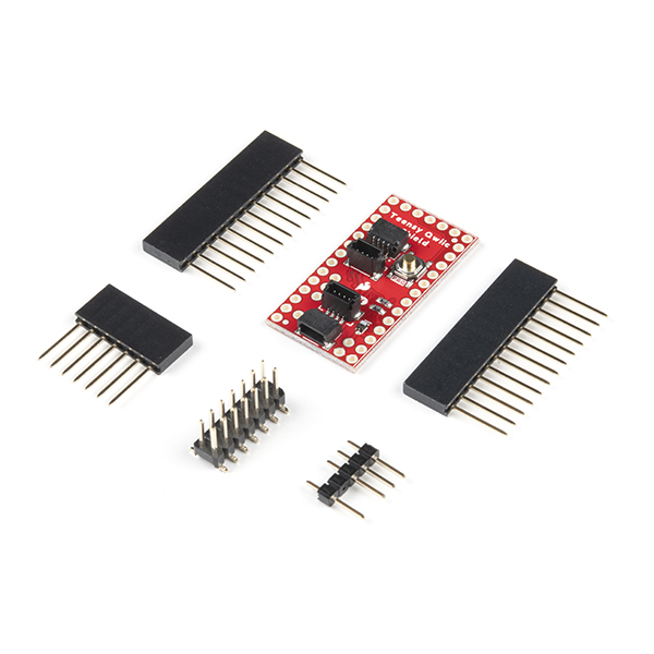
If the controller you choose doesn't have a built-in Qwiic connector, one of the following Qwiic shields that matches your preference of microcontroller is needed:
You will also need a Qwiic cable to connect the shield to your OLED, choose a length that suits your needs.

Of course, you will also need A Tranparent Graphical OLED Breakout if you have not added that to you cart already.

Suggested Reading
If you aren't familiar with the Qwiic Connection System, we recommend reading here for an overview.

We would also recommend taking a look at the following tutorials if you aren't familiar with them.
Hardware Overview
Listed below are some of the operating ranges and characteristics of the Transparent Graphical OLED Breakout.
| Characteristic | Range |
|---|---|
| Voltage | 1.65V-3.3V, typically 3.3V via the Qwiic Cable |
| Supply Current | 400 mA |
| I2C Address | 0X3C (Default), 0X3D (Closed Jumper) |
Graphical Display
The graphical display is where all the fun stuff happens. The glass itself measures 42mm x 27.16mm, with a pixel display that is 35.5 x 18mm. It houses 128x64 pixels, 128x56 of which are transparent.
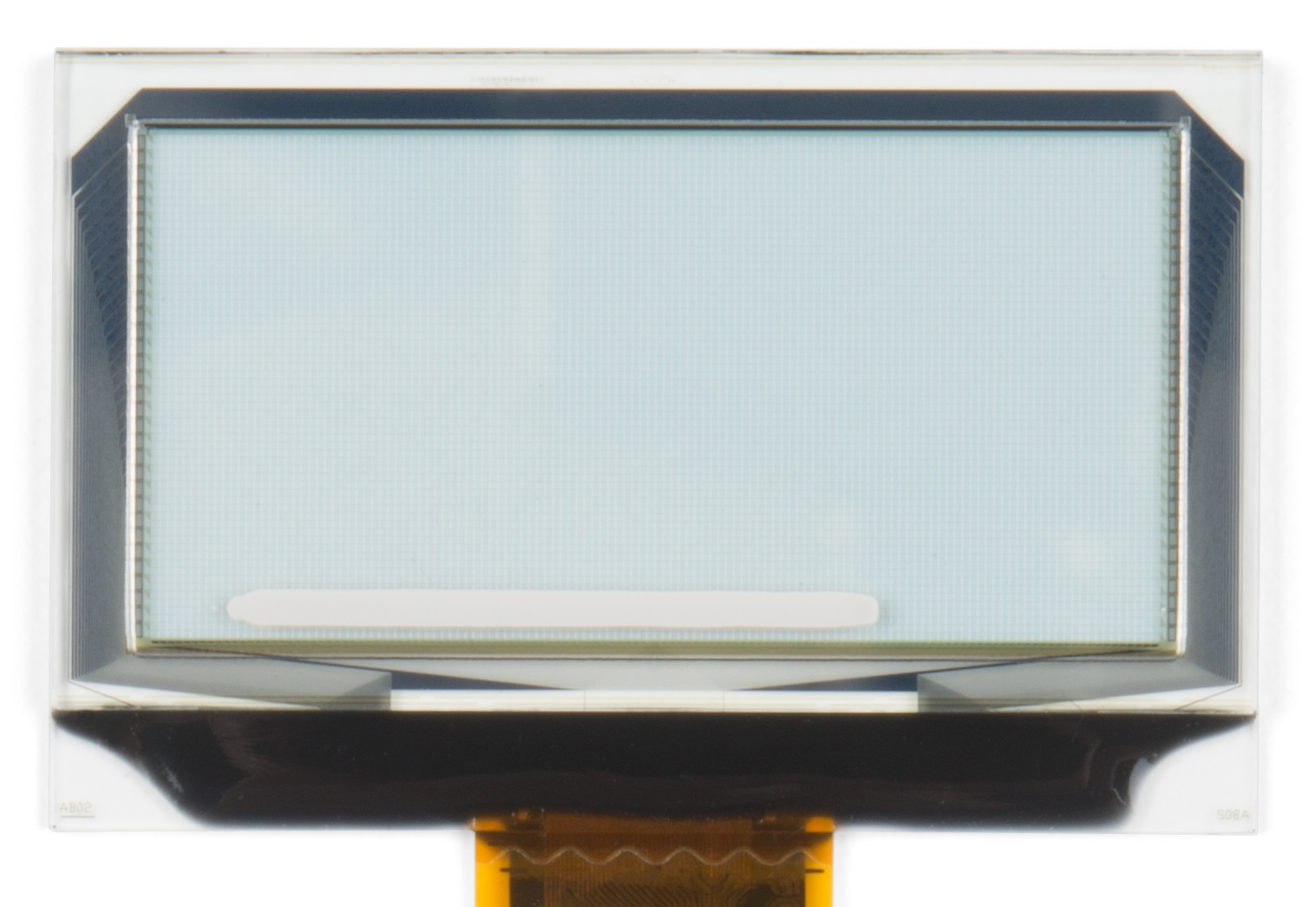 |
| Graphical Display |
Qwiic Connectors
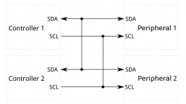
There are two Qwiic connectors on the board such that you can daisy-chain the boards should you choose to do so. If you're unfamiliar with our Qwiic Connect System, head on over to our Qwiic page to see the advantages!
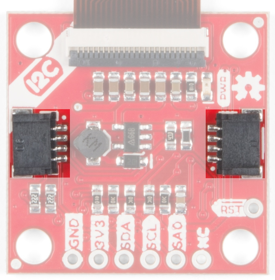 |
| Qwiic Connectors |
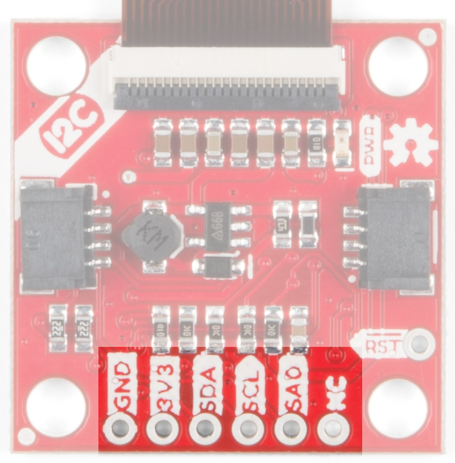
GPIO Pins
When you look at the GPIO pins, you'll notice that the labels are different from one side to the other. One side is labeled for I2C, the other side is labeled for SPI.
 |
 |
| I2C Labels | SPI Labels |
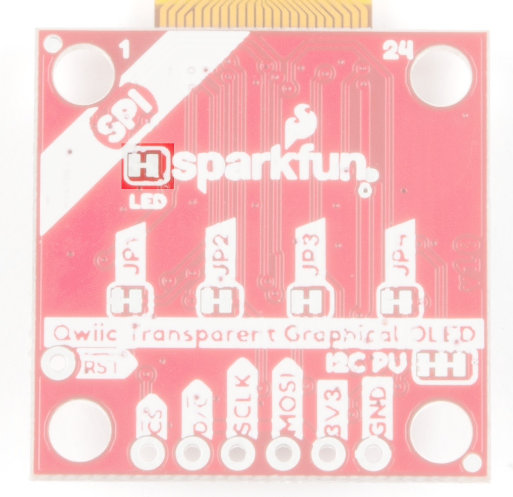
Power LED
This bad boy will light up when the board is powered up correctly.
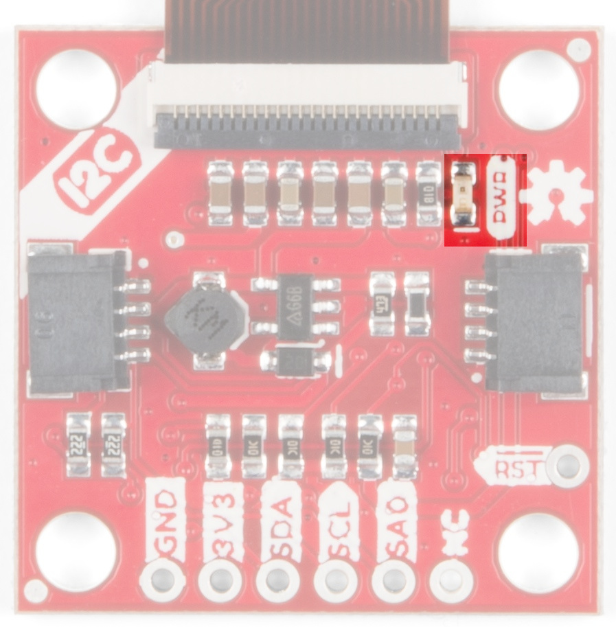 |
| Power LED |
You can disable the power LED by cutting the LED jumpers on the back of the board.
 |
| Power LED Jumpers |
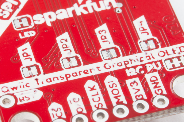
JPX Jumpers
The JPX jumpers are used to either change the I2C address or configure the board to use SPI communications. The other two jumpers allow you to disconnect the power LED and to disconnect the I2C pull-up resistors when chaining several Qwiic devices.
| Jumper | Function |
|---|---|
| JP1 | Holds the Chip Select line low when closed. Close for I2C, open for SPI |
| JP2 | Selects the address in I2C mode. Closed for 0x30 by default and open for 0x31. Open for SPI mode to release the D/C pin |
| JP3 | Used to select I2C or SPI mode. Close for I2C, open for SPI |
| JP4 | This jumper should be closed for I2C and open for SPI. This connection allows SDA to be bi-directional |
 |
| JPX Jumper |
I2C Pull-Up Jumper
I2C devices contain open drains so we include resistors on our boards to allow these devices to pull pins high. This becomes a problem if you have a large number of I2C devices chained together. If you plan to daisy chain more than a few Qwiic boards together, you'll need to cut this I2C pull-up jumper.
 |
| I2C PU Jumper |
Hardware Hookup
Now that you know what's available on your breakout board we can check out the options for connecting it to the brains of your project. There are two options to use - either I2C or SPI - and they each have their own advantages and drawbacks. Read on to choose the best option for your setup.
Warning
Reminder! This breakout can only handle up to 3.3V on the pins, so make sure to do some level shifting if you're using a 5V microcontroller.
I2C (Qwiic)
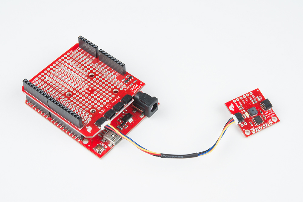
The easiest way to start using the Transparent Graphical OLED is to use a Qwiic Cable along with a Qwiic compatible microcontroller (such as the ESP32 Thing Plus). You can also use the Qwiic Breadboard Cable to attach any I2C capable microcontroller, or take the scenic route and solder in all the I2C wires to the plated-through connections on the board.
|
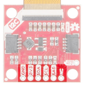 |
| Top View | I2C Pinout/i> |
So why use I2C? It's easy to connect with the Qwiic system, and you can put up to two of the Transparent Graphical Breakouts on the same bus without using any more microcontroller pins. That simplicity comes at a cost to performance though. The maximum clock speed of the I2C bus is 400 kHz, and there is additional overhead in data transmission to indicate which bytes are data and which are commands. This means that the I2C connection is best for showing static images.
| Breakout Pin | Microcontroller Pin Requirements |
|---|---|
| GND | Ground pin. Connect these so the two devices agree on voltages |
| 3V3 | 3.3V supply pin, capable of up to 400 mA output |
| SDA | SDA - the bi-directional data line of your chosen I2C port |
| SCL | SCL - the clock line of your chosen I2C port |
| SA0 | Optional : change the I2C address of the breakout. Make sure to cut JP2 |
| RST | Optional : reset the breakout to a known state by pulsing this low |
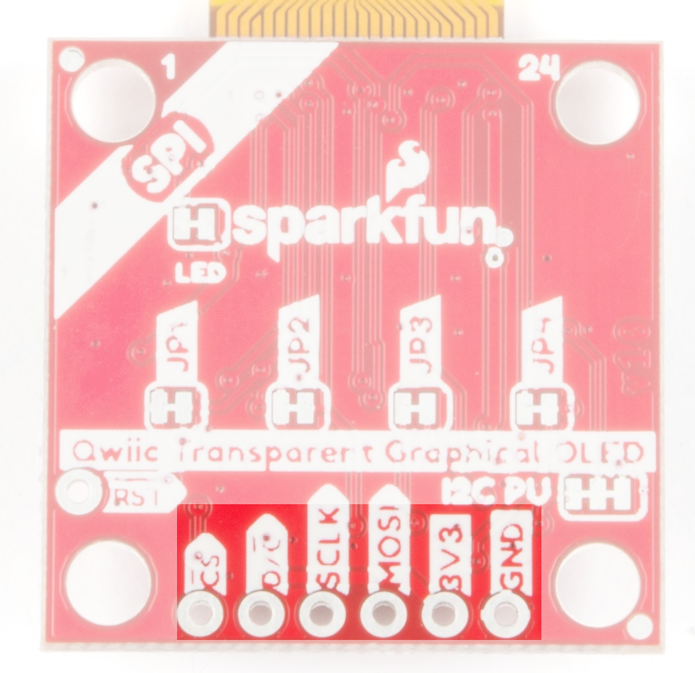
SPI
SPI solves the I2C speed problems. With SPI there is a control signal that indicates data or command and the maximum clock speed is 10 MHz -- giving SPI 50x more speed! However, it doesn't have the same conveniences of the polarized Qwiic connector and low pin usage. You'll need to solder to the pins.
|
| SPI Pinout |
You can use SPI to connect as many breakouts as you want. For N displays you will need to use at least N + 3 data pins. That's because the MOSI, SCLK, and D/C pins can be shared between displays but each breakout needs its own dedicated Chip Select (CS) pin.
| Breakout Pin | Microcontroller Pin Requirements |
|---|---|
| CS | A GPIO pin, set low when talking to the breakout |
| D/C | A GPIO pin, indicates if bytes are data or commands |
| SCLK | The clock output of your chosen SPI port |
| MOSI | The data output of your chosen SPI port |
| 3V3 | 3.3V supply pin, capable of up to 400 mA output |
| GND | Ground pin. Connect these so the two devices agree on voltages |
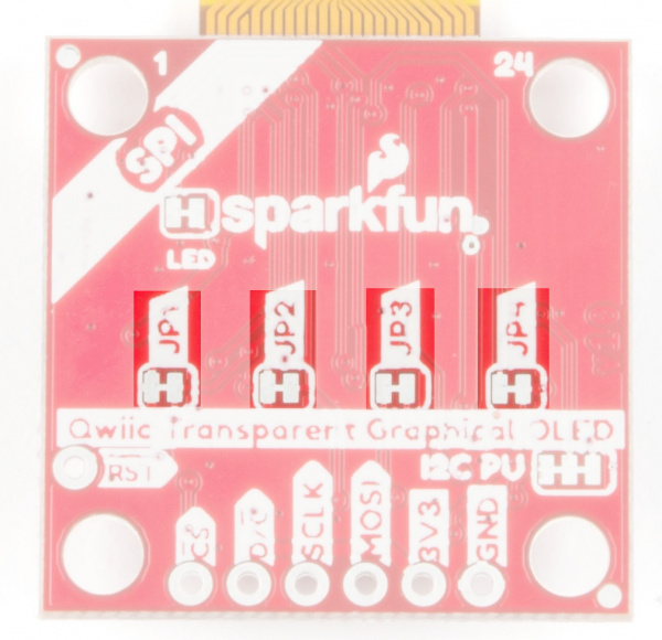
Warning
Make sure to cut jumpers JP1, JP2, JP3, and JP4 when using SPI mode!
 |
| Cut Jumpers for SPI Mode |
Software
The Transparent OLED Breakout (Qwiic) uses the SparkFun QWIIC OLED Arduino Library. The SparkFun Qwiic OLED library Getting Started guide has library setup instructions and usage examples. Additionally, the full library API documentation is available in the SparkFun Qwiic OLED Library API Reference guide.
Resources
For more information on the Transparent Graphical OLED Breakout, check out some of the links here: